B748 Powerplant System
1/37
There's no tags or description
Looks like no tags are added yet.
Name | Mastery | Learn | Test | Matching | Spaced | Call with Kai |
|---|
No analytics yet
Send a link to your students to track their progress
38 Terms
What protection is available to prevent idle thrust asymmetry condition on the ground? FCOM 1 - 70.20.5
Thrust control malfunction protection
The EEC provides protection against thrust control malfunctions that can result in an idle thrust asymmetry condition on the ground. The EEC commands shutdown of the affected engine when:
• airplane is on the ground,
• thrust lever is approximately at idle, and
• engine is above command N1 speed and not decelerating normally
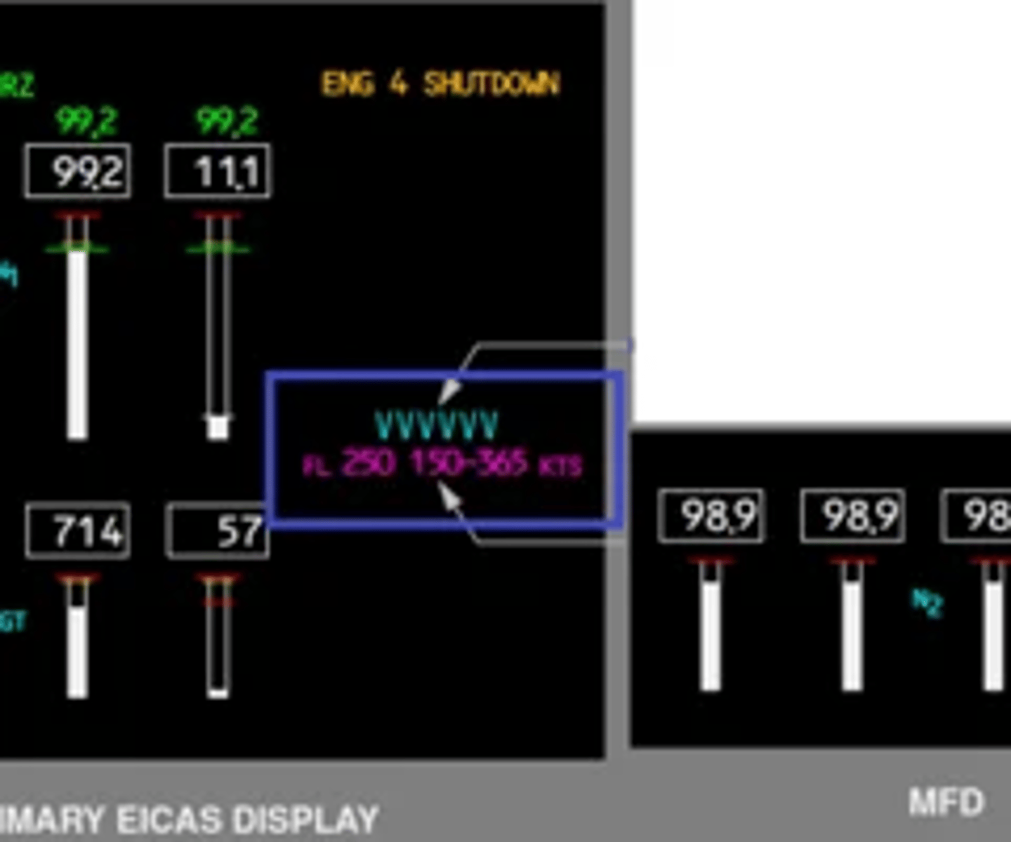
What will be the indication if the starter is required for an in flight start? 70.20.6
An in-flight start envelope displays on primary EICAS and the secondary engine indications display when a Fuel Control switch is moved to CUTOFF in flight. The in-flight start envelope displays the airspeed range to ensure an in-flight start at the current flight level. If the current flight level is greater than the maximum start altitude, the maximum start altitude and respective airspeed range display. X-BLD displays next to the N2 indication if crossbleed air is necessary for start.
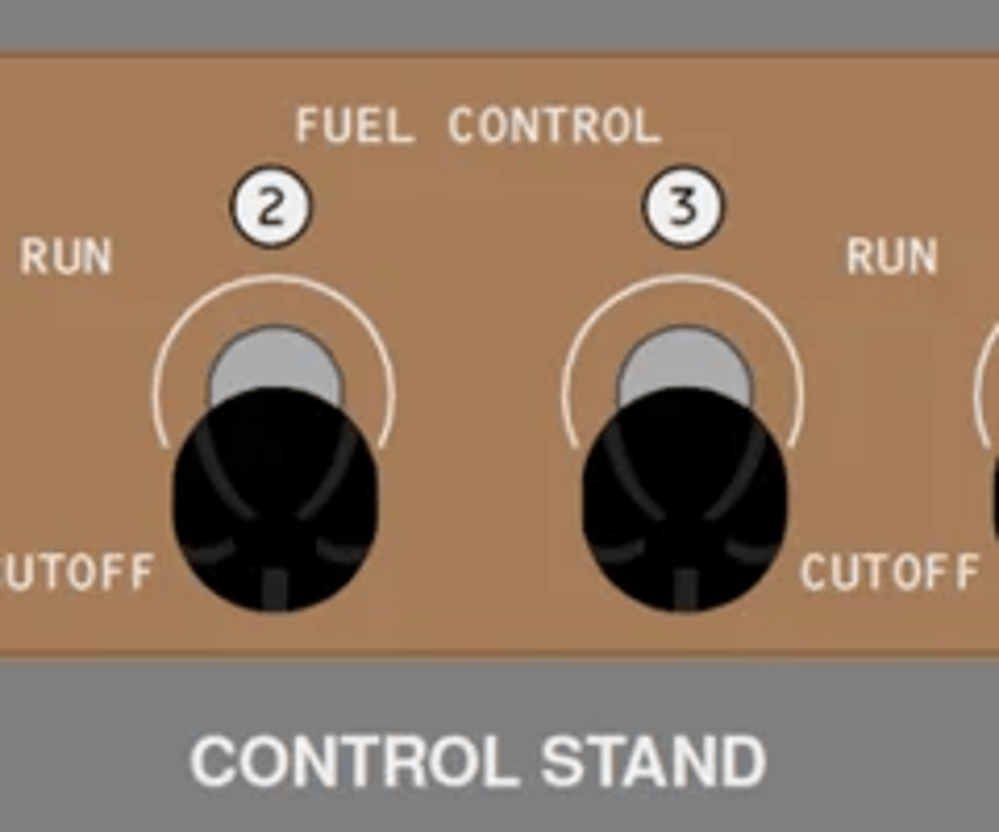
Which valve opens when fuel control switch is selected to run during a start? FCOM 1 - 70.10.2
RUN—
• opens spar fuel valve
• arms the engine fuel valve (the EEC opens the valve when required)
• arms the igniter(s) (the EEC turns the igniters on when required)
When does start valve close during engine start? FCOM 1 - 70.20.6
Starter cutout occurs at approximately 54% N2 RPM.
When does the engine motor for longer duration before starting? 70.20.6
When an engine has been shut down for 30 to 360 minutes and the EGT is greater than 30 degrees C, motoring continues an additional 40 seconds when N2 reaches 20%. The start then continues normally.
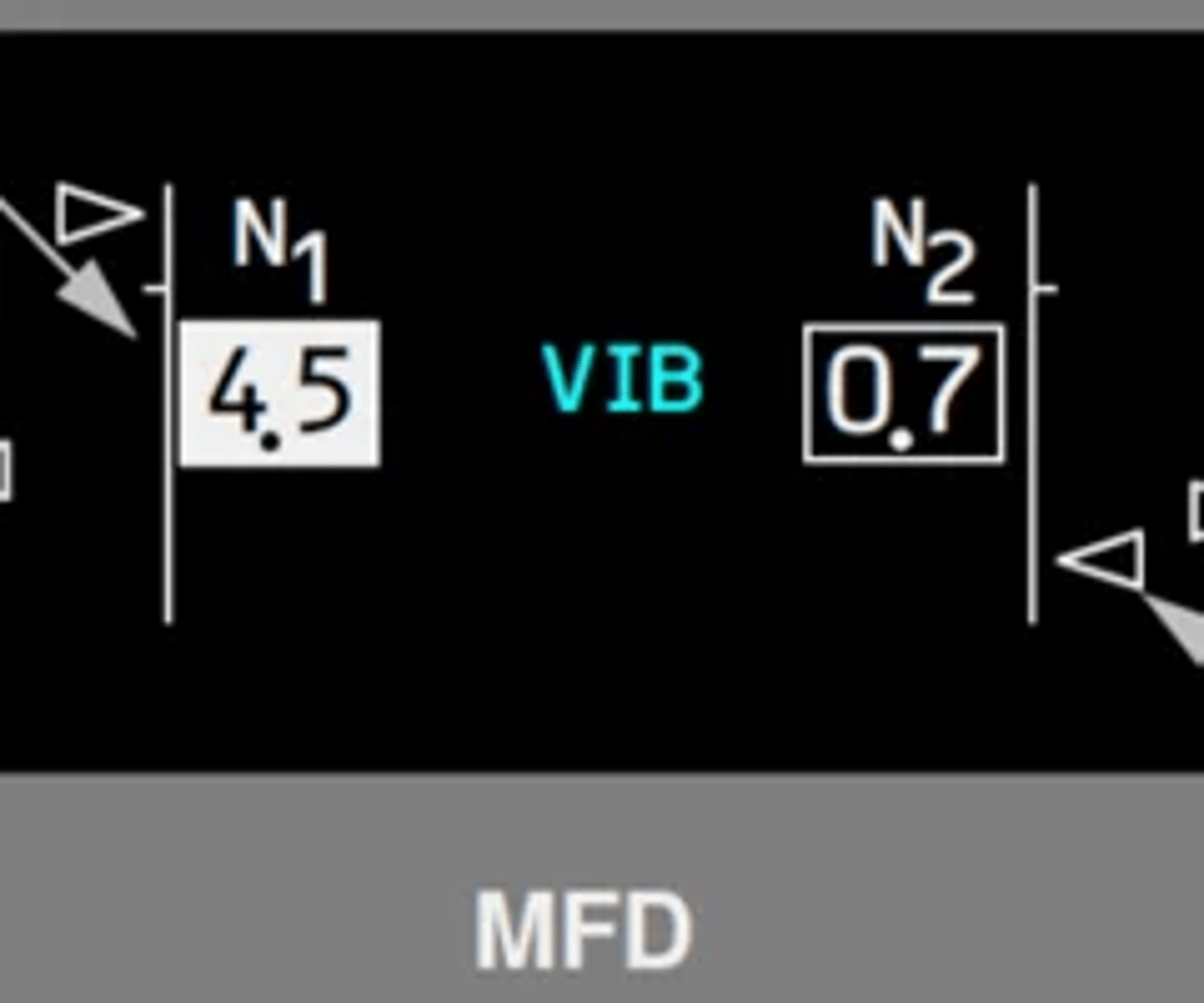
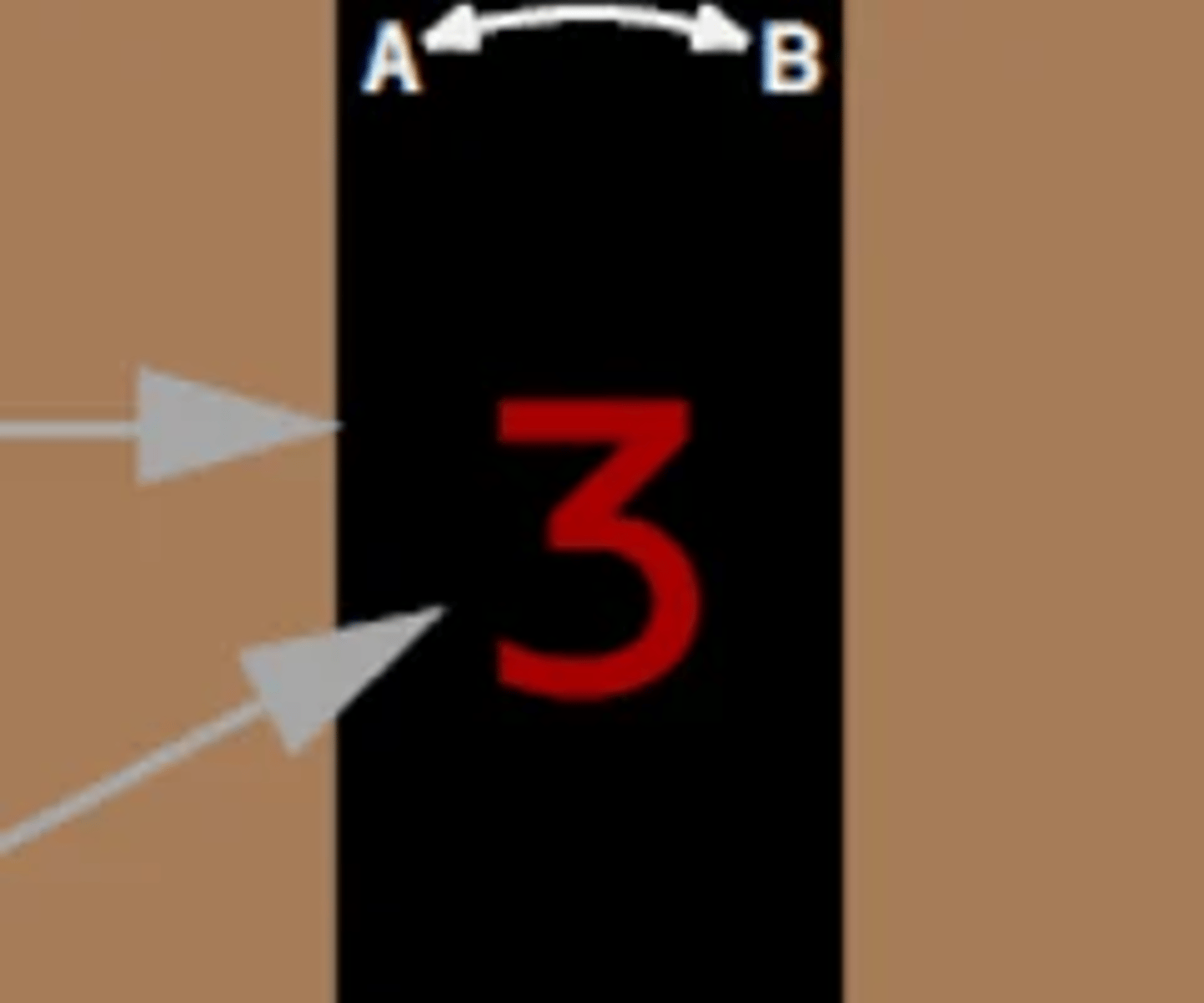
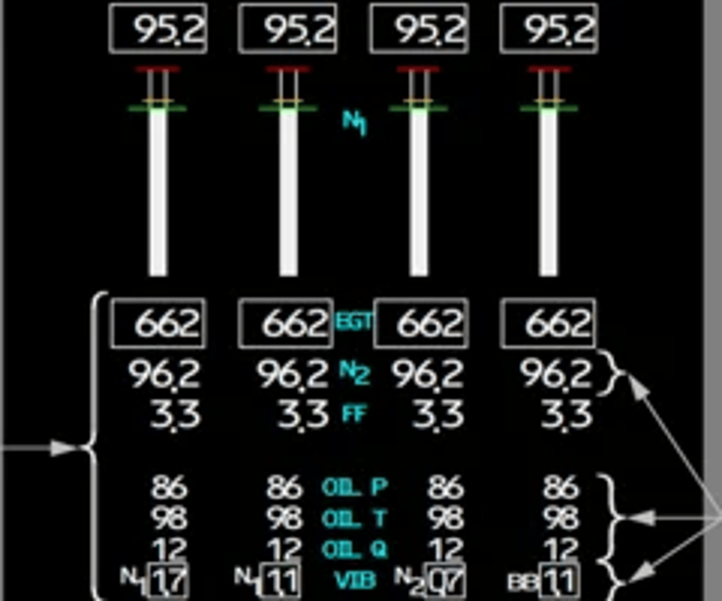
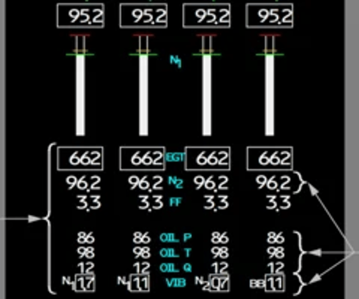
What are the indications for engine vibration and where is it displayed? FCOM 1 - 70.10.17
Identifies the vibration source being displayed.
Displayed (white)— vibration source with the highest vibration:
• N1—N1 fan/turbine vibration
• N2—N2 rotor vibration
If vibration source BB (broad band vibration) displayed, source is unknown and average vibration displayed.
How many igniters are normally used FCOM 1 - 70.20.7/8
- 1st engine start: one igniter
- 2nd engine start attempt: two igniters with EGT no rise
- auto-relight: always two igniters
- Dual igniters are always used for in-flight starts.
When is auto-relight protection provided and where is the indication displayed? FCOM 1 - 70.20.8
An auto-relight capability is provided for flame out protection.
A flame out is detected when a rapid decrease in N2 occurs, or N2 is less than idle RPM.
Which valves close when the fire switch is pulled? FCOM 1 - 26.10.1
• closes the respective engine and spar fuel valves
• closes the respective engine bleed air valve
• trips off the respective engine generator
• shuts off hydraulic fluid to the respective engine driven hydraulic pump
• depressurizes the respective engine-driven hydraulic pump
• arms both respective engine fire extinguishers
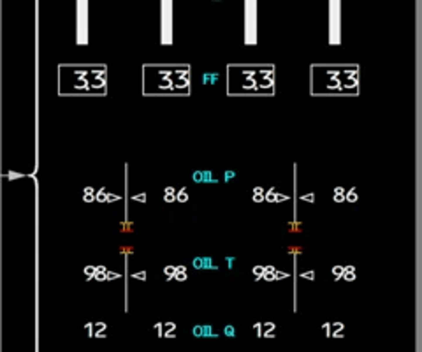
How is fuel flow indicated and where is the measurement taken from? FCOM 1 - 70.20.10
Fuel flow is measured downstream of the engine fuel valve and displays on the secondary engine display. Fuel flow information is also provided to the FMS.
(kilograms per hour × 1000).

What are the heat exchangers used for engine oil cooling? FCOM 1 - 70.20.12
The oil is cooled by fuel as it flows through the fuel/oil heat and air/oil heat exchangers.
What will cause partial engine display to appear? what are the colors of the abnormal indications? FCOM 1 - 70.20.3
Secondary engine indications display in partial format if a secondary engine parameter exceeds the normal operating range when the secondary engine display
is not selected. The secondary engine exceedance cue displays on primary EICAS when an exceedance occurs.
What is used to operate the thrust reversers? FCOM 1 - 70.20.14
Each engine has a hydraulically actuated fan air thrust reverser. Each thrust reverser is powered by hydraulic pressure from the respective hydraulic system
When can reverse thrust be selected? FCOM 1 - 70.20.14
Reverse thrust is available only on the ground.
What is the protection preventing simultaneous movement of the forward and reverse thrust levers? FCOM 1 - 70.20.14
An interlock mechanism in the Thrust lever assembly prevents simultaneous movement of the Forward and Reverse Thrust levers.
How does pilot reduce vibration caused by wind milling engine after shutdown? FCOM 1 - 70.20.14
In general, air frame vibrations can best be reduced by descending and reducing airspeed. However, if after descending and reducing airspeed, the existing vibration level is unacceptable, and if it is impractical to further reduce airspeed, the vibration level may be reduced to a previous, lower level by a slight increase in airspeed.
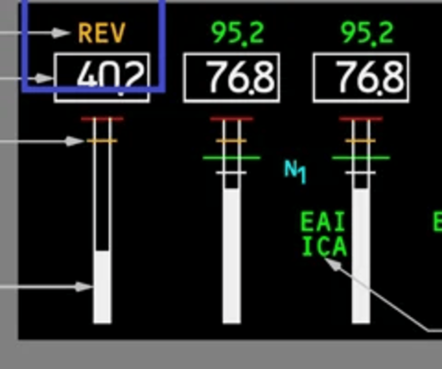
What indications are displayed above N1 display box for the thrust reverser? FCOM 1 - 70.10.8
Displayed REV (amber)—reverser in transit.
Displayed REV (green)—reverser fully deployed.
List the sources and users of center bleed air system
- air conditioning
- pressure
- anit ice
- leading edge flaps
- TAT probe aspiration
- AFT cargo heat
- hydraulic reservoir pressure
- Air driven hydraulic demand pumps
- nitrogen generating system
Which parameters have caution ranges displayed by amber bands? FCOM 1 - 70.20.2
Oil pressure and oil temperature indicators have caution ranges displayed by amber bands.
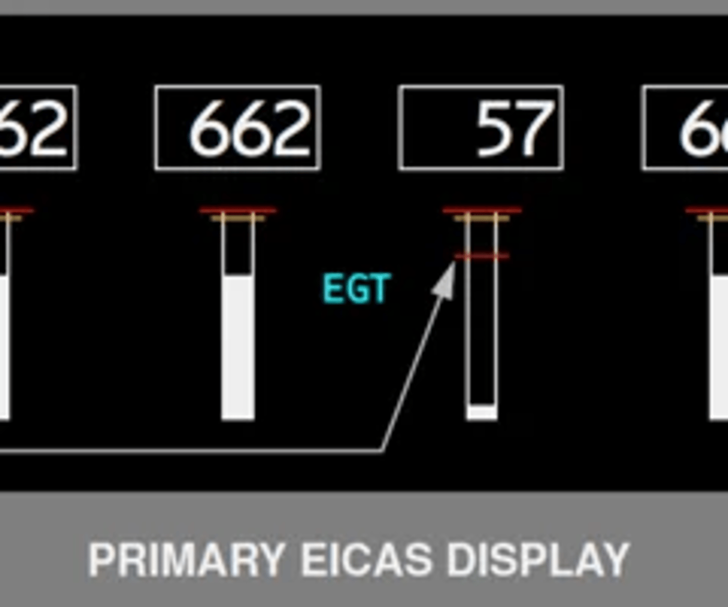
What conditions will inhibit the EGT amber color change? FCOM 1 - 70.20.2
EGT indications are inhibited from changing color to amber during takeoff or go-around for five minutes after the TO/GA switch is pushed, even though EGT reaches the continuous limit. The amber color change is inhibited for ten minutes if one engine fails or is shutdown.
What are the different EGT red line indications? FCOM 1 - 70.20.2
The EGT indicator has a takeoff limit displayed by a red line. The indication changes color to red if EGT reaches the takeoff limit.
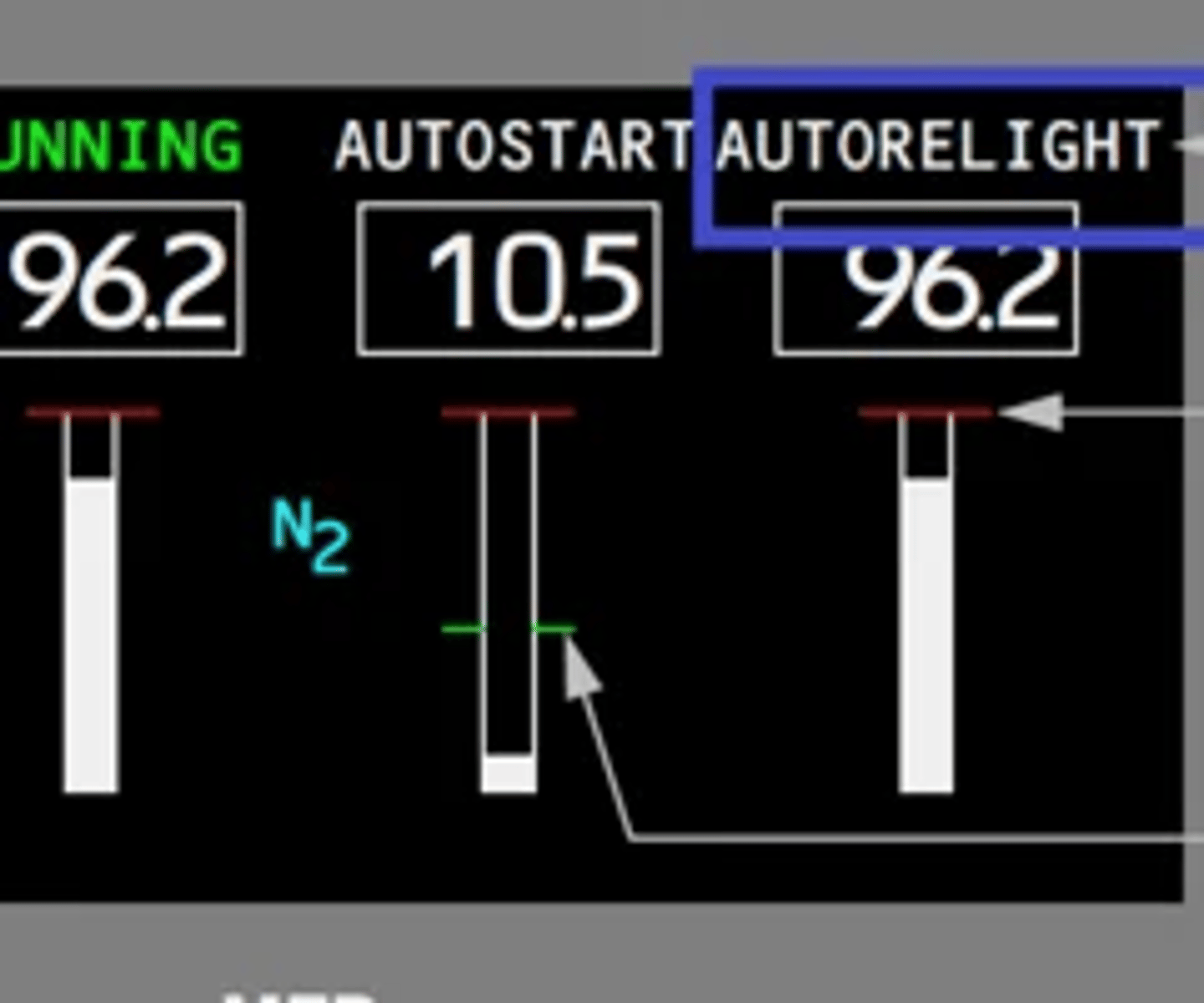
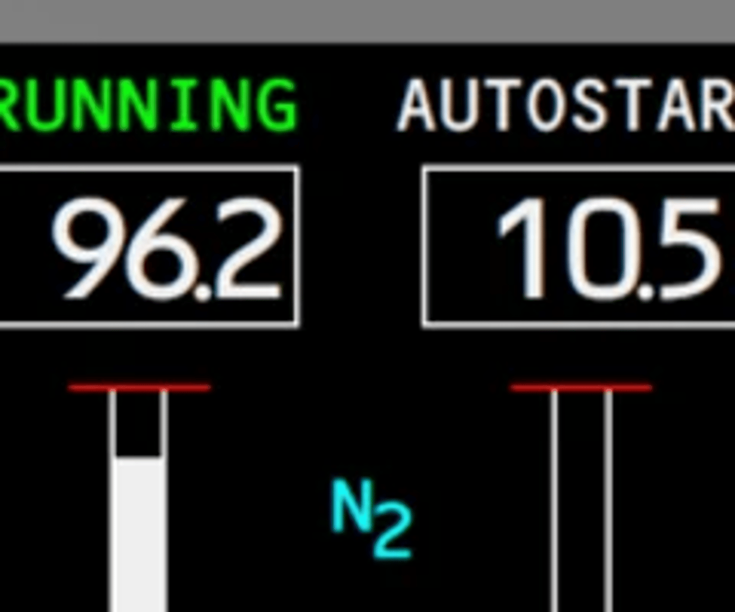
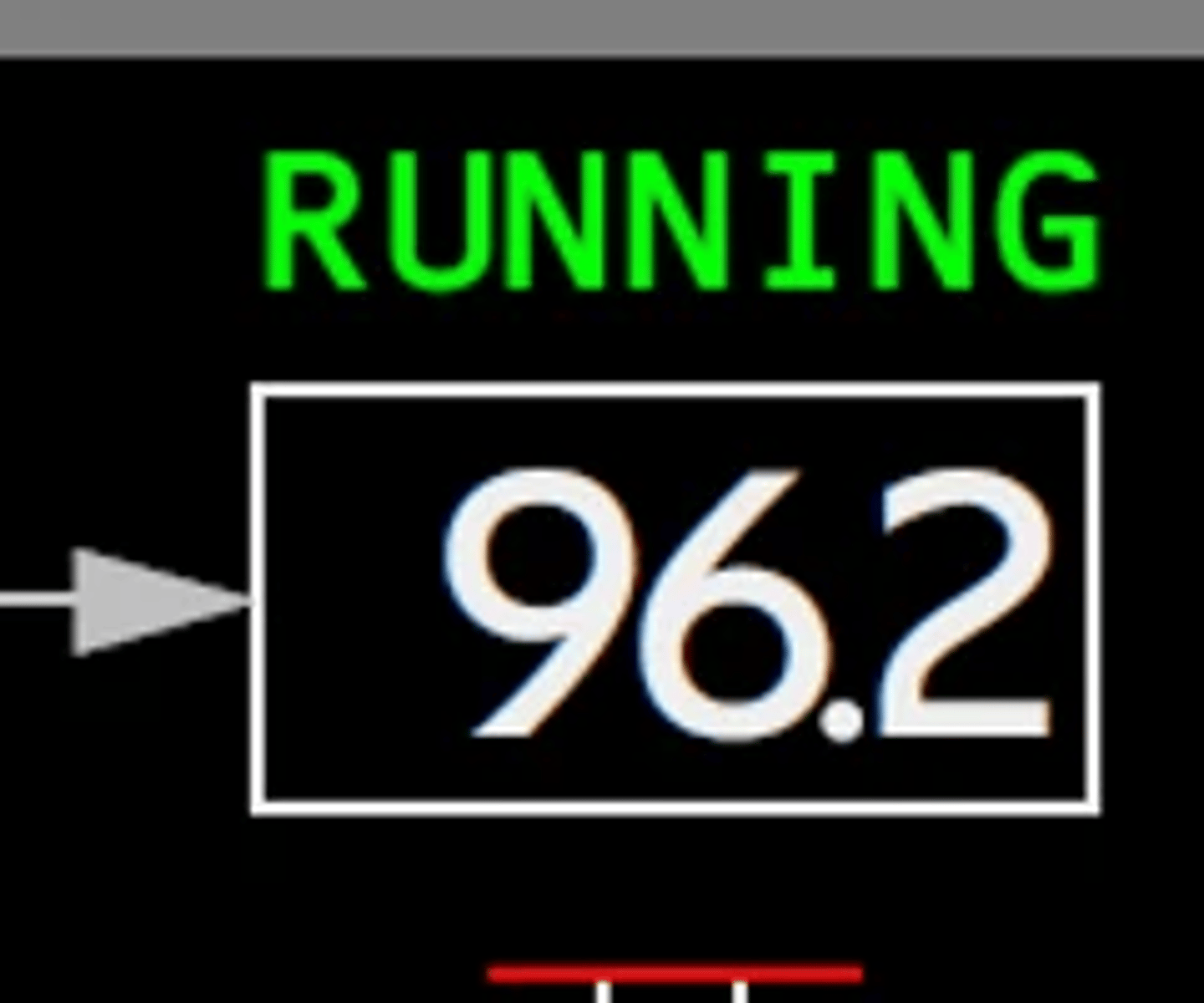
What indications are displayed above N2 display box & what they indicate? FCOM 1 - 70.10.13
RUNNING, displayed (green)—engine at or above idle after start, blanks 30 seconds after achieving idle RPM
AUTOSTART, displayed (white)—engine in start mode
AUTOSTART, displayed ground start—engine START switch pulled, fuel control in RUN
AUTOSTART, displayed in flight—engine below idle, after Fuel Control switch moved from CUTOFF to RUN
AUTORELIGHT, displayed (white)—engine below idle, Fuel Control switch in RUN and not cycled to CUTOFF
How is engine start completion indicated? FCOM 1 - 70.10.13
Running in Green
When will the full page secondary engine indications show on the lower display unit? FCOM 1 - 70.20.1
The secondary engine indications display when:
• the displays initially receive electrical power
• selected using the Engine (ENG) display switch on the Display Select panel
• a Fuel Control switch is moved to CUTOFF in flight
Will there be indication change if EGT reaches maximum continuous limit? FCOM 1 - 70.20.2
Displayed (white)—normal operating range.
Displayed (amber)—continuous limit reached.
Displayed (red)—start or takeoff limit reached.
When will an engine parameter digital indicator box turn red? can it be cancelled? FCOM 1 - 70.20.2
Displayed (red)—start or takeoff limit reached.
box enclosing the digital indicator remains red as a reminder of the exceedance. The red box color can be selectively canceled to white or recalled to red by pushing the cancel recall (CANC RCL) switch on the Display Select panel.
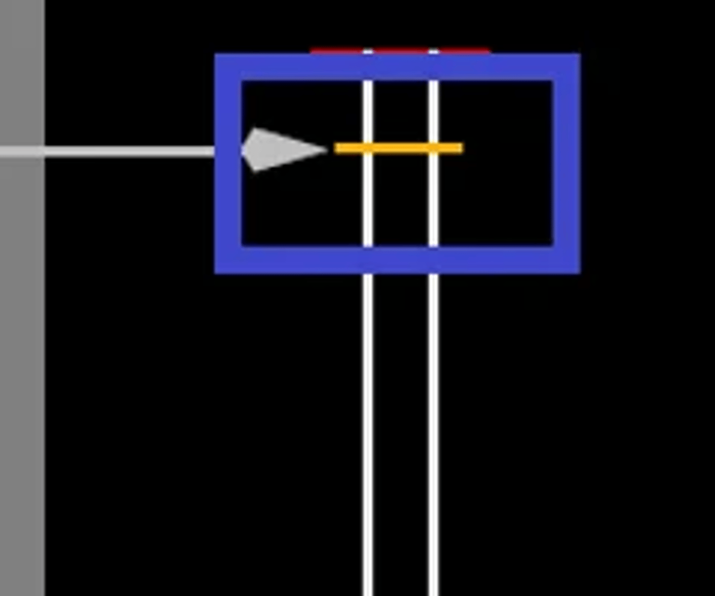
What does the amber line on the N1 indicator represent? FCOM 1 - 70.10.8
maximum N1
When will partial display of the secondary engine parameters be presented? how can the display return to normal? FCOM 1 - 70.20.3
- when a secondary engine parameter exceeds the normal operating range when secondary engine display is not selected
- will remain displayed until the exceeding engine parameter returns to normal
What is the controlling parameter of the EEC in normal mode and alternate mode? FCOM 1 - 70.20.3
In both normal and alternate modes, the EEC uses N1 RPM as the controlling parameter for setting thrust.
When is ice crystal icing protection active and how does the engine operate? FCOM 1 - 70.20.4
- When ice crystal icing conditions are detected for an engine, variable bleed valves open to extract ice crystals out into the fan duct. Every 35 seconds for 15 minutes, the variable bleed valves are closed and re-opened. So long as ice crystal icing conditions are detected, the 15 minute cycle is repeated.
- when ice crystal icing conditions are detected higher than 30,000 feet
- stops during descent <28,000 feet
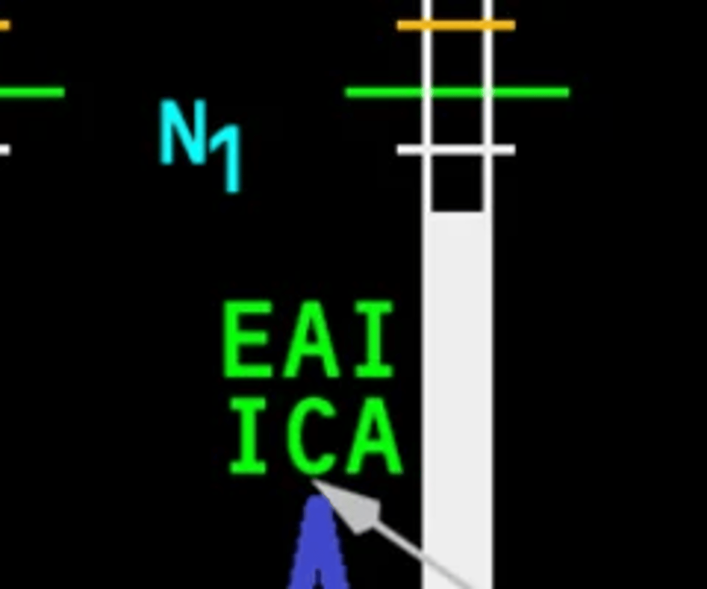
What is the flight deck indication for ice crystal icing operation? FCOM 1 - 70.20.4
When the ice crystal anti-icing system on an engine is operating, ICA is displayed on primary EICAS for that engine.
How will the EEC cope with changes in engine bleed load during climb? FCOM 1 - 70.20.4
When the engine is stabilized, EEC keeps thrust constant independent of outside air temperature and pressure. The EEC adjusts thrust for changes in engine and wing anti-ice and airplane pressurization bleed requirements. This allows a fixed Thrust lever position throughout a climb.
How is engine thrust affected as EEC automatically changes from normal to alternate? FCOM 1 - 70.20.5
Alternate mode does not provide thrust limiting at maximum N1. Maximum N1 is reached at a Thrust lever position less than full forward. Thrust levers must be adjusted to maintain desired thrust as environmental conditions and bleed requirements change.
Thrust does not change when EEC transfers control from normal mode to alternate mode
How is engine thrust affected as the EEC mode is manually changed from normal to alternate? FCOM 1 - 70.20.5
Thrust increases when alternate mode is selected
manually. When thrust is greater than idle, the Thrust lever should be moved aft prior to manually selecting alternate mode so thrust does not exceed maximum N1.
Which EEC mode support auto-throttle operations? FCOM 1 - 70.20.5
- normal and alternate
- autothrottle can be re activated once all EEC are manually transferred to alternate mode
How does EEC prevent rotor overspeed & what is the maximum speed? FCOM 1 - 70.20.5
- Overspeed Protection: At thrust settings above idle, the EEC monitors N1 and N2 RPM to prevent rotor
overspeed. If a rotor approaches overspeed, the EEC commands the fuel metering unit to reduce fuel flow to keep rotor speed from exceeding the operating limit even though the Thrust lever is commanding more thrust.
- N1 106.7%max
- N2 B 118% max P 117.5%max (L.15.2)
What are the conditions that will cause the EEC to provide approach idle? FCOM 1 - 70.20.5
Approach idle is selected in flight when:
• engine anti-ice is ON, or
• landing gear is down, or
• flaps 20 is selected, or
• flaps are in landing position
How long is engine approach idle available after touchdown? FCOM 1 - 70.20.5
Approach idle is maintained until five seconds after touchdown, when minimum idle is selected.