SYSC3313 - Chapter 2 More UML Diagrams (Besides State Diagrams)
1/22
There's no tags or description
Looks like no tags are added yet.
Name | Mastery | Learn | Test | Matching | Spaced | Call with Kai |
|---|
No analytics yet
Send a link to your students to track their progress
23 Terms
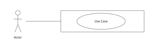
Use case diagrams
Define a sequence of interactions between actors and the system.
Connect actors with use cases they participate in.
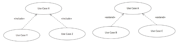
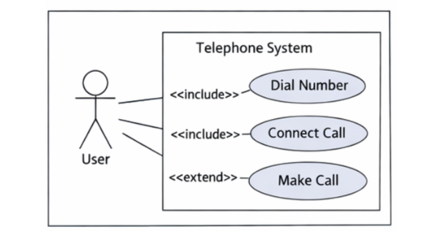
Include and Extend Relationship in UML Use Case Diagrams
Include: a use case always includes another use case as part of its behavior
Extend: Optional extension of a use case under certain conditions
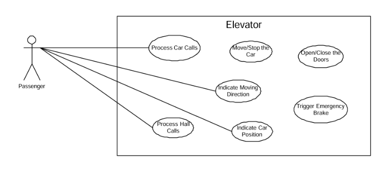
Elevator System Use Case Diagram Example
Telephone system use case diagram example
UML class diagrams
A structural diagrams that shows system classes, their attributes and operations, and relationships between them.
Class = building block
component = collection of building blocks
Classes in UML class diagrams
Describes general structure of as system including the types of components, their attributes, and operations (Elevator, door, button)
Objects in UML diagrams
Used to represent a specific instance of a class, showing how it behaves or interacts during system execution (door1 opening or elevator1 moving)
Used by sequence and communication diagrams to model runtime interactions
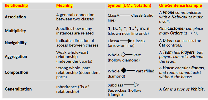
Relationships in UML class diagrams
association: general connection
multiplicity: specifies number of instances that are related
navigability: indicates direction of access between classes
aggregation: weak whole-part relationship, where the part can exist on its own
composition: strong whole-part relationship, where the part cannot exist on its own
generalization: inheritance
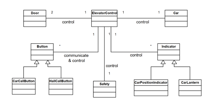
Class diagram example of simle elevator system
UML Interaction Diagrams
sequence diagrams
communication diagrams
Indicate how objects interact
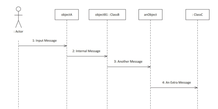
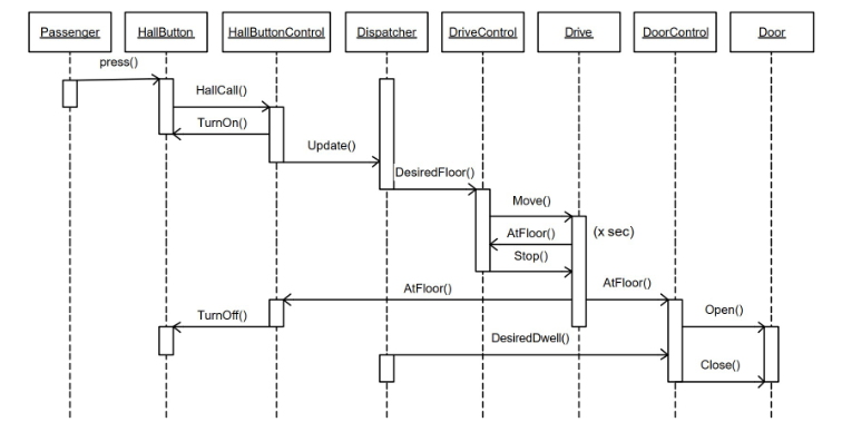
UML sequence diagram
Shows how objects interact over time by exhcaning messages in a specific order.
Elevator Hall Call Use Case Example
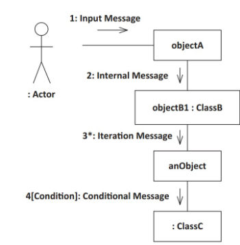
UML Communication Diagrams
Illustrates how objects interact by showing ojbects as boxes connected by links, along with the messages exchanged between them.
Compared to sequence diagrams, it emphasizes the sturcutal relationships between objects while still representing the order of interactions.
lifeline: object that participates in an interaction
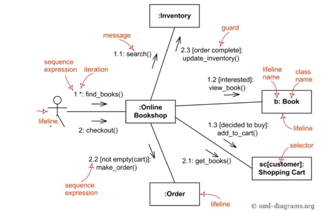
Communication diagram online book shop example
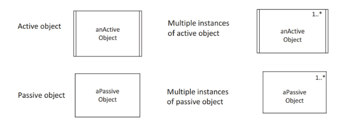
Active vs Passive Objects in UML Sequence and Communication diagrams
Objects that have their own control logic are called active objects.
Some objects don’t have their own thread or process. They only exists when a process or thread invokes them. These are passive objects.
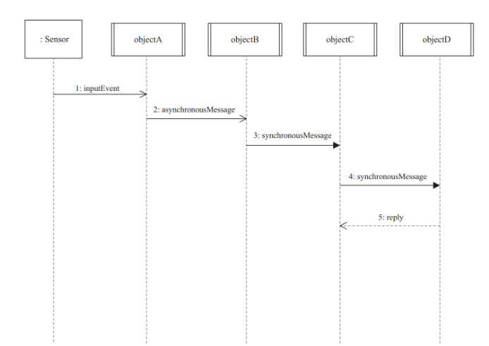
Example of concurrent sequence diagram
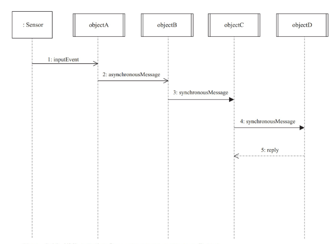
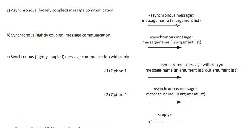
Asynchronous vs Synchrnous Messages in Concurrent Sequence and Communication Diagrams
asynchronous: shown with open arrowhead, allow sender to continue without waiting for reply or completion.
synchronous: shown with filled arrowhead, required sender to wait for completion, with or without a reply.
Concurrent Sequence Diagram with different messages example
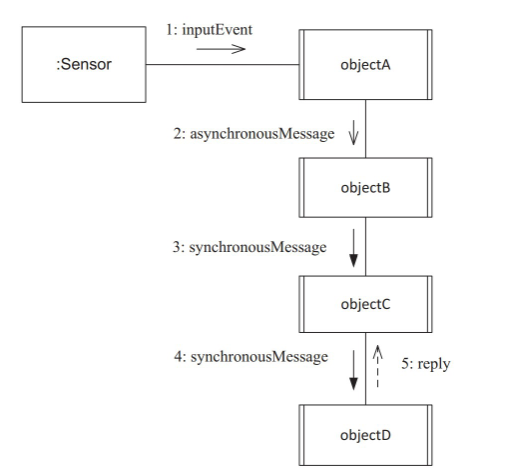
Concurrent communication diagram with different messages
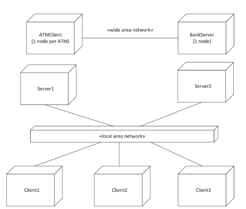
Deployment diagrams
Show physical configuration of a system, inlcuding nodes (usually computers) and teh connections between them (like LAN or WAN).
Nodes are represented as cubes, and connections as labeled links indicating the type of network. You can also show the objects deployed on each node and support multiple node instances.
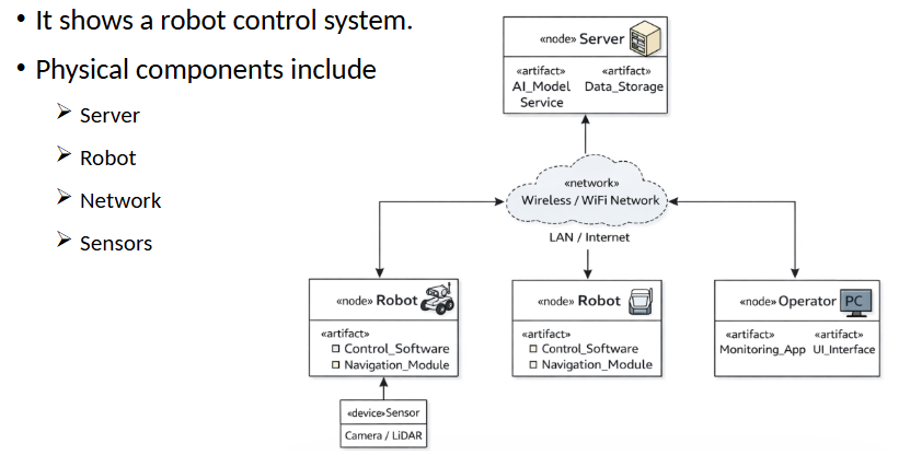
Robot Control System Deployment Diagram Example
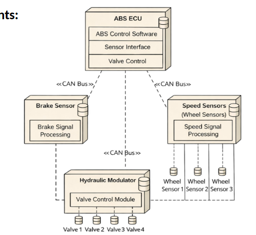
ABS system deployment diagram example
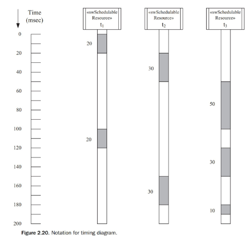
Timing diagram
Time-annotated sequence diagram that shows the execution of concurrent tasks over time.
Time is marked explicitly along the veritcal axis. Lifelines represent tasks and shaded segments indicate when the task is actively executing and for how long.