Magnetic Fields and Forces
1/21
There's no tags or description
Looks like no tags are added yet.
Name | Mastery | Learn | Test | Matching | Spaced | Call with Kai |
|---|
No analytics yet
Send a link to your students to track their progress
22 Terms
Magnetic flux density
Magnetic flux density (B) measures the strength and direction of a magnetic field, defined as the amount of magnetic flux (ϕ) passing through a unit area (A) perpendicular to the field.
B = ϕ/A
B = magnetic flux density (measure in T, Tesla)
where ϕ = magnetic flux (measured in webers, Wb)
and A = area (measured in m2)
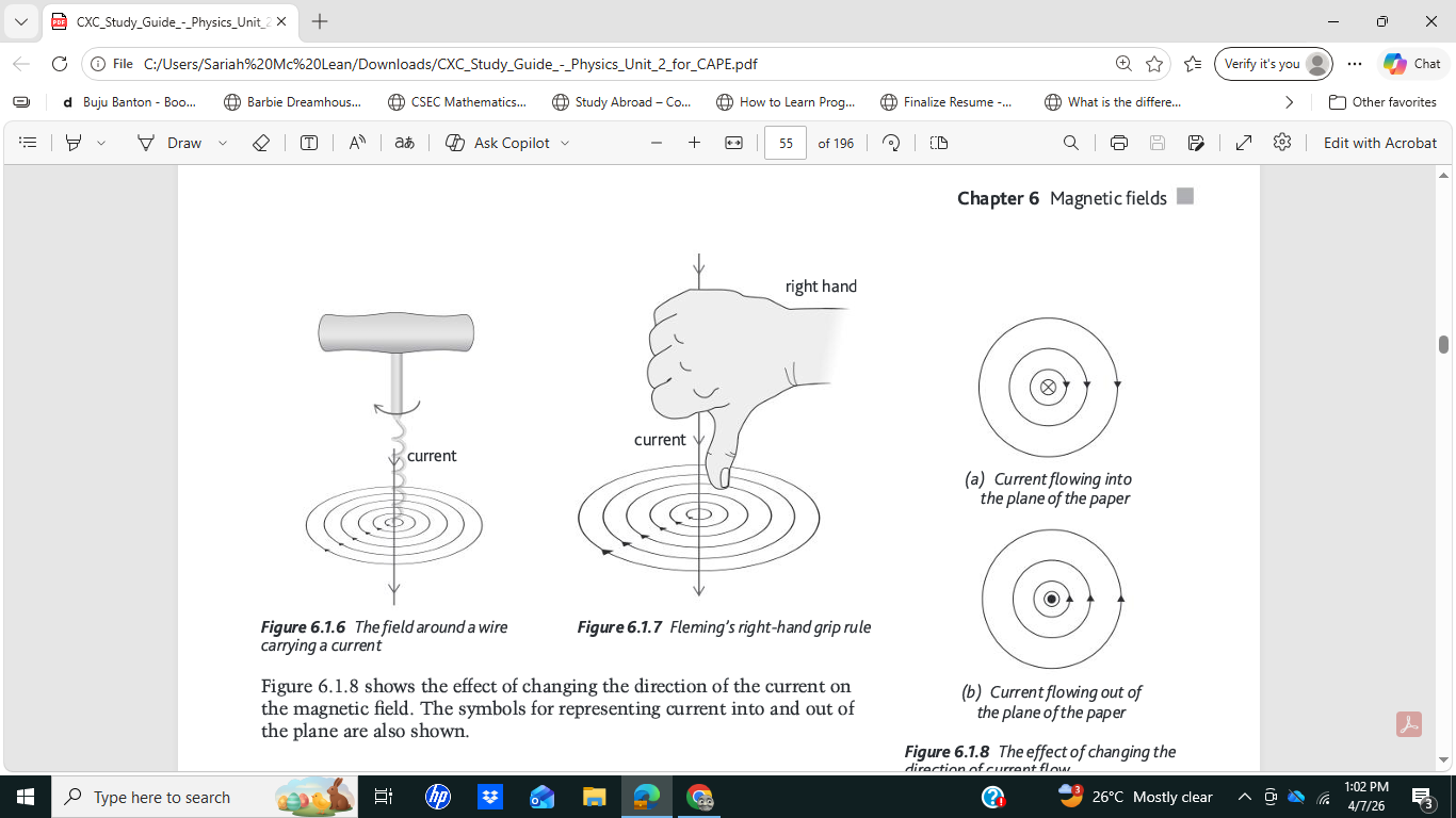
Magnetic flux patterns due to a long straight wire
B = μ₀I / 2πr
where μ₀ = permeability of free space /Hm-1
I = current/A
r = perperdicular distance from conductor/m
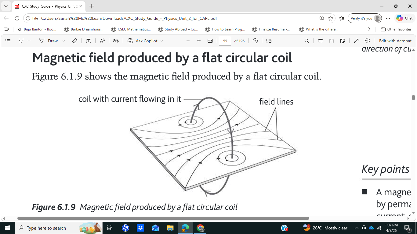
Magnetic field produced by a fl at circular coil
B = μ₀NI / 2r
Where N = number of turns
μ₀ = permeability of free space /Hm-1
I = current/A
r = perperdicular distance from conductor/m
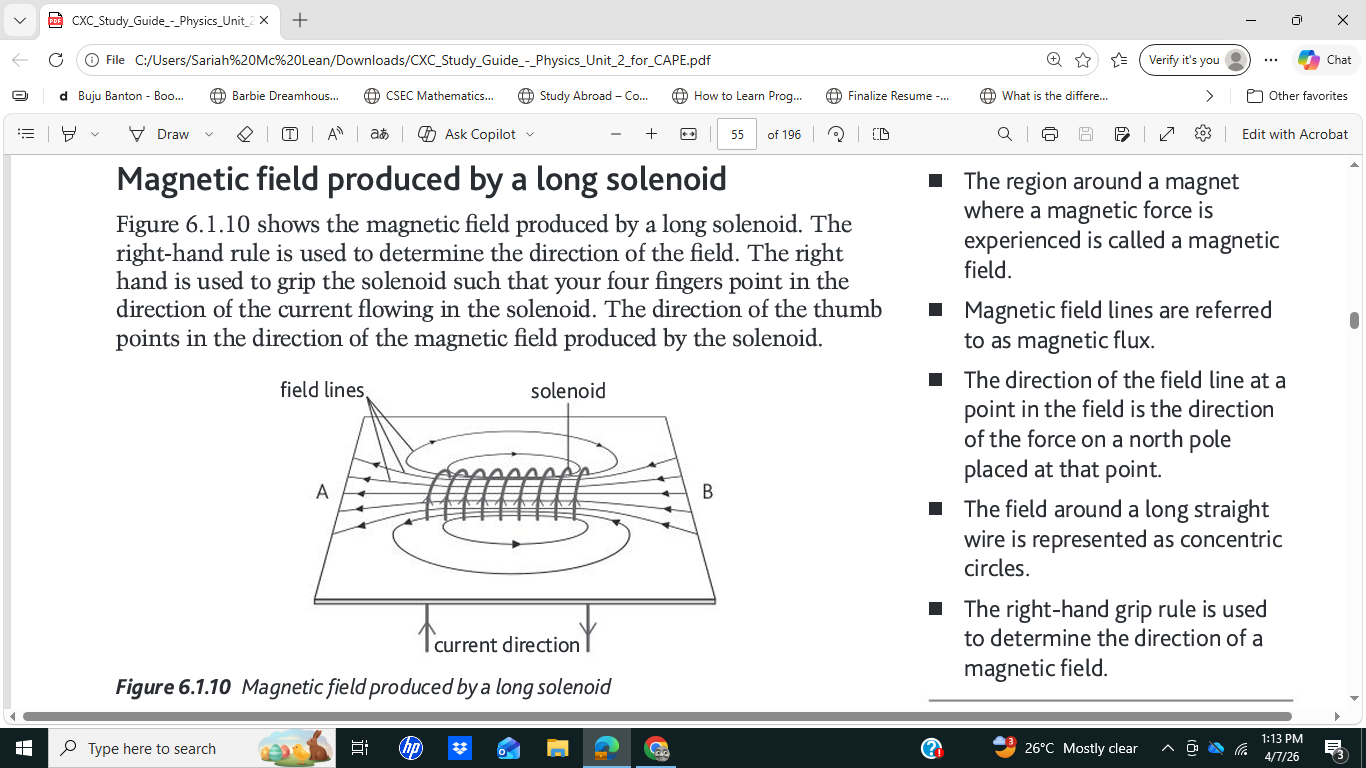
Magnetic field produced by a long solenoid
B = μ₀nI
where n = number of turns per unit length N/L
μ₀ = permeability of free space /Hm-1
I = current/A
r = perperdicular distance from conductor/m
Force acting on a charge moving in a magnetic field
F = BQv
F – force on charge/N
B – magnetic flux density/T
Q – charge/C
v – speed/ms^−1
A particle with charge Q, travelling with a speed v at an angle of θ to the magnetic field
F = BQv sinθ
F – force on charge/N
B – magnetic flux density/T
Q – charge/C
v – speed/ms−1
θ – angle between v and B
Hall effect
A potential difference is set up transversely across a current-carrying conductor when a perpendicular magnetic field is applied.
What is a Hall Probe and how does it work?
Purpose: Measures magnetic flux density (B).
How it works:
Uses semiconductor slice (charge carriers have high drift velocity → larger Hall voltage).
Place semiconductor perpendicular to magnetic field.
Pass small constant current I through it.
Measure Hall voltage V_H.
Formula:
B=VHnet / I
(Manufacturer gives n e t value; device is calibrated in known fields.)
What is a current balance and how does it work?
Purpose: Measures magnetic flux density (B).
How it works:
Wire frame (side AB placed perpendicular to field).
Current through frame creates downward force F on side AB.
Adjust rider mass mg until frame balances horizontally (pointer at zero).
Use principle of moments to find F.
Formula (from moments):
F=mg⋅y / x
Then
B=F / Il
then
F = mgy / xlI
where l = length of AB, I = current, x and y are distances from pivot.
The work done on an electron by the electric field is
w = qV or w = eV (same thing)
Magnetic flux
a measure of the total magnetic field (B) passing through a given surface area (A)
Φ = Magnetic flux measured in webers (Wb)
B = magnetic flux density (Tesla/ T)
A = surface area (m2)
EMF (electromotive force) formula
E = V + Ir or E = I(R + r)
Potential divider
Vo = Vin (R2/ R1 + R2)
Derive equation for resistance in series
In a series circuit, the same current I flows through all resistors. The total voltage across the combination equals the sum of the individual voltages (by Kirchhoff's 2nd Law):
V_total = V₁ + V₂ + V₃
Substituting V = IR for each:
IR_eff = IR₁ + IR₂ + IR₃
Dividing every term by the common current I:
R_eff = R₁ + R₂ + R₃
Derive equation for resistance in parallel
In a parallel circuit, all resistors share the same voltage V across them. The total current splits between branches (by Kirchhoff's 1st Law):
I_total = I₁ + I₂ + I₃
Substituting I = V/R for each branch:
V/R_eff = V/R₁ + V/R₂ + V/R₃
Dividing every term by the common voltage V:
1/R_eff = 1/R₁ + 1/R₂ + 1/R₃
Derive equation for capacitance in series
In a series circuit, charge is conserved through the process of electron flow, so the charge stored on each capacitor is the same: Q₁ = Q₂ = Q₃ = Q.
By Kirchhoff's 2nd Law, the total voltage equals the sum of individual voltages:
V = V₁ + V₂ + V₃
Since V = Q/C for each capacitor:
Q/C_total = Q/C₁ + Q/C₂ + Q/C₃
Dividing through by the common charge Q:
1/C_total = 1/C₁ + 1/C₂ + 1/C₃
Derive equation for capacitance in parallel
In a parallel circuit, all capacitors share the same potential difference V across them. The charges stored are different on each:
Q₁ = C₁V, Q₂ = C₂V, Q₃ = C₃V
The total charge is the sum of all individual charges:
Q_total = Q₁ + Q₂ + Q₃
Substituting:
Q_total = C₁V + C₂V + C₃V = V(C₁ + C₂ + C₃)
Since C = Q/V, dividing both sides by V:
C_total = C₁ + C₂ + C₃
Equation for force on a current-carrying conductor
F = BILsinθ
Faraday's Law
the magnitude of the induced e.m.f. is proportional to the rate of change of flux linkage.
ε = −N ΔΦ/Δt
ε = induced e.m.f. (V) ΔΦ/Δt = rate of change of flux (Wb·s⁻¹)
Lenz's Law
the direction of the induced e.m.f. (and hence induced current) is such that it opposes the change in flux that produced it
(it’s a consequence of conservation of energy. Explains the minus sign in Faraday's Law.)
Equation for EMF in a straigh conductor moving in a magnetic filed
ε = BLv (straight conductor moving in field)
L = length of conductor (m) v = speed of conductor (m·s⁻¹)
If the conductor does not move perpendicularly to the field, the formula is ε = BLvsinθ