Aero
1/88
There's no tags or description
Looks like no tags are added yet.
Name | Mastery | Learn | Test | Matching | Spaced | Call with Kai |
|---|
No analytics yet
Send a link to your students to track their progress
89 Terms
Doublet
effectively a source and sink at the same point
Stream Function
Velocity Potential
What is circulation in fluid dynamics?
Measure of how fluid tends to go around a closed loop
What does circulation also represent in a closed loop?
Total vorticity (local spinning) enclosed by a loop
When is high/low circulation/what does it mean?
High: fluid is moving strongly along a loop
Low/Zero: fluid motion cancels out, no net rotational movement around the chosen loop
Desrcibe why lift is generated with increased circulation.
Kutta-Joukowski Theorem says that lift is proportional to the amount of circulation around a wing.
If the wing profile is the closed loop of a circulation calculation the top and bottom will contribution opposite to each other. With faster flow on the bottom, the circulation on the bottom is more which means lift is generated
If the wing profile is the closed loop of a circulation calculation the top and bottom will contribution opposite to each other. With faster flow on the bottom, the circulation on the bottom is more which means lift is generated
What else is pressure drag called?
Form Drag
What types of drag is profile drag made up of
Pressure (form) and skin-friction
Interference drag
Flow over indvidual components != flow assembled plane
Additional drag from assembly airflow
Parasite drag
Includes Profile Drag and Interference drag
Skin friction drag
Caused by shear stress from fluid pulling on the object due to viscous effects
Pressure drag
Caused by flow separation (occurs when the boundary layer seperates from the object leading to recirculation of the flow)
Recirculation causes more pressure on the flow
Boundary layer separation
As pressure increases along streamline, velocity decreases (Bernoulli), eventually leads to flow reversal on the surface and the boundary layer seperates from the object
Prandtl's Lifting Line Theory
Chord Line
Straight line spanning from leading edge to trailing, no bends/always straight, can pass outside of the wing
Chord Length
Length from leading edge to trailing edge
Mean Camber Line
Line defining the half thickness throughout the wing, middle of the wing profile moving from front to back
Kutta-Joukowski Lifting Theorem
Lifting flow over an object is a function of flow density, velocity, and circulation.
Applies to shapes of any smooth cross section
Airfoil
2D closed shape cross section that is used for wing, prop, turbine applications.
Shape is designed to have a favorable lift/drag (L/D) ratio
Quarter Chord Resultant Force Location
1/4 of chord length from leading edge, used as an approximation of where resultant force acts; includes a moment to account for not being center of pressure; for a symmetric airfoil, quarter chord is the true location of the resultant force (center of pressure)
Leading Edge Resultant Force Location
Using the leading edge as a guess for where the center of the pressure acts on a wing profile (characterized through Lift, Drag, and a Moment). The moment accounts for the fact that the center of pressure is elsewhere along the wing profile in such a way that it will create moment about the leading edge
Largest distinguishers of airfoil performance
Thickness and camber
NACA WXYZ
NACA methodology for classification of wing profiles based on camber and thickness. All characteristics are normalized by a profile's respective chord length
W - max camber (diff. btwn mean camber line and chord line
X - location of maximum camber
YZ - maximum thickness
NACA 1234
1,2: How asymmetircal airfoil is
34: How thick airfoil is
Angle of Attack
Angle between the incoming flow and the chord line
Effect of angle of attack
Significant effect on lift and drag generation on a wing. Changing the angle of attack creates a curve of characteristic cofficient of lifts
When less than stall angle: ncreasing AofA creates a different flow pattern that has more circulation and thus pressure differences that generate more lift which translates to a higher CL
Zero Lift Angle of Attack
The angle at which a wing profile generates no lift
Zero Lift Angle of Attack for a Symmetric Wing
Angle of attack at which wing produces no lift is zero degrees (chord line is in line with flow)
Zero Lift Angle of Attack for a Cambered Wing
Angle of attack where lift is zero for a cambered (cambered upwards like plane) wing is negative. This means that the wing must be pitched down in order to have no lifting force
Stall
The state at which a wing is generating so much drag that it can no longer move forward despite the lift generation; because the drag is so great, the velocity of the flow around the wing decreases and so does the lift (Lift is a function of velocity)
Ailerons
Outer edge of wings, can angle up or down, control roll
Rudder
Back of the vertical tail, controls yaw
Elevators
Bottom of tail, can move up or down, controls pitch
Slats
Front of the wings, increase lift
Flaps
Inner edge of wings, increases lift
Spoilers
Top of wings, increases drag, used for landing
Thin Airfoil Theory
Zooming out far enough from a wing profile that it can be treated as a vortex sheet along the camber line
Thin Airfoil Theory Advantages
Accurately predicts coefficient of life, CL = 2xPIxAlpha, Zero lift angle of attack
Center of pressure is located at quarter chord
Thin Airfoil Theory Disadvantages
Inviscid flow representation, meaning does not account for drag
Not accurate at large angles of attack
-
span efficiency factor
e
induced drag factor
tabulated, lowercase delta
Wave Drag
An additional form of pressure drag (usually formed by recirculation from boundary layer separation) that only happens at supersonic speeds
Shock wave generation on the surface of a wing generates wave drag, often at an angle meaning generation of pressure distributions that translates into || and L forces on the wing mean both lift and drag
Zero Lift Drag
The drag amount when a wing profile is pitched in a way that it generates net zero lift
Indicated Air Speed
Pitot-based velocity value based on sea-level air density,
Not the true velocity value, usually slower than actual velocity as the density of air decreases moving up in the atmosphere
Knot
Convetional unit of airspeed
Nautical mile: distance covered by 1/60˙ of earth's radius
Nautical mile: 1825 m = 1.15 mi
1 knot = 0.514 m/s = 1.15 mph
Common crusing speed: 520 kt = 600 mph
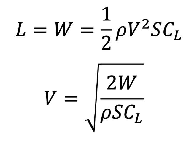
Straight and Level Assumptions
Velocity is constant
Altitude is constant
No acceleration --> Forces on body ∑ = 0
Velocity in Straight and Level Flight
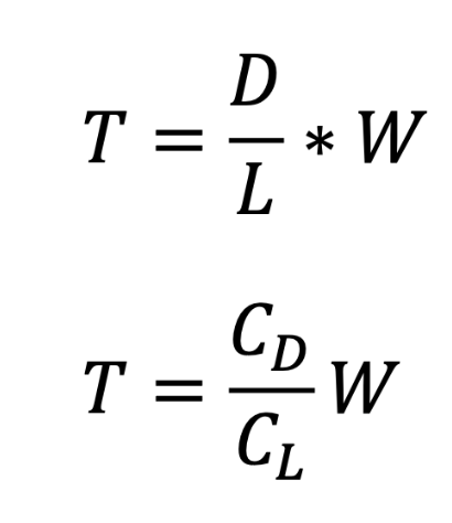
Thrust in Straight and Level Flight
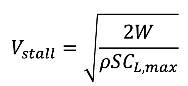
Stall Speed for Straight and Level Flight
Same as S&L velocity with the maximum CL
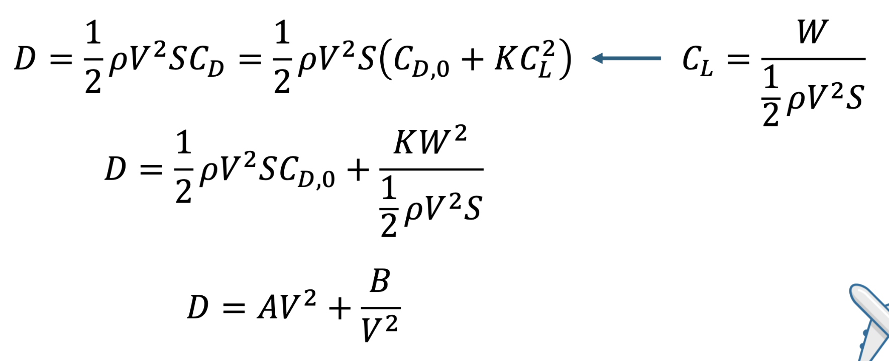
Straight and Level Drag Force
Uses the S&L assumption in plugging CL of a function of body weight (L = W in S&L flight)
Flight Envelope
Range of conditions between avaibale and required thrust —> physically possible thrust and velocity combinations
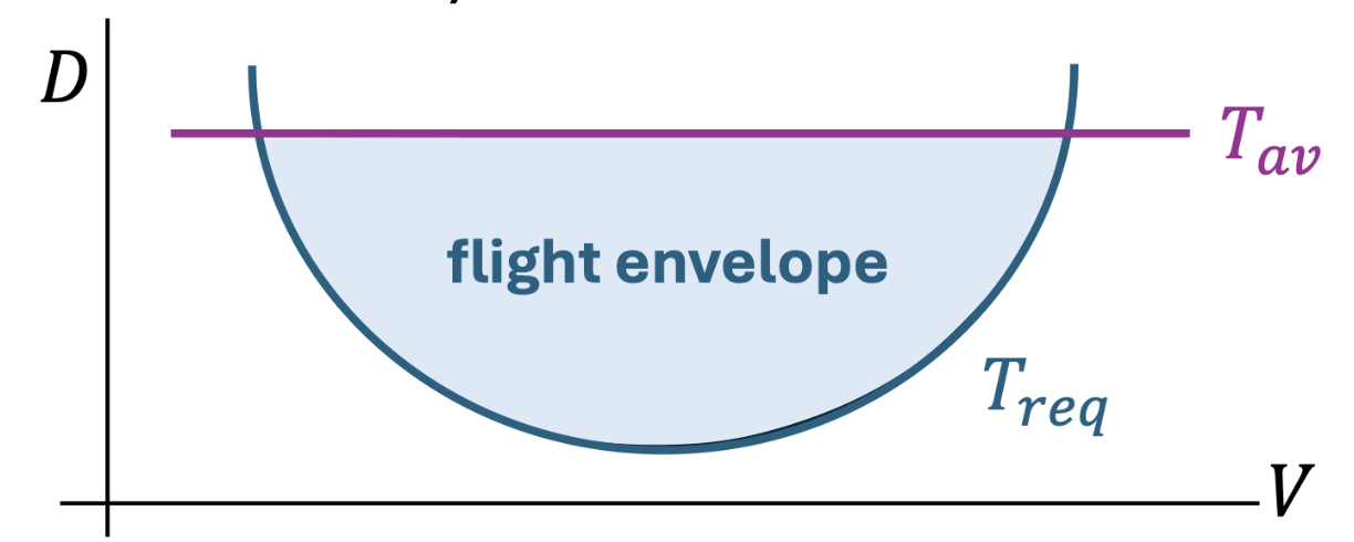
Thrust Available
Max amount of thrust an engine can produce
Thrust Required
Amount of thrust required based on drag
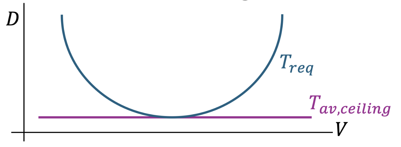
Ceiling
The maximum altitude that an engine can operate while still generating enough thrust to overcome the minimum drag
Higher altitude —> less thrust available —> min drag (convex point) > Tav —> plane can no longer move forward
Drag Polar
Combination of Parasite (Profile and Skin-friction), Wave, and Induced drag coefficients
Parasite: Split into zero lift and lift-dependent terms
Wave: Split into zero lift and lift-dependent terms
Induced: Prandtl’s Lifting Theory term
Designing with Drag in Mind
Drag is the sum of all of the air molecules resisting an object in motion
Cut down on the amount of drag so it takes less energy to move forward
Coanda Effect
Airflow will follow the shape of whatever it encounters
- Tendency of a fluid to remain attached to a curved surface
Representative of Newton’s Third Law — Equal and Opposite reactions
Airflow at trailing edge of the wing is shoved downwards, the downwards shove creates an equal and opposite upwards shove (lifting force on the wing)
Paper Airplane Design
Trade height for speed?
More forward center of gravity —> plane points more nosedown —> can gain speed that is lost from drag —> plane can gain enough speed to deflect off ‘winglet’ on back of plane pushing the tail of the plane down/lift nose —> create a balanced glide
Keep wide wingspan for effieicny to go farther
Sturdy/Structurally sound to handle the thrust
Winglets make wingtip vortices shed more cleanly, controls L/R roll — more stable in flight
Give front wing slightly higher angle of incidence —> front wing will stall first —> drops the nose of the plane —> main wing keeps flying
Wing Loading
Weight of whole plane divided by the lifting surface
High wing loading: plane must move much faster to lift the weight
Low wing loading: plane can move slower to lift the weight
For a constant weight, wing area is the factor changing the wing loading
Big wings slow, small wings fast
Glide ratio
L/D ratio
Stall
Caused by:
Too slow of airspeed
Too high angle of incidence (angle of attack)
Available Power in Flight
Thrust x velocity (TV)
Amount of power that can be provided to the aircraft
Required Power
Drag x velocity
Amount of power required in order to move forward as determined by the amount of drag at a given velocity
Excess Power
Available Power - Required Power
Specific Excess Power
Excess Power normalized by the weight of the aircraft
Excess Power during Climb and its uses
Can be used for:
Climbing faster
Change Speed
Do both of the above!
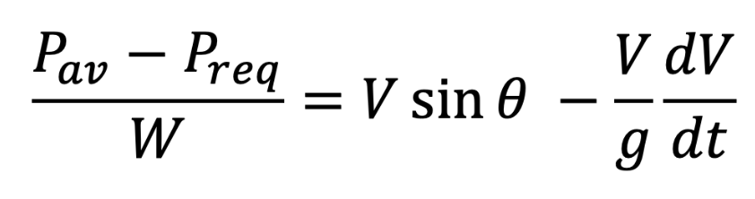
Altitude Change with Energy Conservation
Moving from some state 1 to state 2 in flight, based on energy conservation:
A relative decrease in state 2 velocity leads to a greater change in altitude
This means slowing down can allow (causality?) for an aircraft to climb
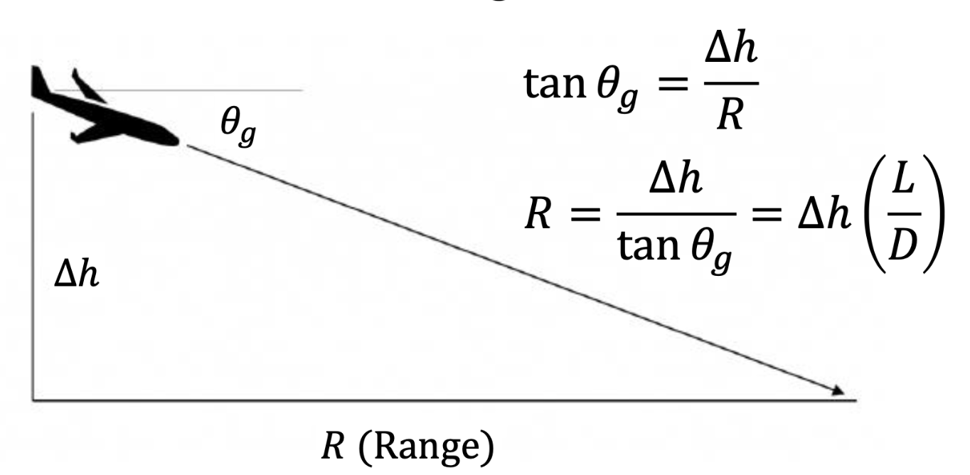
Glide Angle
dependent on the L/D ratio
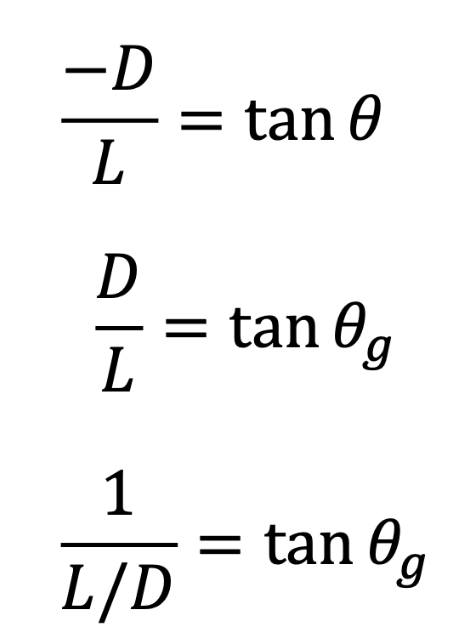
Glide Range
How far aircraft can travel with no thrust
Is a function of altitude and L/D ratio
Quasi-Level
Essentially the small angle approximation: angle from horizontal is <= 5˙
cos a ~= 1
For perp to flow: L - Wcos(a) = 0
—> L ~= W for Quasi-Level Flight
Planiform Surface Area
Outline of aircrafts wings as seen from above or below
Defines the leading edge, trailing, and chord lengths of the wing
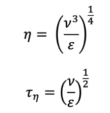
Kolmogorov Time and Length Scales
Used to characterize the smallest eddies within a flow
Defined by: kinematic viscosity and energy dissipation rate
Scales correspond to the point at which intertial forces and viscous forces of the flow are in equilibrium —> any smaller and the viscosity will overwhelm the eddy motion and it will dissipate entirely