Engineering Braking Systems
 Call Kai
 Learn
Learn Practice Test
 Spaced Repetition
 Match
Match Flashcards
 Knowt Play
1/90

Earn XP
Description and Tags
coppe
Name | Mastery | Learn | Test | Matching | Spaced | Call with Kai | Chat |
|---|
No analytics yet
Send a link to your students to track their progress
91 Terms
Historical Development of Braking Systems *in order ( CBB, D, D, AB, E E, RBS, A
Contracting Band Brakes
Drum Brake
Disc Brake
Anti Lock Braking System ( ABS )
Exhaust and Engine
Regnerative Braking System
Automotive Hand Break
Contracting Band Brake
In 1895, cars used contracting band brakes as pneumatic rubber tyrers made “block brakes” less effective
Had “Servo-assistance”
Servo Assistance- Brakes naturally tried to increase braking force
Advantage
Less damage of road debris
Disadvantage
Heat caused the drum to expand and drag againsnt the band
Not enough force for faster cars
Drum Brake
The shoes are lined with a friction material such as woven asbestos or a pressed asbestos composite
The shoes are enclosed in the drum, so the friction lining is away from water and dirt
Also has servo assistance
Hydraulically operated pistons opened the shoes, as the hydraulic cylinder was connected by piping to a master cylinder
DISADVANTAGE
Poor heat dissipation, difficulty to remove heat
Disc Brake
Most common type of brakes used in modern cars
Offers better heat dissipation other than drum brake
Offer wet weather performance as water is thrown off the disc by centrifugal force
Ventillated Discs to improve heat dissipation
Disadvantage
No servo-assistance, so that means the force at the pedal is very large. To reduce the effort the pedal force is boosted, a Vacum Booster is used.
Anti Lock Braking System (ABS) - More in Depth as a short answer question
It is a safety system that prevents the wheels from locking up during heavy braking.
Locking up- Wheels wheel stops rotating even though the car is still moving
It can lead to a loss of control and consequently accidents
MAIN INFO
In order for wheels to not lock up, it is achieved by “wheel sensors and computer control over the braking circuit”
1. The wheel begins to lock up, the wheel sensor will detect
2. Send a message to the computer
3. The computer will realease hydraulic pressure and allow the wheel to spin again.
It says ABS sensors are also used for:
Traction control → controls wheel spin during acceleration
Dynamic stability control → helps with handling and cornering
Exhaust and Engine Brakes
Engine Braking: Engine will tend to retard (slow down) the veichle
Exhaust Braking: Involves constricting the exhaust system
Regenerative Braking System ( Short Answer)
More environmentally friendly approach
In hybrid cars, the motor drives a generator that provides electricity to an electric motor. They also use batteries so in city areas the petrol or diesel motor does not need to run.
The advantage of this means that it is also possible to use electricity generation to slow the car.
The car’s kinetic energy is converted into useful electrical energy instead of being given off as heat energy.
ADVANTAGE
So instead of only using normal friction brakes:
the car can also slow down through electricity generation
Generator- Mechanical to Electric
Motor- Electric to Mechanical
Automotive Hand Brake
To hold a veichle in a parked position
Environmental Implications from the use of materials in Braking System
When asbestos breaks into tiny fibres, people can breathe them in. These fibres can get stuck in the lungs and may eventually cause lung cancer.
ASBESTOS
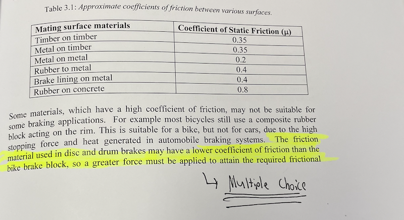
Friction
Mew= ff/rn
Friction from a ramp
Use calculation method
Break force into vertical and horizontal components
Use fx=0 and fy=0
Friction from Ground
Draw Diagram
Flipping R in bewteen frictional force and RN
Calculate angle
Draw all measurements then sine rule
Friction for Disc Brakes
2 forces acting on disc brakes
Refer to book
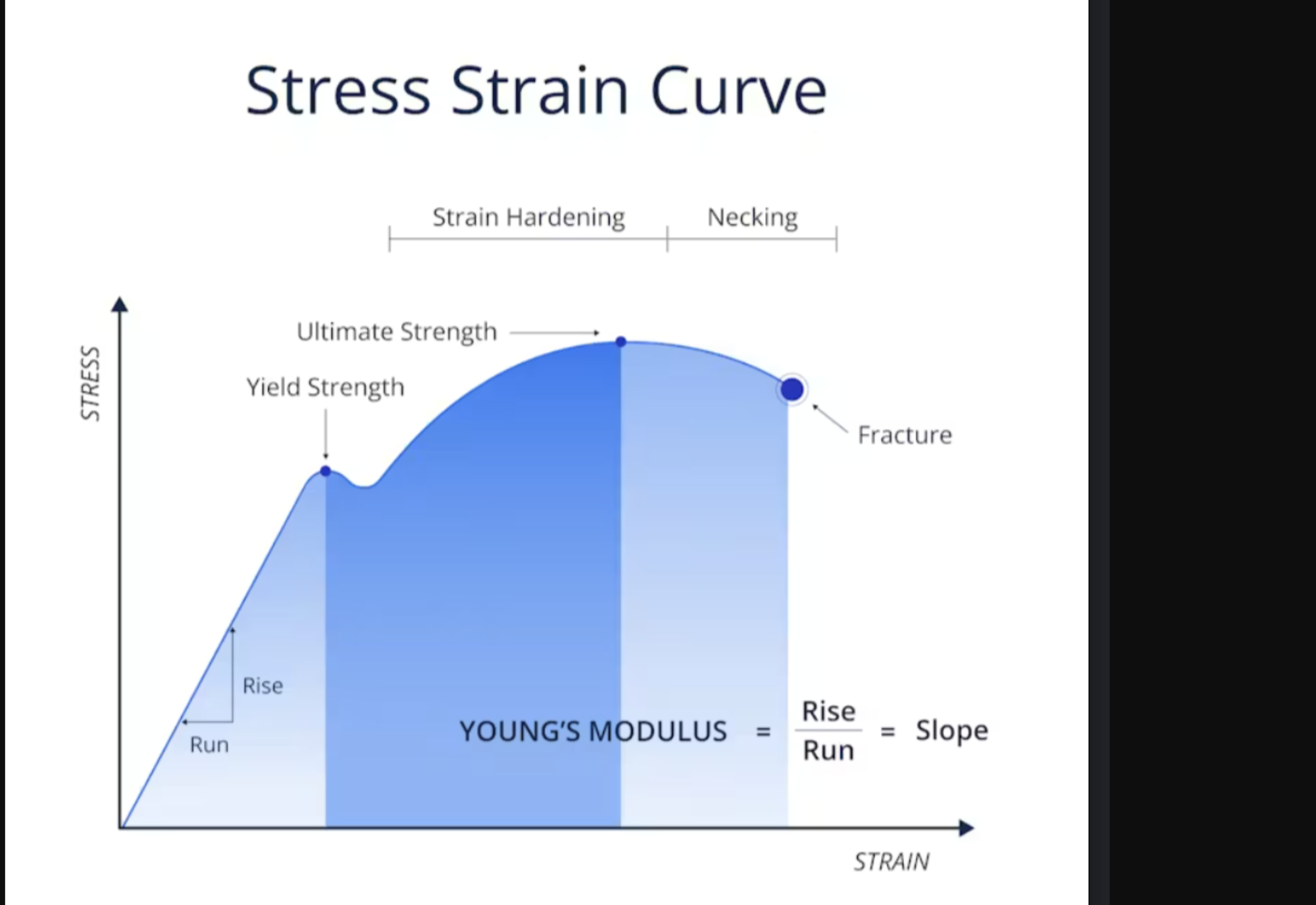
Stress
Stress= Force/ Area
MPA in mm2
Always convert KN to Newtons
Refer to book
Strain
Strain= Extension or shortening/ Original Length
As a decimal x100 to find percentage
Stress and Strain Diagram VERY IMPORANT
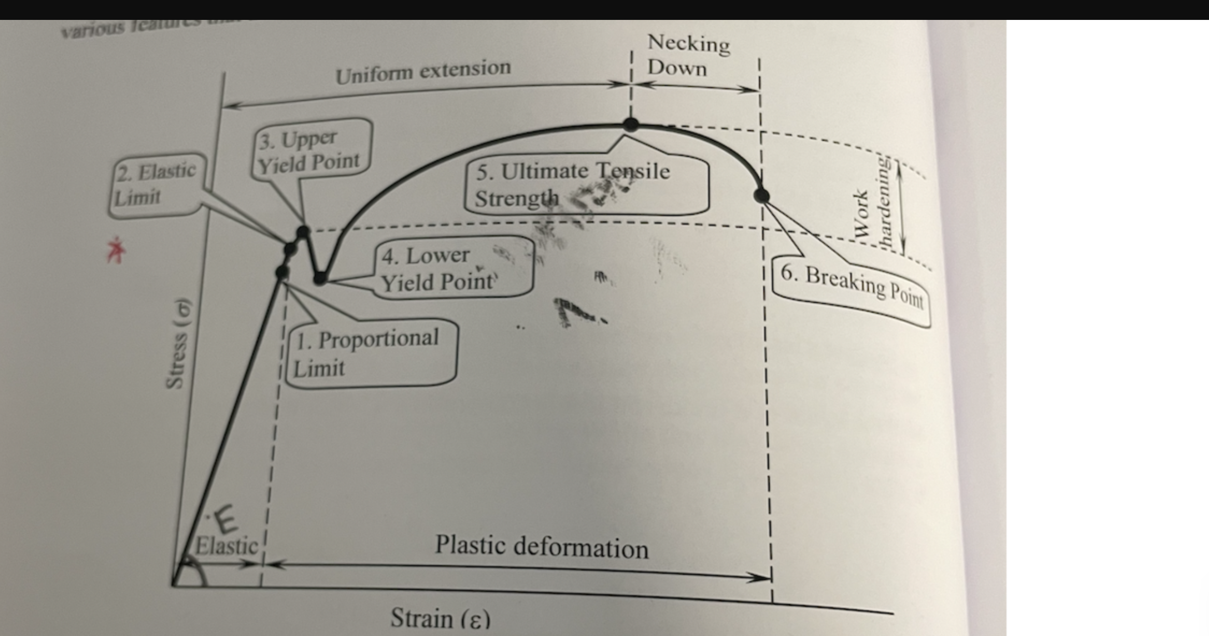
Features of Stress and Strain Diagram
Proportional Limit (Hookes Law)
- Straight line relationship between stress and strain
- E= STRESS/ STRAIN ( E = Young’s Modulus (Pa))
Elastic Limit
- Beyond this point plastic deformation will occur
Yield Points
- Increase in strain without an increase in stress
Ultimate Tensile Strength
- Maximum stress a material can withstand
Breaking Point
- The point the material will break or fracture

More features
Necking: Undergo localised deformation
Work Hardening: Increased strength and hardness with reduced ductility
Toughness: The area under the whole curve, resistance to shock loading
Resilience: The area under the curve ONLY in Elastic Deformation region
- It is also the amount of strain energy stored
Stiffness: The Young modulus, slope of the straigt line
BOLTS AND NUTS
height of nut= 0.
height of bolt= 0.
horizontal length nut
horinzontal lenhgt bolt
washer = 2 x d
Height of Nut= 0.8 D
Height of Bolt= 0.7D
Washer= 2 x Diameter
Horizontal length Nut= 1.8 D
Vertical Length Nut= 1.6 D
MATERIALS for Braking System
Steel
Steel
Binary alloy of iron and carbon
No more than 2 percent carbon
Steels are allotropic as is iron
Main structures in steel (A, F, C P
Austenite
Ferrite
Cementite
Pearlite
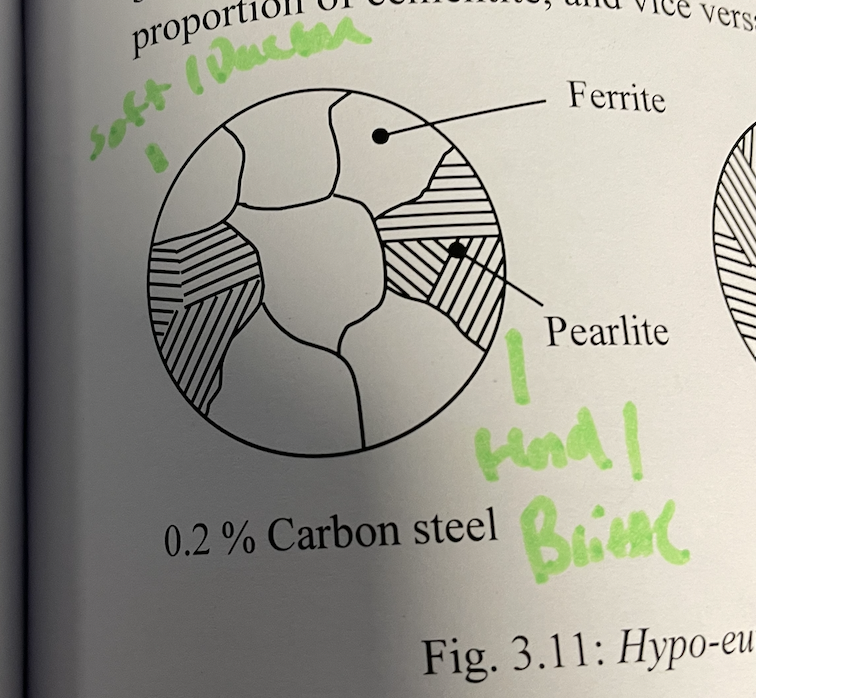
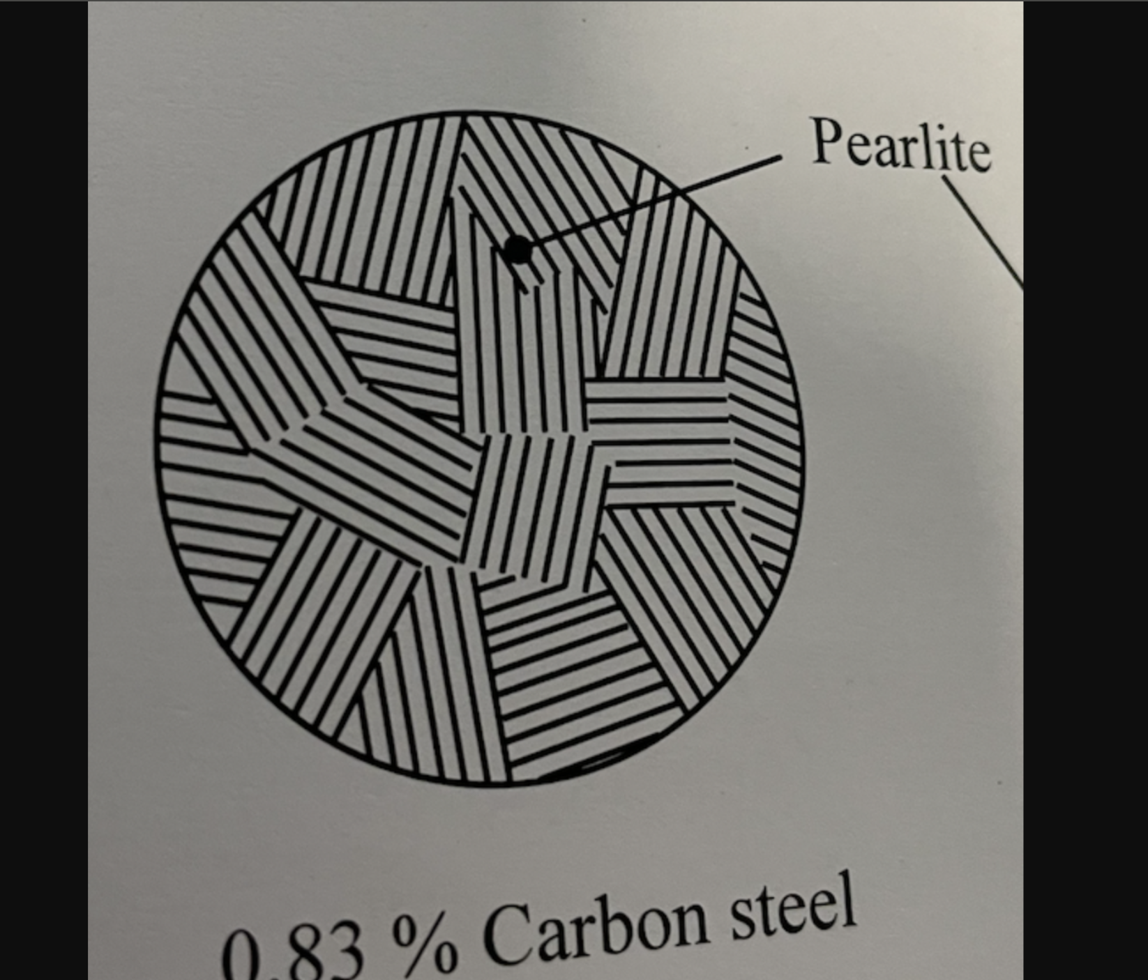
Diagram of 0.2, 0.83, 1.3 carbon steel percentages
Austentite
Also called “gamma” iron
Solid solution
When a steel is heated to red hot, it becomes austentite in structure
Ferrite
“Alpha” iron
Soft and Ductile
BCC structure present at room temp
Cementite
Iron Carbide
Increases Hardness at the expense of toughness and ductility, meaning more brittle easy to break
Pearlite
This material is called a euctoid structure
Forms when austentite cools to form two new solids
FERRITE + CEMENTITE = PEARLITE
0.2 PERCENT CARBON STEEL
More ferrite
Less pearlite
HYPO EUTECTOID
0.83 Percent Carbon Steel
ALL PEARLITE
EUTECTOID
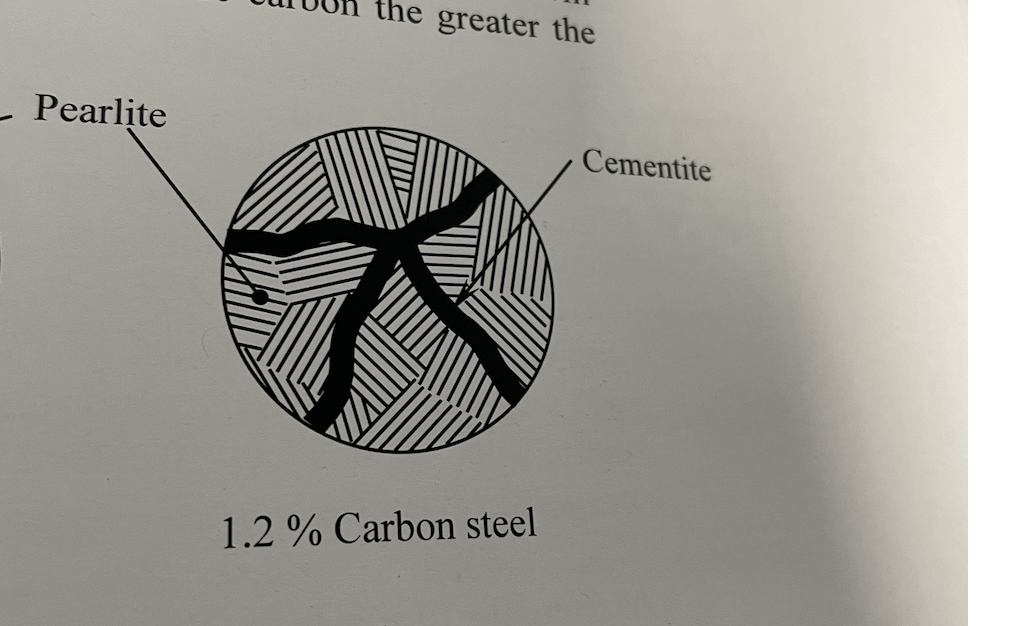
1.2 PERCENT CARBON STEEL
Pearlite and Cementite
HYPER EUTECTOID
Martensite
Martensite is when steel becomes heated until a Red Hot (FCC) stucture, then rapidly quenched to form a HCP Structure, resulting in the steel becoming very hard and brittle
Microstrutcure for Martensite
Microstructures used for under the microscope
Acicular Martensitte
Needle shaped form

Tempered Martensite
When martensite is reheated to make it less brittle, more tough, however retaining much of its hardness
200-600 degrees celcius
Low Alloy Steels
Steels that have other elements added to improve hardness, toughnesss and strength
Steels with less than 5 percent Alloying elements
Replaced carbon steels for many applicatations
List of elements added to “Low Alloy Steels”
( M, S, N, C, M, V, T, C , S, B, A , HSLA
Manganese
Suplhur
Nickel
Chromium
Molybdenum
Vanadium
Tungsten
Copper
Silicon
Boron
Aliminium
High Strength Low Alloy Steel (HSLA)
Manganese
Increase hardenability, making it more easy for it to be hardened
NOT “HARDER”
Hardness = how resistant the steel is to scratching, indentation, or wear.
Hardenability = how easily the steel can be hardened by heat treatment (such as quenching), and how deeply the hardness penetrates into the steel.
Sulphur
Combines with manganese, that produces good machining properties
Nickel
If added “2-5%”
- Improve toughness
- Impact resistance
If added “12-20%”
- Corrosion resistant steel is produced
Chromium
Improve wear resistance
Molybdenum
Improve hardnenability and increase strength properties at elevated temperatures
Vanadium (produces carb, and imporve elast
Produces carbides that are stable at higher temperatures
Improves elastic strength with little effect on ductility
Tungsten (tool)
Added to tool steels to improve their stability
Copper
Improve corrosion resistance
Silicon
USED FOR (3)
Same effect as Nickel
Used for:
High strength structured steels
Spring steels
Electricical grade steels
Boron
Has an immense impact on the hardenability of steels
Added in tiny percentages (0.001-0.003%)
Alimininium
Added to aid in nitriding a steel in amounts around 1 percent
High Strength Low Alloy Steels
HSLA
Improve yield strength and weldability
High Alloy Steels
(HAD… HIHH SPEE, STAIN
Hadfield Steel
High speed steels
Stainless Steel
Hadfield steel
- results in steel with ___ structure at room temp
Outside har__, isndie ___sof
example: Back…, excav
Uses manganese in quantities of 12 percent with 1.2 percent carbon
Results in a steel with an austentite structure at room temperature
Outside is hard, inside soft
Examples: Backhoe, excavator teetth, dredging equipment, rock breaking implements
High Speed Steels *4 values
18% Tungsten + 4% Chromium + 1% Vanadium + 0.75% Carbon
Stainless Steels
COVERED IN CHAPTER 4
Steels used in braking system
Push rods, caliper piston, brake pa
Of carbon steels, 0.1 to 0.3% carbon is used for braking system
Push rods, caliper pistons, brake pads, pad plates, shoes
Cast Iron
By definition a steel cannot excess 2 percent carbon
IF IT DOES
Cast iron are alloys that consist of iron with between 2.5 and 5 percent carbon, exceeding the 2 percent range
Why use cast iron?
cheap
goood strneh and rigi
easilt mach
greay fluid
It is a cheap material
Good compressive strength and rigidity
Easily machined
Great fluidity as it flows well in casting
Cast iron features “if mereley an alloy of iron and carbon”
Very hard
Very brittle
Needed when high wear resistance was required
Types of Cast Iron *5
W, G, H, SG, CG
White cast iron
Grey cast iron ( Pearlitc or Ferritic)
High Duty cast iron
SG (spheroidal graphite) Cast Iron
CG (compacted graphite) Cast iron
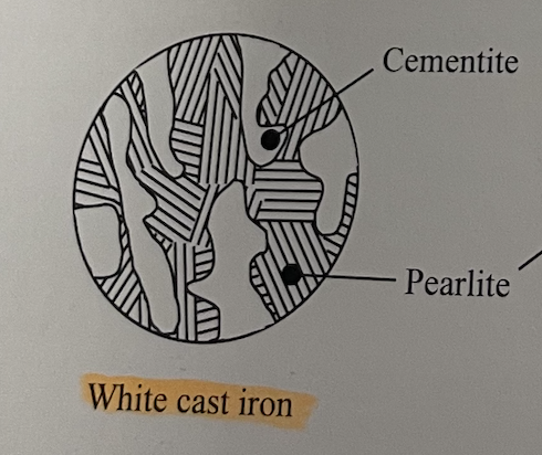
White Cast Iron, formed due to___
Formed due to fast cooling or low silicon
Grey Cast Iron formed of _____ high silicon
Result of high silicon content, and graphite forming as flakes
Grey cast iron features - VIBRATION, easily mach, stron in comp (3 advan, 1 disavdba
Weak in tension
Strong in compression
Easily machined
Excellent vibration dampening characteristics
Ferritic Grey Cast iron
Wholely ferrite with Large graphite flakes
Softer and weak
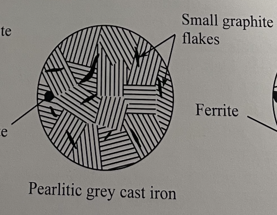
Pearlitic Grey Cast iron
Good toughness and good compressive strength
Used in Engine block, drum brakes, disc brakes
High Duty Cast Iron, act as stress con cent
They act as stress concentrations at the tip of the flakes and under a tensile load where cracks can occur
SG Cast iron ( Nodular or ductile iron)
- achieved by adding… mag or ceriu
improved TS
used in___
AKA Nodular or ductile iron
Achieved by adding small amounts of magnesium or cerium to the molten before casting
Improved tensile strength
Used in brake discs, drums
CG Cast iron
vibrat____
used in pump.. hou___
Their vibration damping peformance is double that of SG cast iron
Used in brake parts and pump housing
Malleable cast irons *white cast iron— remobve their…
White cast irons that have recieved further heat treatment to
remove their hardness and brittleness
replace them with toughness and improved tensile strength
3 types of Malleable cast iron
Blackheart Malleable Cast Iron
Whiteheart Mallaeable Cast Iron
Pearlitic Mallaebale Cast Iron
Blackheart Cast Iron (press edit flashcard to see whats its used for)
- heated in 900 in _____ environment for __ hours
- causes cementi. to break down
properties
- good cast..
- shoc..
- mach
used in: diff hous, suspensi ar
White cast iron heated to 900 degrees celcius in NO OXYGEN furnace for 48 hours
It causes the cementite to break down into graphite, which forms into temper carbon which is black in colour giving the name “Blackheart”
Properties:
- Good castability
- Shock resistance
- Machninability
Used in: Differential housings, suspension arms

Whiteheart Cast Iron , STRUCTURE
heated at ___degress for hours in an o_ environment
graphite diffu to surfac,, where replaced by __ __ gas
final structure : entirely f___
used in : high duc is req eg, pi
White cast iron is heated at 1000 degrees for 100 hours in an oxidising environment
The graphite diffuses to the surface where it is replaced with carbin dioxide gas.
Final structure: entirely ferrite
Used in: High ductility required such as pipes (ferrite is soft)

Pearlitic Cast Iron
- same metho as ___
high strn, good wea resis
Same method as “Blackheart cast iron”, then reheating to 900 degrees celcius
Highest strength and good wear resistant qualities

Composite Materials
offer high specif strng and desirb CR
Offer higher specific strengths and desirable corrosion resistance
Types of composties
Wood
Asbestos Lining
Sintered Metal composite
Wood
A natural composite
2.? what is it
Asbestos lining
Type of sintered metallic: Sintered Metal Composite
bendi…. met, kin
Bendix’s Metal King: Made up of iron powder, graphite and steel grit
Definite Yield
The graph shows a clear change from elastic behaviour to plastic behaviour
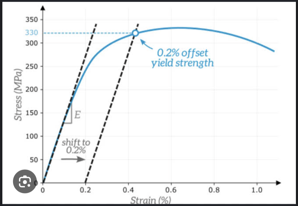
Indefinite Yield Graph
There is no obvious point where it changes from elastic to plastic behaviour
Manufacture of Brake Linings
first mix PFR, with addit, then moul
apply heat and press to promo p____
attaxh to steel pad using na adhe___
First mix phenol formaldehyde resin with additives then placing into a mould
Apply heat and pressure to promote polymerisation
Attached to a stell pad or shoe using an adhesive
Some high peformance brake pads include an insulating layer to reduce heat transfer
Testing of Materials ( 3 star very important) list 3 tests
tensi
comp
hard
Tensile Test
Compressive Test
Hardness Test
Tensile Test
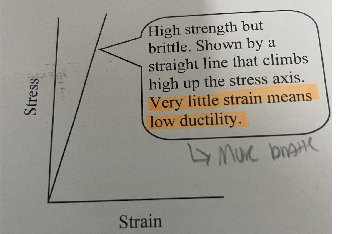
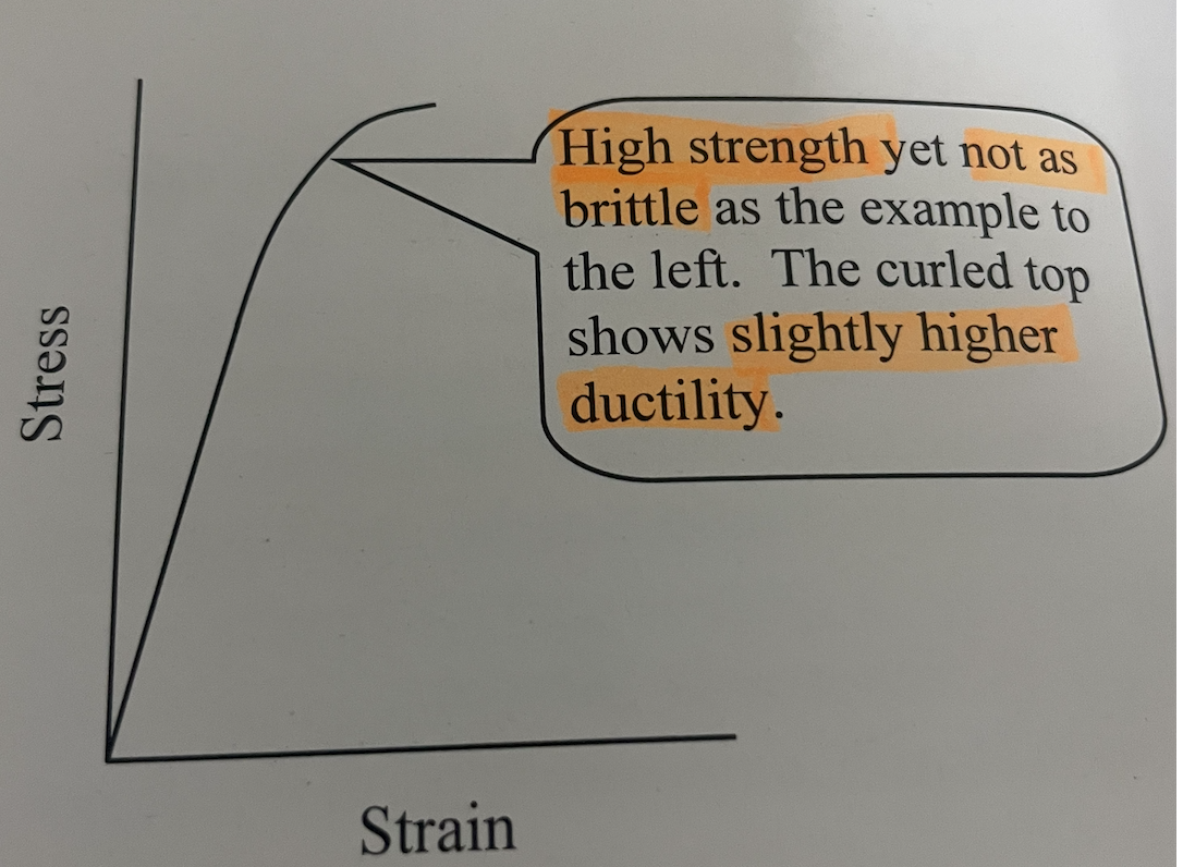
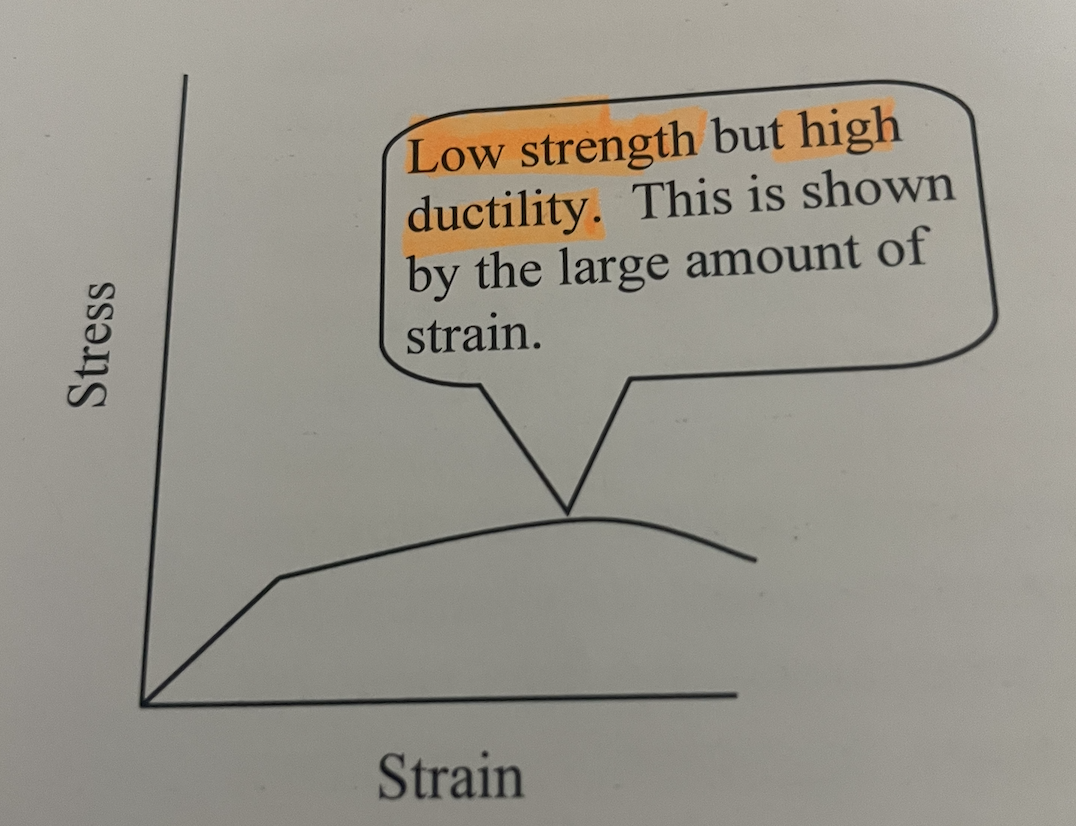
4 different diagram below
Higher stress= Higher stength
Higher strain= Higher ductility
More area under curver= toughness
1st Diagram
High strength
Brittle and not ductile
Very little strain means low ductility
2nd Diagram
High strength, not as brittle
Slightly higher ductility
3rd Diagram
Low strength
High ductility
4th Diagram
Moderate strength
High strain= More ductile
Toughness area under curve

Compression Test
*3
HF
SCF
SSPF
Hourglass fracture
Shear Cone fracture
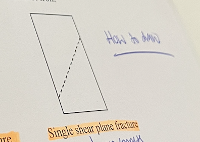
Single shear plane fracture
Hourglass fracture
Testing Concrete

Shearcone Fracture
Testing Concrete

Single shear plane fracture
Cast iron or concrete
Hardness Tests
B, V R, SS
Brinell
Vickers
Rockwell
Shore Scleroscope
Brinell (BSB) and how to determine hardness?
A hardened steel ball is forced into an object under load conditons
Hardness determinied = depth and surface
ANY MATERIAL
Vickers (VSP) (thick or thin
Square pyramid forced into object under load conditons
THIN MATERIALS
Rockwell (DS)
more useful for thick or thin metals
Diamond sphere forced into a object under load conditions
THICK
Shore Scleroscope
Small striker
Houndsfield Tensometer
Tensile test machine that peforms “tensile, compressive, shear and bending” tests.