Networking Mod 4 - 5 (copy)
1/166
There's no tags or description
Looks like no tags are added yet.
Name | Mastery | Learn | Test | Matching | Spaced | Call with Kai |
|---|
No analytics yet
Send a link to your students to track their progress
167 Terms
nodes
hosts and routers
links
communication channels that
connect adjacent nodes along
communication path
layer-2 packet
frame, encapsulates datagram
flow control
pacing between adjacent sending and
receiving node
error detection
• errors caused by signal attenuation, noise.
• receiver detects errors, signals
retransmission, or drops frame
error correction
receiver identifies and corrects bit error(s)
without retransmission
half-duplex and full-duplex
with half duplex, nodes at both ends of
link can transmit, but not at same time
sending side:
encapsulates datagram in frame
adds error checking bits, reliable data
transfer, flow control, etc.
receiving side:
looks for errors, reliable data
transfer, flow control, etc.
extracts datagram, passes to
upper layer at receiving side
single bit parity
detect single bit errors
two-dimensional bit parity:
detect and correct single bit errors
Even parity
set parity bit so there is an even number of 1’s
Internet checksum :sender
treat contents of UDP segment (including UDP header fields and IP addresses) as sequence of 16-bit integers
Internet checksum :sender
checksum: addition (one’s complement sum) of segment content
Internet checksum :sender
checksum value put into UDP checksum field
Internet checksum:receiver
compute checksum of received
segment
Internet checksum:receiver
check if computed checksum equals checksum field value: • not equal - error detected • equal - no error detected. But maybe errors nonetheless? More later
Cyclic Redundancy Check
more powerful error-detection coding
D: data bits (given, think of these as a binary number)
G: bit pattern (generator), of r+1 bits (given)
point-to-point
• point-to-point link between Ethernet switch, host
• PPP for dial-up access
broadcast (shared wire or medium)
• old-fashioned Ethernet
• upstream HFC in cable-based access network
• 802.11 wireless LAN, 4G/4G. satellite
Multiple access protocols
single shared broadcast channel
two or more simultaneous transmissions by nodes: interference
collision
if node receives two or more signals at the same time
channel partitioning
• divide channel into smaller “pieces” (time slots, frequency, code)
• allocate piece to node for exclusive use
random access
• channel not divided, allow collisions
• “recover” from collisions
taking turns
• nodes take turns, but nodes with more to send can take longer turns
TDMA: time division multiple access
access to channel in “rounds”
each station gets fixed length slot (length = packet transmission
time) in each round
unused slots go idle
example: 6-station LAN, 1,3,4 have packets to send, slots 2,5,6 idle
FDMA: frequency division multiple access
channel spectrum divided into frequency bands
each station assigned fixed frequency band
unused transmission time in frequency bands go idle
example: 6-station LAN, 1,3,4 have packet to send, frequency bands 2,5,6 idle
Random access protocols
when node has packet to send
• transmit at full channel data rate R.
• no a priori coordination among nodes
two or more transmitting nodes: “collision”
random access MAC protocol specifies:
• how to detect collisions
• how to recover from collisions (e.g., via delayed retransmissions)
examples of random access MAC protocols:
• ALOHA, slotted ALOHA
• CSMA, CSMA/CD, CSMA/CA
CSMA (carrier sense multiple access)
simple CSMA: listen before transmit:
• if channel sensed idle: transmit entire frame
• if channel sensed busy: defer transmission
human analogy: don’t interrupt others!
CSMA/CD: CSMA with collision detection
• collisions detected within short time
• colliding transmissions aborted, reducing channel wastage
• collision detection easy in wired, difficult with wireless
CSMA: collisions
collisions can still occur with
carrier sensing:
• propagation delay means two nodes
may not hear each other’s just-
started transmission
collision: entire packet
transmission time wasted
• distance & propagation delay play
role in determining collision
probability
CSMA/CD
CSMA/CD reduces the amount of
time wasted in collisions
• transmission aborted on collision
detection
channel partitioning MAC protocols
share channel efficiently and fairly at high load
inefficient at low load: delay in channel access, 1/N bandwidth
allocated even if only 1 active node!
random access MAC protocols
efficient at low load: single node can fully utilize channel
high load: collision overhead
“taking turns” protocols
look for best of both worlds!
“Taking turns” MAC protocols
polling:
master node “invites” other nodes
to transmit in turn
typically used with “dumb”
devices
concerns:
• polling overhead
• latency
• single point of failure (master)
token passing
control token passed from one
node to next sequentially.
token message
concerns:
• token overhead
• latency
• single point of failure
(token)
multiple downstream (broadcast) FDM channels
up to 1.6 Gbps/channel
single CMTS (cable modem termination system) transmits into channels
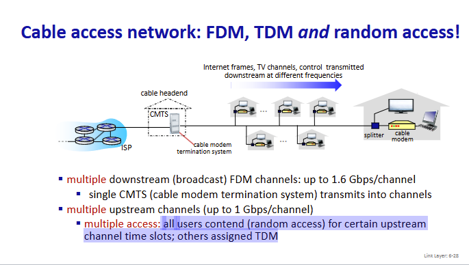
multiple upstream channels (up to 1 Gbps/channel)
multiple access: all users contend (random access) for certain upstream
channel time slots; others assigned TDM
multiple access
all users contend (random access) for certain upstream
channel time slots; others assigned TDM
DOCSIS
data over cable service interface specificaiton
TDM upstream:
ome slots assigned, some have contention
32-bit IP address
• network-layer address for interface
• used for layer 3 (network layer) forwarding
• e.g.: 128.119.40.136
MAC (or LAN or physical or Ethernet) address
• function: used “locally” to get frame from one interface to another
physically-connected interface (same subnet, in IP-addressing sense)
• 48-bit MAC address (for most LANs) burned in NIC ROM, also
sometimes software settable
hexadecimal (base 16) notation
(each “numeral” represents 4 bits)
• e.g.: 1A-2F-BB-76-09-AD
MAC addresses
each interface on LAN
has unique 48-bit MAC address
has a locally unique 32-bit IP address (as we’ve seen)
MAC address: like
Social Security Number
IP address:like
postal address
MAC flat address: portability
• can move interface from one LAN to another
• recall IP address not portable: depends on IP subnet to which
node is attached
ARP table
each IP node (host,
router) on LAN has table
IP/MAC address mappings for
some LAN nodes
< IP address; MAC address; TTL>
TTL (Time To Live)
time after which address mapping will be forgotten (typically 20 min)
Ethernet
“dominant” wired LAN technology:
first widely used LAN technology
simpler, cheap
kept up with speed race: 10 Mbps – 400 Gbps
single chip, multiple speeds (e.g., Broadcom BCM5761)
bus
popular through mid 90s
• all nodes in same collision domain (can collide with each other)
switched
prevails today
• active link-layer 2 switch in center
• each “spoke” runs a (separate) Ethernet protocol (nodes do not collide with
each other)
connectionless
no handshaking between sending and
receiving NICs
unreliable
receiving NIC doesn’t send ACKs or NAKs to
sending NIC
Ethernet’s MAC protocol
unslotted CSMA/CD with binary
backoff
Switch
a link-layer device: takes an active role
Switch
• store, forward Ethernet frames
• examine incoming frame’s MAC address, selectively forward frame
to one-or-more outgoing links when frame is to be forwarded on
segment, uses CSMA/CD to access segment
transparent
hosts unaware of presence of switches
plug-and-play, self-learning
switches do not need to be configured
switch learns which hosts
can be reached through
which interfaces
• when frame received, switch
“learns” location of sender:
incoming LAN segment
• records sender/location pair
in switch table
Interconnecting switches
self-learning switches can be connected togethe
routers
network-layer devices (examine
network-layer headers)
compute tables using routing
algorithms, IP addresses
switches
ink-layer devices (examine
link-layer headers)
earn forwarding table using
flooding, learning, MAC addresses
single broadcast domain
scaling: all layer-2 broadcast traffic
(ARP, DHCP, unknown MAC) must
cross entire LAN
efficiency, security, privacy issues
port-based VLAN
witch ports grouped (by
switch management software) so that
single physical switch operates as multiple virtual switches
traffic isolation
frames to/from ports
1-8 can only reach ports 1-8
• can also define VLAN based on MAC
addresses of endpoints, rather than
switch port
dynamic membership
ports can be
dynamically assigned among VLANs
forwarding between VLANS
done via
routing (just as with separate switches)
• in practice vendors sell combined switches
plus routers
trunk port
carries frames between VLANS defined over multiple
physical switches
MPLS capable routers
a.k.a. label-switched router
forward packets to outgoing interface based only on label
value (don’t inspect IP address)
• MPLS forwarding table distinct from IP forwarding tables
flexibility: MPLS forwarding decisions can differ from
those of IP
• use destination and source addresses to route flows to same
destination differently (traffic engineering)
• re-route flows quickly if link fails: pre-computed backup path
IP routing
path to destination determined by destination address alone
MPLS routing
path to destination can be based on source and
destination address
MPLS signaling
modify OSPF, IS-IS link-state flooding protocols to carry info used
by MPLS routing:
• e.g., link bandwidth, amount of “reserved” link bandwidth
entry MPLS router uses
RSVP-TE signaling protocol to set up
MPLS forwarding at downstream routers
Datacenter networks
10’s to 100’s of thousands of hosts, often closely coupled, in
close proximity:
e-business (e.g. Amazon)
content-servers (e.g., YouTube, Akamai, Apple, Microsoft)
search engines, data mining (e.g., Google)
Datacenter networks challenges
multiple applications, each serving
massive numbers of clients
reliability
managing/balancing load, avoiding
processing, networking, data
bottlenecks
Border routers
connections outside datacenter
Tier-1 switches
connecting to ~16 T-2s below
Tier-2 switches
connecting to ~16 TORs below
Top of Rack (TOR) switch
one per rack
40-100Gbps Ethernet to blades
Server racks
20- 40 server blades: hosts
Datacenter networks: multipath
rich interconnection among switches, racks:
• increased throughput between racks (multiple routing paths possible)
• increased reliability via redundancy
load balancer:
application-layer
routing
receives external
client requests
directs workload
within data center
returns results to
external client
(hiding data center
internals from client)
Datacenter networks: protocol innovations
Link layer
RoCE: remote DMA (RDMA) over Converged Ethernet
Datacenter networks: protocol innovations
transport layer
• ECN (explicit congestion notification) used in transport-layer congestion
control (DCTCP, DCQCN)
• experimentation with hop-by-hop (backpressure) congestion control
Datacenter networks: protocol innovations
routing, management
• SDN widely used within/among organizations’ datacenters
• place related services, data as close as possible (e.g., in same rack or nearby
rack) to minimize tier-2, tier-1 communication
wireless
communication over wireless link
mobility
handling the mobile user who changes point of attachment to
network
wireless hosts
laptop, smartphone, IoT
run applications
may be stationary (non-mobile) or mobile
base station
typically connected to wired network
relay - responsible for sending packets
between wired network and wireless
host(s) in its “area”
• e.g., cell towers, 802.11 access points
wireless link
typically used to connect mobile(s) to
base station, also used as backbone link
multiple access protocol coordinates link
access
various transmission rates and distances,
frequency bands
infrastructure mode
base station connects mobiles into
wired network
handoff: mobile changes base station
providing connection into wired
network
ad hoc mode
no base stations
nodes can only transmit to
other nodes within link
coverage
nodes organize themselves
into a network: route among
themselves
single hop
host connects to base station (WiFi, cellular) which connects to larger Internet
no base station, no connection to larger Internet (Bluetooth, ad hoc nets
multiple hops
host may have to relay through several wireless nodes to connect to larger Internet: mesh net
no base station, no connection to larger Internet. May have to relay to reach other a given wireless node MANET, VANET
Wireless link characteristics
decreased signal strength
radio signal attenuates
as it propagates through matter (path loss)
Wireless link characteristics
interference from other sources:
wireless network
frequencies (e.g., 2.4 GHz) shared by many devices
(e.g., WiFi, cellular, motors): interference
Wireless link characteristics
multipath propagation:
radio signal reflects off objects ground, arriving at destination at slightly different times