ACI 318/Reinforced Concrete
1/34
There's no tags or description
Looks like no tags are added yet.
Name | Mastery | Learn | Test | Matching | Spaced | Call with Kai | Chat |
|---|
No analytics yet
Send a link to your students to track their progress
35 Terms

LRFD strength reduction factor (Phi)
ACI Chapter 21 Strength Reduction Factors, Table 21.2.1
0.75 for shear
Typically 0.9 for flexural but depends on additional calc and ranges from 0.65-0.9
Need to use Table 21.2.2 to determine Phi factor based on strain values
To determine strain value, use similar triangles from stress block in Diagram/Figure below ACI Table or in Handbook
et = ecu * (d-c) / c (derived from similar triangles eqn)
c = kd = a/Beta
Beta = ratio of a/c, Handbook Concrete section definitions table with compressive strength values
And a can obviously be calculated from main equation in Handbook a = (As*Fy) / (.85*f’c*b)
kd is in Handbook 4.3.2.3 diagram where it gives kd/3 instead of c/3
k and j are just random factors for the stress block
j is typically 0.9
Can use kd whenever a and Beta can’t be determined
Per Table, have to interpolate using equations in Table if et is between ety and .005
Between .45 and .75 for anchors dependent on Chapter 17
17.3 General requirements for strength of anchors, 17.3.3 Strength Reduction Factors there’s a list/table
Note that the Categories (for medium reliability, etc.) should be considered in addition to general cases a-c
Total Concrete Shear strength
22.5, Vu < phi*Vn = phi*Vc + phi*Vs
Vc Depends on if one-way or two-way shear, check maximums and minimums in each section
For one way shear, 22.5.5
For two way shear, depends if shear reinforcement installed
If no shear rebar, 22.6.5
If shear rebar installed, 22.6.6
Vs also depends on one-way vs two-way shear
One way, 22.5.10 - Vs = Av * fy * de / s, only if transverse reinforcement, typically have to iterate for this
Max = 4*sqrt(f’c)*bw*de, from Table 9.7.6.2.2 which is reinforcement limits for transverse shear reinforcement
If provided ultimate demand load Vu and either Vc or Vs, you can calculate the unknown Vc or Vs using the total Vn equation
Can also use this equation to solve for max shear reinforcement spacing if you know the demand to be resisted by the rebar
Note that stirrups ONLY help in Shear and longitudinal bars ONLY help in Tension. Realistically they contribute through shear friction but we don’t account for it
Two way, 22.6.7, Vs = (Av*fy) / (bo*s)
Normal weight concrete vs lightweight concrete
Lambda = Concrete weight reduction factor
1.0 for normal weight
0.75 for lightweight
Density
150pcf for normal weight
115pcf for lightweight
Over reinforced concrete beam failure
Over reinforcing a concrete beam will result in sudden crushing failure on the compression side of the beam, which is unsafe and not recommended
Instead, we want the steel tensile strength on the tension side of the beam to be less than the compressive strength of concrete so the steel yields first which allows a slower, safer failure
Deformed rebar
Steel bars with ribbed edges to enhance grip/tension with concrete
Concrete mix design
Most is in Chapter 19 Concrete design and durability requirements (air content, w/cm ratio, lambda values, etc.)
Except max aggregate size which can easily be found with a Ctrl+F but is in ACI 26 Construction Documents and Inspection, 26.4 Concrete Materials and Mixture Requirements, 26.4.2 Concrete Mixture Requirements
The max agg size will be a fraction of the distance b/t forms, slab thickness or clear spacing b/t rebar
Intent of a max agg size is to encourage wet concrete workability to prevent air pockets and honeycombing
Interaction
When a component is under both tension/moment and shear loads, most typical for an anchor bolt
V/Vallow + T/Tallow < 1.0
ACI 17.6 - Anchoring to Concrete, Interaction of Tensile and Shear Forces
ACI states throughout pretty much each design section of the codebook that interaction must be considered when it applies
How to determine (Icr) Cracked Moment of Inertia
Just Ctrl+F Icr
For a beam zero out the Pu term completely since there’s no axial load
Icr considers a more realistic I for cracked concrete, taking 2 blocks/sections (a tension and compression) into account
Transforms rebar area into equivalent concrete area using the modular ratio Es/Ec
Icr technically derived from parallel axis theorem, didn’t spend time to figure out derivation though

How to determine flexural strength of reinforced concrete beam?
Determine governing allowable tensile or compressive force * lever arm (distance between tensile/compressive forces)
Handbook, Mn equations
Lever arm = d-a/2

How to find design punching shear force capacity Phi*Vn for a column bearing on a concrete spread footing?
This failure is like someone literally punching through something, so the strength actually lies in the critical perimeter of the footing around the column and the depth of the footing
ACI 22.6.4.1 describes critical perimeter of footing around column = bo = SUM of all column widths/lengths with the footing depth added to each width/length
Punching shear force capacity = concrete two way shear strength from 22.6 * critical perimeter (b0) * effective depth (de)
Similar process for elevated/suspended slabs, but changes as described below for drop panels and shear caps that meet ACI’s standards in 8.2.4 and 8.2.5, noting that the alpha and beta values in the two way shear strength equation will also change accordingly:
For drop panels (making the slab slightly thicker a large distance around the columns) the slab will still fail right around the column. So the thickness increases but the critical perimeter stays the same.
For shear caps (making the slab significantly thicker a small distance around the columns) the slab will fail De/2 outside of the shear cap now. So the critical perimeter increases but the thickness stays the same.

Meaning of Rebar Markings
First letter/symbol is the manufacturer
The first number is the bar size/#
The second letter is the steel type
S = Carbon steel A615
Stronger than A706
W = Low alloy steel A706
Higher ductility so better for seismic than A615 and better weldability than A615
A = Axle steel A996
SS = Stainless steel A955
CS = low carbon chromium A1035
The second number is the grade mark or the yield strength like 60ksi

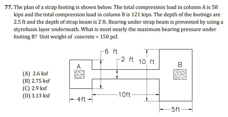
How to analyze a strap footing?
The pressure under each spread footing equals the SUM of the download forces on the footings divided by the total footing/bearing area (not including the strap footing area)
A strap footing is really like a reinforced concrete beam installed over spray foam between (2) spot footings. The footings act uniformly so that the total force from both footings is combined and the pressure under each footing is equivalent

How to find required flexural strength of footing supporting column with given axial load?
Get soil bearing pressure = column Force / footing Area
Now think of punching shear and where footing would fail, at column edges. The footing portions not below the column would experience an upward curling movement like cantilevered beams
So find Mmax for a theoretical cantilevered beam (Mmax = w * L² / 2 per handbook)
L = largest footing edge not below column = (largest footing width - column width) / 2
w = soil bearing pressure in force per ft²
That is the Mmax per foot, for a 1’ wide strip of the concrete footing. To get the required flexural strength for the whole thing we would multiply Mmax by the other footing width direction

Minimum rebar
Typically this will be 0.0018 * Ag
Where Ag is the gross area of concrete section = width times thickness/depth

How to find flexural demand on heel of retaining wall?
Critical section is at transition from heel to wall edge where the heel would break off
Do sum of moments at critical section considering heel weight, soil weight, and any surcharge load
LRFD - Per ACI 5.3.8 if lateral earth pressure (retained soil) is present, it should have a 1.6 load factor
ASD - Factor Of Safety 1.5

Concrete mix design
Type 1 = Normal application
Type 2 = Sulfate resistant/exposed concrete, like to water or soil
Type 3 = High early strength
Type 4 = Low heat of hydration, used for giant structures
Type 5 = Severe sulfate conditions
Superplasticizer = reduces water/cement ratio so more durable and less permeable, good for coastal exposure, also enhances workability
Chemical accelerator = accelerates curing time and increases early strength, BAD for coastal
How to determine the allowable compressive and tensile forces of a reinforced concrete beam?
Cc = .85*f’c*b*a
.85 is the factor that has been field tested to represent the actual strength of the concrete when compared to laboratory concrete
Then it’s just multiplying the effective concrete compressive area by the compressive strength f’c of concrete, where b is the width of the concrete beam and a is the depth of the stress block
Ts = As*fy
As is the total combined area of steel
fy is the tensile yield strength of steel, typically 60 kips/in²
These forces should be equal and opposite of one another, that’s how we can solve for the required area of steel (As) or the depth of the stress block (a)
How to find total top OR bottom end fiber stress at release at the midspan of a reinforced concrete beam with prestressed rebar installed at the bottom 1/3 of the beam, provided the individual rebar size and stress at release per bar?
See Figure 5.2.5 from PCI handbook, but the total stress at the top fiber = Compressive Paxial + Pbending
Paxial is the axial compressive force from the released prestressed rebar pulling inward = Combined compressive force from all rebar strands stress at release / beam area
Combined compressive force = stress at release per strand (ksi) * As (total area of steel reinforcement)
Pbending is the bending stress which would be tensile at the top of the beam from the released prestressed rebar pulling inward at the bottom of the beam causing the beam to frown, or compressive at the bottom of the beam from the same effect = combined compressive axial force from stress at release * lever arm from rebar N.A. to beam section N.A. / beam section modulus
The eccentricity or lever arm is from the rebar N.A. to the beam’s geometric N.A. (aka just the very center, not the flexural N.A.), because that is it’s effect on the cross-section
Section modulus for simple beam can be simple bd²/6 but if integrated with slab or something then must use S = I/c, where c = distance from beam section N.A. to top or bottom edge depending on analysis required
If the beam self dead weight or live loads are to be considered then you would increase the tensile bending stress by the beam dead/live load tensile bending stress = load * eccentricity from beam section N.A. to top or bottom of beam / section modulus
How to determine nominal strength of rebar anchor in tension?
ACI Chapter 17 Anchoring to Concrete, 17.4 Design Requirements for Tensile Loading gives an equation for nominal strength of an anchor in tension = A*futa
futa = specified tensile strength of steel anchor, and this section gives limits that futa can’t exceed 1.9fya or 125,000psi
fya = specified yield strength of steel anchor (for grade 60 rebar that is just 60,000psi)
How to determine minimum thickness of a suspended concrete one-way slab?
ACI 7.3.1.1 gives minimum thickness per slab length
Note that for a multi-span slab we would likely just take the calculated governing/thickest portion of the slab
How to determine location of the Neutral Axis of a cracked concrete section?
Use handbook concrete equations to solver for c or kd depending on what information you’re provided
c equation uses a and Beta
kd equation uses p (ratio of steel area to concrete area) and n (modular ratio)
Modulus of elasticity for concrete comes from ACI Chapter 19 Concrete Design Requirements
How to determine max allowable initial concrete beam deflection to prevent damage to cosmetic components attached to the beam from long term (5+years) creep/deflection?
Use ACI Chapter 24 Serviceability Requirements, 24.2 deflections from service-level gravity loads
Table 24.2.2 Max Allowable Deflections, gives total allowable deflection limits
24.2.4 Time dependent deflections, gives equation for creep factor
Note that per Chapter 2 terminology/definitions, p’ = A’s/(b*de) which A’s is for the compression reinforcement only, because the bottom/tensile steel doesn’t contribute to preventing long term deflection at all
Note that steel is IMMUNE to creep/long term deflection, while concrete and wood are very susceptible
Compression reinforcement helps to stiffen the upper half of the beam and helps prevent sagging/creep from sustained loads
Use explained equation in 24.2.4.1.1 creep paragraph that total long term deflection = initial deflection * creep factor, and solve for initial deflection since total long term deflection = max allowable deflection from deflection limits table
What is a prismatic member?
Uniform member, meaning it doesn’t have variable depth
How to determine max factored negative moment in a continuous one way slab spanning across 5 integrated concrete beams with dead/live load psf provided using the simplified method of analysis?
Ctrl+F “Negative Moment” in ACI, Table 6.5.2 from Chapter 6 Structural Analysis, 6.5 Simplified Method of Analysis for Nonprestressed Continuous Beams and One Way Slabs
Have to first verify all parameters in 6.5.1
Then just use table and most conservative equation (that would create the highest/maximum moment), typically will be wl²/10
See subnote 1 that the length Ln to be used is the avg of the adjacent CLEAR SPANS for negative moment only
How to determine effective flange width for concrete T-beams poured integrally with a slab?
ACI 6.3.2 has a Table for this
Note that table only gives effective “overhanging” flange width for one side of web, so multiply it by 2
Add the overhanging flange width from each side of T-beam to beam width bw to get effective flange width bf
Define different ACI L terms
Beams
l = length from support centerline to centerline
ln = clear span length
Columns
lc = height length from support centerline to centerline
lu = clear height length
How to determine the column slenderness ratio for a multi-bay moment frame?
ACI 6.2.5 gives slenderness ratio (k*l/r) limits for moment frame vs braced frame
Figure R6.2.5 gives effective length factor k
Have to calculate Greek letter psi based on SUM(E*I/L)columns / SUM(E*I/L)beams
Pinned connection = Greek letter psi of 10
Rigid connection = Greek letter psi of 1.0
I = effective MOI which comes from Table in 6.6.3
Lu for columns is the clear span height
r equation is given in this section but it’s also allowed to be taken as 0.3*column width in direction stability is being considered
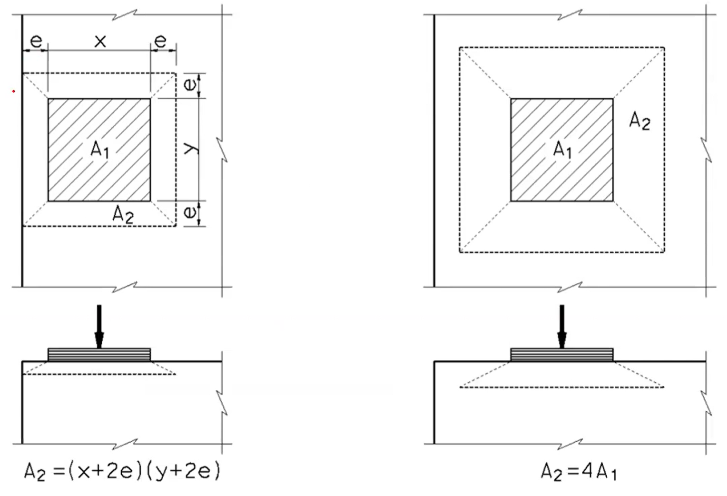
How to determine bearing strength of a concrete pedestal for a beam resting on it?
ACI Chapter 22 Sectional Strength, 22.8 Bearing Strength
Use equations from Table 22.8.3.2, and diagrams below for A1 vs A2
The max A2 area is 4*loaded area (A1). If the beam is closer than that max area to the support edge then all side lengths of A2 are reduced to be the actual loaded area plus whatever the minimum dimension is
How to determine required spacing of transverse tie bars with given bar size in a concrete column that is loaded with axial and shear/lateral loads?
Rearrange the total reinforced concrete sectional shear strength equation from Chapter 22 Sectional Strength, 22.5 One-way Shear Strength, 22.5.1 to solve for Vs
Note that because we are checking the shear strength that phi will be according to shear and not axial, even though axial is more conservative and is applied
Vc equation comes from 22.5.6 Vc for nonprestressed members with axial compression
Note that there are 5 different categories of concrete shear strength Vc ranging from 22.5.5 through 22.5.9 based on loads and nonprestressed vs prestressed
Check that Vs is less than the max limit from Chapter 22.5.1.2
Rearrange the steel shear strength equation from ACI 22.5.10 One-way Shear Reinforcement, 22.5.10.5 One-way Shear Strength Provided by Transverse Reinforcement to solve for the s
Note that for transverse tie bars (rebar that makes a complete square around the square column) we will count 2 of the sides as contributing rebar area because if the concrete column cracks down the middle only 2 of them will help hold it together in tension, so As = 2*individual bar area
Check max spacing limit from Chapter 10 Columns, 10.7 Reinforcement Detailing, 10.7.6 Transverse reinforcement, 10.7.6.5 Shear
Never need to check the minimum transverse reinforcement spacing limit because it’s typically going to be 1-2”, which we would never recommend
How to determine the design strength in shear friction at the reinforced joint between a concrete column and footing?
Use equation in Chapter 22 Sectional Strength, 22.9 Shear Friction Strength, 22.9.4.2 gives strength equation
Remember to add any permanent vertical dead load to JUST the Avf*fy part of the equation = (Avf*fy + Pd)*mew*phi
Also check max/upper limit from 22.9.4.4, remember to apply the phi reduction factor though because it doesn’t show it
How to determine the required positive flexural As for a beam to column joint in a special moment frame, provided the required negative flexural As?
Chapter 18 Earthquake Resistant Structures, 18.6 Beams of special moment frames, 18.6.3 Longitudinal reinforcement
Says that positive flexural strength must be ½ negative flexural strength, so you can just divide the required negative flexural As by 2 because the Mn equation is directly proportional to As
How to determine required development length for bars in tension?
Use governing equation from 25.4.2 that requires the longest/greatest development length (likely 25.4.2.2)
Bars in tension will typically be longitudinal bars
The concrete cover measurement is based on the cover for the developed portion of the bar in the joint where it is developed, NOT the cover measurement in the origin member
How to determine concrete breakout strength for a cast in place anchor in tension?
Get phi factor from 17 Anchoring to concrete, 17.3 General requirements for anchor strength, 17.3.3 gives table with phi factors
Depends if supp. reinforcement, etc.
Breakout strength per 17.4.2 Design requirements for tensile loading
Lambda “a” is still just lightweight concrete adjustment factor
NOTE that Heff embedment depth is the distance from the concrete to the closest edge of the anchor’s head/tail/leg
Depends on if anchor is close to an edge or not
How to determine tensile pullout strength of J-bolt anchor?
Get phi factor from 17.3.3
Pullout strength per 17.4.3 Design requirements for tensile loading
Note that eh (the length of the j-bolt’s tail/leg) does not include the anchor diameter, and there’s a max/min limit for it
How to find max spacing of stirrups in a beam provided applied factored shear load and beam dimensions?
Chapter 9 beams, 9.7 Detailing, 9.7.6 Transverse reinforcement, Table 9.7.6.2 gives max spacing
Can solve for Vs using the Vu = Phi*(Vc+Vs) equation, and filling out Vc based on 25.5.5