3 in 1 phone
1/112
There's no tags or description
Looks like no tags are added yet.
Name | Mastery | Learn | Test | Matching | Spaced | Call with Kai |
|---|
No analytics yet
Send a link to your students to track their progress
113 Terms
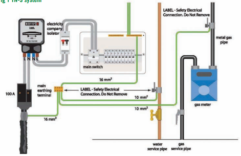
What is a TNS system, what is its disconnection time and what is its earth fault loop impedance?
T = Terra (earth connected at the source)
N = Neutral connected to earth at the source
S = Separate earth and neutral conductors
In a TN-S system, the line and neutral are provided as separate conductors from the supply transformer, and the earth is provided by the metal sheath of the supply cable, which is earthed at the source to provide a path for fault current.
The maximum disconnection time is 0.4 seconds for final circuits and 5 seconds for distribution circuits. These disconnection times apply regardless of whether an RCD is used, although an RCD may be required to achieve these times.
Typical external earth fault loop impedance (Ze) value is around 0.8Ω
What is a TN-C-S system, what is its disconnection time and what is its earth fault loop impedance?
Terra-Neutral-Combined-Separate
In a TN-C-S system, the supply provides a line conductor and a combined protective earth and neutral (PEN) conductor from the transformer to the service head. At the service head, the PEN conductor is separated into neutral and earth. This system is also known as PME (Protective Multiple Earthing), as the neutral is earthed at multiple points along the supply network, instead of the all fault current entering the PEN conductor at a singular point. In the event of a fault, current flows through the circuit protective conductor (CPC) and returns via the PEN conductor to the source, causing the protective device to disconnect the supply.
The maximum disconnection time is 0.4 seconds for final circuits and 5 seconds for distribution circuits. These times apply regardless of whether an RCD is used, although an RCD may be required to achieve them.
Typical external earth fault loop impedance value is around 0.35Ω
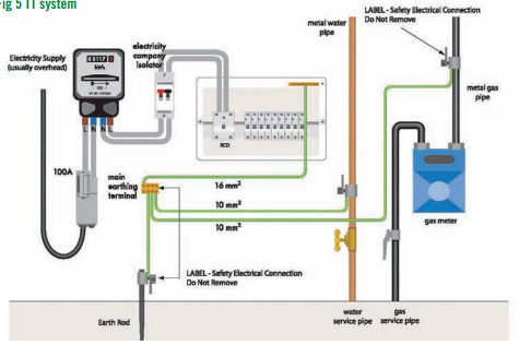
What is a TT system, what is the disconnection time and what is its earth fault loop impedance?
First T = The transformer neutral is connected to Terra (earth) at the source
Second T = The installation is connected to its own local earth (Terra) via an earth rod.
In a TT system, the supply provides a line and neutral conductor only, and the installation earth is connected to a local earth electrode, such as a rod or plate, rather than the supply earth. In the event of a fault, current flows through the earth electrode and returns through the general mass of earth to the source. Due to the high earth loop impedance, an RCD is required to provide automatic disconnection of supply.
The maximum disconnection time is 0.2 seconds for final circuits and 1 second for distribution circuits when protected by an RCD.
Typical external earth fault loop impedance value is around 200Ω
What is the difference of PEN and PME for a TNC-S system?
PEN - (Protective earth neutral) Combines neutral and earth conductor
PME - (Protective multiple earths) The system using pen conductor with multiple earthing points.
What is Earth fault loop impedance, is it a live or dead test, what test equipment is used and how is it tested?
Zs (earth fault loop impedance) is measured at the furthest point of a circuit and represents the total impedance of the earth fault loop, including both the supply and the installation. It verifies that the fault current path is low enough to allow protective devices such as fuses or circuit breakers to disconnect the supply within the required time under fault conditions. This is a live test, carried out with the circuit energised using an RCD-compatible loop impedance tester connected between line and earth at the point of test. The measured value is then compared with the maximum permitted value from the regulations. A low Zs value ensures sufficient fault current flows for fast disconnection.
Ze (external earth fault loop impedance) is measured at the origin of the installation and represents the impedance of the supply earth path only. To measure Ze, the supply is first isolated and the main earthing conductor is disconnected from the main earthing terminal to avoid parallel paths. The tester is then connected between line and earth, with a probe connected to the line conductor and a secure connection, such as a crocodile clip, connected to the main earthing terminal. The supply is briefly restored to obtain the reading, making this a live test. The main earthing conductor must be reconnected immediately after the test.
R1 + R2 is the resistance of the line conductor and the circuit protective conductor within the installation. It is measured on a dead circuit using a continuity tester. Line and CPC are connected together at the distribution board, and resistance is measured between line and earth at the furthest point of the circuit. This value represents the resistance of the conductors forming the fault path within the installation.
Zs can also be calculated using the formula:
Zs = Ze + (R1 + R2)
where Ze is the external earth fault loop impedance, R1 is the line conductor resistance, and R2 is the circuit protective conductor resistance.
What is prospective fault current, is it a live or dead test, what test equipment is used, what is the resulhow is it tested?
The purpose of a prospective fault current (PFC) test is to determine the maximum possible fault current at a point in the installation, ensuring that protective devices can safely withstand and disconnect it. This is a live test carried out with the supply energised using a loop impedance tester, often part of a multifunction tester (MFT).
The prospective short-circuit current (PSCC) is the maximum current that could flow during a short circuit between live conductors, such as line–neutral in a single-phase system or line–line in a three-phase system.
The prospective earth fault current (PEFC) is the maximum current that could flow between a live conductor and earth.
Both PSCC and PEFC are measured during the test, and the higher value is recorded as the prospective fault current (PFC) on the schedule of test results. These values are typically expressed in kiloamps (kA).
PFC can be calculated using Ohm’s Law (I = V / Z). For earth fault current, the formula is:
I = V / Ze
For a line-to-neutral fault, 230 V is used. For a line-to-line fault in a three-phase system, 400 V is used and the current is calculated by dividing by √3 times the impedance:
I = 400 / (√3 × Z)
What is continuity of CPC, is it a live or dead test, what test equipment is used and how is it tested?
The continuity of protective conductors test is a dead test carried out to verify that the circuit protective conductor (CPC) is continuous and correctly connected throughout the circuit. With the supply safely isolated, a low resistance ohmmeter/continuity tester (usually on a MNT) (minimum 200 mA test current) is used. The line conductor and CPC are temporarily linked together at the distribution board, and the resistance is measured between line and earth at the furthest point of the circuit. The measured value represents R1 + R2 (the resistance of the line conductor plus the CPC). A low resistance reading confirms that a continuous fault path exists, ensuring that sufficient fault current can flow to enable automatic disconnection of supply in the event of a fault.
What is continuity of bonding conductors test, is it a live or dead test, what test equipment is used and how is it tested (connected method)?
MET → pipe
The continuity of bonding conductors test (connected method) is a dead test used to confirm that main protective bonding conductors connecting extraneous conductive parts (such as gas and water services) to the main earthing terminal (MET) are continuous and effective. After safely isolating the supply, the bonding conductor remains connected in place. Using a low-resistance ohmmeter usually part of an MFT, one test lead is connected to the MET and the other to the bonded metal service pipe or structural metalwork being tested. The resistance reading should be very low (close to 0 Ω), confirming a sound bonding connection without the need to disconnect the conductor. This method provides a quick verification of continuity while the bonding remains intact, ensuring that metal services remain at earth potential and that fault currents can flow safely to enable protective devices to operate.
What is continuity of bonding conductors test, is it a live or dead test, what test equipment is used and how is it tested (disconnected method)?
MET ↔ bonding conductor
The continuity of bonding conductors (disconnected method) test is a dead test carried out to verify that main protective bonding conductors provide a reliable low-resistance path to earth for extraneous conductive parts such as gas and water services. After safely isolating the supply, the bonding conductor is disconnected from the main earthing terminal (MET) to prevent parallel paths affecting the reading. Using a low-resistance ohmmeter usually part of an MFT, one test lead is connected to the disconnected main earthing conductor and the other to the MET, and the resistance is measured to confirm continuity; the value should be very low (typically close to 0 Ω), indicating an effective connection. Once the measurement is confirmed, the bonding conductor is securely reconnected to the MET. This test ensures that exposed metal service parts remain at earth potential under fault conditions, reducing shock risk and enabling protective devices to operate correctly.
What is the continuity of ring final circuit, is it a live or dead test, what test equipment is used and how is it tested
A ring final circuit test is a dead test conducted to ensure the safety, integrity, and compliance of electrical installations, primarily to verify that the conductors form a continuous loop and are not broken or incorrectly connected.
Step 1
After safely isolating the supply and removing the conductors from the consumer unit, an end-to-end continuity test is performed by measuring the resistance of the line (r1), neutral (rn), and CPC (r2) conductors using a low resistance ohmmeter/continuity tester. This is to be done so that the ring is to be proven that it has continuity.
All readings should be low resistance, with r1 and rn approximately equal, and r2 usually higher due to the smaller CSA.
The values of r1 and rn should be very close to each other, with only a small difference (typically around 0.05 Ω or similar), as they are conductors of the same size and length.
Step 2
This involves cross-connecting the line and neutral conductors at the origin (consumer unit). Measurements are then taken at each socket outlet using a suitable tester or plug adaptor.
The resistance readings obtained represent (r1 + rn) / 4, as the test arrangement and ohmmeter automatically account for this—no manual division is required.
All socket readings must be compared with each other, and should be reasonably similar with no significant variation. The readings may gradually increase around the ring, with the highest value typically at the midpoint. These readings must be taken at the socket outlets, not at the consumer unit.
Step 3
This involves cross-connecting the line and CPC conductors at the origin (consumer unit). Measurements are then taken at each socket outlet using a suitable tester or plug adaptor.
The resistance readings obtained represent (r1 + r2) / 4, with the ohmmeter again automatically accounting for this.
All socket readings must be compared with each other, and should be reasonably consistent with no significant variation. As with Step 2, readings may vary slightly depending on position on the ring, with the highest value typically at the midpoint. These readings must be taken at the socket outlets, not at the consumer unit.
Measurements are taken in ohms. If a reading is higher than expected, this may indicate a loose connection, broken conductor, or high resistance joint.
What are PVC insulated and sheathed flat flexible cord used for and how are they constructed?
PVC insulated and sheathed flat flexible cords are used for light-duty portable appliances and lighting, such as table lamps, radios, and small household equipment.
They consist of two or three flexible stranded copper conductors, each insulated with PVC, and enclosed within a flat PVC outer sheath to provide protection and flexibility.
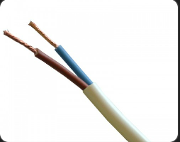
What are 2-core PVC insulated and sheathed cable used for and how are they constructed?
Use:
Used for appliances that do not require an earth connection (Class II equipment), such as table lamps or small household devices.
Construction:
Contains two stranded copper conductors, each insulated with PVC insulation, enclosed within a PVC outer sheath.
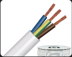
What are 3-core PVC insulated and sheathed cable used for and how are they constructed?
3-core PVC insulated and sheathed cables are used in fixed wiring installations where more than one live conductor is required, such as in two-way and intermediate lighting circuits, or for control wiring.
They are constructed with three copper conductors (typically brown, black, and grey), each insulated with PVC, and enclosed within a PVC outer sheath. A separate circuit protective conductor (earth) may also be included.
What are PILC/SWA cables used for and how are they constructed?
PILC/SWA ( Paper insulated Lead Covered Steel Wire Armoured
Use:
Used for underground power distribution and heavy-duty installations where mechanical protection and moisture resistance are required.
Construction:
Consists of copper conductors insulated with impregnated paper, enclosed in a lead sheath to prevent moisture ingress, with an additional layer of steel wire armour for mechanical protection, and an outer serving or sheath.
Key point:
A robust cable used for underground power distribution, particularly in older or industrial installations.
What are LSF cables used for and how are they constructed?
(Low Smoke and Fume)
Use:
Used in buildings where fire safety is important, such as public buildings, offices, and enclosed spaces.
Construction:
Conductors insulated with LSF materials that produce less smoke and toxic fumes when burning, with an outer LSF sheath.
Key thing to know:
Produces less smoke and fewer toxic gases during a fire, improving safety
What type of circuit normally supplies a water heater, what type of cable is used, how its protected, how its isolated and how its kept electrically safe?
A water heater circuit is normally supplied by a dedicated radial circuit from the consumer unit to an electric immersion or storage water heater. It is commonly wired using 2.5 mm² twin and earth PVC insulated and sheathed cable and protected by a 16 A fuse or MCB, depending on the heater rating. The circuit usually includes a double-pole isolating switch or timer so the heater can be safely isolated for maintenance, and proper earthing and bonding must be provided to ensure electrical safety
A domestic ring final circuit can have an unlimited number of socket outlets, provided it does not exceed?
100m2
What are the 3 methods used to wire lighting circuits?
Joint box method
Loop in method
Wiring at the switch method
How a 2 way circuit works?
A 2-way lighting circuit lets you control one light from two different switches.
Each switch has a common (COM) and two connections (L1 and L2). The two switches are linked by two wires (strappers).
When you flip either switch, it changes the path of the live wire. If the path is complete, the light is on. If the path is broken, the light is off
What is a single core PVC insulated cable used for?
Its designed for drawing into trunking and conduits. Its also suitable for surface wiring where there is little risk of mechanical damage.
What are the basics if installing PVC cables?
PVC cables should be installed so they are not damaged, avoiding sharp bends, cuts, or excessive strain, and must be properly supported using clips or fixings to prevent sagging. They should be routed in safe zones and kept away from heat, moisture, and other services where possible. Their bends shall be such that the cable or conducted does not suffer damage.
How PVC bell wire is used and how it is constructed?
PVC bell wire is a flexible, low-voltage wire made of stranded copper conductors coated in color-coded PVC insulation, typically 0.5–1 mm², used for doorbells, buzzers, intercoms, alarms, and other small-signal circuits; it can be run in conduit, trunking, or along skirting, but is not for high-power loads.
What are porcelain connectors & junction boxes?
Porcelain connectors are used to join or terminate conductors safely and provide insulation and high heat resistance, typically in high-temperature applications such as heating appliances and lighting equipment.
Junction boxes are used to contain and protect electrical connections, preventing damage, moisture ingress, and accidental contact, while allowing circuits to be connected or branched safely.
What should the CSA of the wires be for immersion heaters, cookers and electric shower circuits?
Immersion heater – 2.5 mm2
Cooker - 6 mm²
Electric shower – 10 mm²
What must my testing equipment have?
It must have a current calibration certificate.
How are SWA cables made and when is it installed?
PVC/SWA/PVC cable is made with stranded copper conductors covered by inner PVC insulation, surrounded by steel wire armour for mechanical protection, and finished with an outer PVC sheath; it is installed where mechanical strength or outdoor/underground durability is needed, such as underground power feeders, outdoor circuits, or industrial installations
What are cables using thermosettings installation used for and how are they made?
Thermosetting cables use conductors insulated with heat-resistant materials such as XLPE or EPR, along with a protective sheath. The insulation is applied by extrusion and then chemically cross-linked, which allows it to withstand higher temperatures, typically up to 90°C under normal operating conditions. These cables are used where higher temperature performance, mechanical strength, or chemical resistance is required, such as in industrial installations, switchgear, and power distribution systems.
What is a single-core PVC insulated and sheathed cable used for?
A single-core PVC insulated and sheathed cable has one conductor with PVC insulation and an outer PVC sheath, and it is used for fixed wiring in domestic, commercial, or industrial installations, such as lighting, power circuits, or connecting equipment, especially where the cable needs protection but only a single conductor is required.
What are cable joints and connections used for & when can they be used?
Cable joints and connections are used to join two cables or connect a cable to equipment when a continuous run isn’t possible or when terminating at devices. They should be used only in accessible, protected locations, with proper insulation, mechanical support, and waterproofing if needed, ensuring the joint maintains the cable’s current rating, voltage rating, and safety
What are heat resisting PVC insulated and sheathed flexible cords use and construction?
Heat-resisting PVC insulated and sheathed flexible cords consist of fine stranded copper conductors, providing flexibility, with heat-resisting PVC insulation and an outer PVC sheath. They are designed to operate at higher temperatures, typically up to around 90°C, compared to standard PVC. These cords are used for portable appliances and equipment where flexibility and moderate heat resistance are required, such as kitchen appliances, heaters, and workshop tools.
What do the national associated of professional inspections and tests (NAPIT) define a portable appliance to be?
A portable appliance is any electrical device that can be moved while connected to the supply, like kettles, drills, or heaters, and should be inspected for plugs, cables, insulation, and general safety before use.
What are the earth clamp colours for the correct environment?
Red - for dry, non corrosive atmosphere.
Blue - for corrosive or hummed conditions
Green for corrosive or humid conditions, large earth, large conductors.
Why and how terminating cable ends to crimp terminals are done?
Terminating cable ends with crimp terminals is done to create a secure, reliable connection by stripping the insulation, inserting the conductor into the terminal, and compressing it with a crimping tool
What is the acronym used to describe the four factors of a conductors resistance?
M → Material (type of conductor, e.g. copper, aluminium)
A → Area (cross-sectional area of the conductor)
L → Length (longer = higher resistance)
T → Temperature (higher = higher resistance)
What are the three cable carrying installation methods?
Method | Example |
|---|---|
A | Enclosed in conduit in insulation |
C | Clipped direct |
B | In conduit/trunking |
What are the tabulated current capacity?
Cable Size | Current Capacity |
|---|---|
1.0 mm² | ~16 A |
1.5 mm² | ~20 A |
2.5 mm² | ~27 A |
4 mm² | ~37 A |
6 mm² | ~47 A |
10 mm² | ~65 A |
If the cable is flat then think slightly less current. Only use 0.87 if the question gives 35 degrees (adjust if needed).
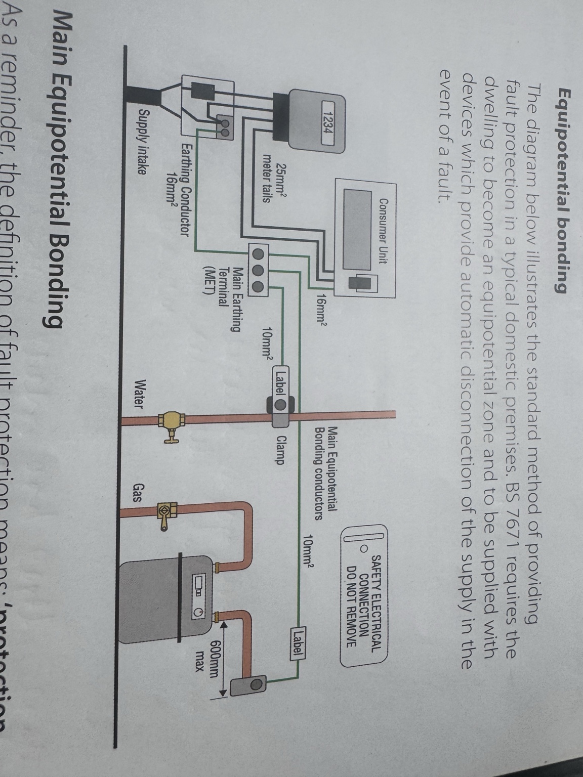
What is the MET, earthing conductor and bonding conductor?
Main earthing terminal (MET) → The central connection point for all earthing, usually located in or near the consumer unit, where the earthing conductor, circuit protective conductors (CPCs), and bonding conductors are connected.
Earthing conductor → The conductor that provides a path from the installation to earth (or the supply earth).
Bonding conductor → A protective conductor that connects metal parts (extraneous-conductive-parts) to the main earthing terminal to reduce the risk of electric shock.
Cable sizes in an installation that I must know?
Meter tails → 25 mm²
Earthing conductor → 16 mm²
Bonding → 10 mm²
What are concentric cables used for and how are they made?
Concentric cables are used in TN-C-S (PME) systems to supply electricity from the distribution network to properties. They carry a line conductor and a combined PEN (Protective Earth and Neutral) conductor, which may be split into separate neutral and earth conductors at the service position.
Co
They consist of a central copper conductor (line) surrounded by insulation, with an outer layer of concentric copper wires that act as the PEN conductor. In some cases, this outer conductor is divided into two groups to form a split concentric cable, providing separate neutral and earth conductors. The cable is enclosed within an outer sheath.
What is known as the voltage measurement from positive to negative peak?
Its known as the peak to peak value.
What are hertz and what is the equation for this?
When one cycle of emf is generated with one complete revolution of the loop over a period of one second, then we would express this as a frequency of 1 Hz. The frequency of the waveform is equal to speed of the loop’s rotation.
How can a DC motor be reversed?
The direction of rotation of a DC motor can be reversed by reversing the current in either the armature or the field winding, which changes the direction of the magnetic interaction. In practice, this is usually done by reversing the armature connections, as it is the simplest method.
How is a DC series motor constructed and what is it best suited for?
A series motor has its field winding connected in series with the armature. This gives it a very high starting torque and a variable speed characteristic. The motor is well suited for driving heavy loads, as it can produce a large turning force at startup. However, the speed increases significantly as the load decreases, which can make it dangerous if run with no load. A universal motor is a type of series motor that is designed to operate on both AC and DC supplies.
How is a shunt motor constructed and what is it best suited for?
A shunt motor has its armature and field windings connected in parallel, which produces a relatively constant magnetic field and therefore maintains an approximately constant speed. However, the speed may vary slightly with changes in load.
How is a compound motor constructed and what is it best suited for?
A compound motor combines the characteristics of both series and shunt motors. It provides high starting torque from the series winding and relatively constant speed from the shunt winding. This makes it suitable for applications where both high starting torque and stable speed are required.
Why did AC generators become the main choice?
Transformers make it easy to adjust AC to a higher or lower voltage very efficiently. This is useful, because transmitting at high voltage reduces current and power loss and allows the use of smaller cable sizes, lowering costs.
Good AC motors (and generators) are easier and cheaper to build and maintain than good DC motors.
How a Low pressure mercury lamp is constructed and how it produces visible light?
Its basically a glass tube having a filament at each end, with the tube filled with low pressure mercury vapour and a mix of additional gases such as krypton or argon. The inside of the glass tube has a phosphor coating and at each end there is a sealed set of oxide-coated electrodes, known as cathodes. In use, an ark forms causing the ionisation of the mercury gasses emitting ultra violet light.
This in turn excites the tubes phosphor coating and converts it into visible light. A choke or a transformer is used to give a quick initial charge of voltage to activate the lamp but then decreases to maintain the light.
What is colour appearance for a lamp?
This is the actual look of the lamp. The two ends of the scale are described as warm and cold. These extremes are related to temperatures: the higher the temperature, the cooler the lamp.
This is important for the overall effect, and generally warm lamps are used to give a relaxed atmosphere, while cold lamps are used wherever efficiency and business-like attitudes are a priority.
What is colour rendering for a lamp?
This describes a lamp’s ability to show colours as they truly are. This can be important depending on the building usage, such as a art gallery or a museum. The rendering of colour can also affect people’s attitude to work etc.
How production of energy in a polyphase system works (power station)
Most electricity in the UK is produced in power stations by an alternator rotates to generate electricity. In the majority of cases, by water that’s heated until it becomes high-pressure steam.
As it rotates it produces an alternating voltage (AC). The speed of rotation of the generator determines the frequency. In the UK, generators are controlled to rotate at a speed that produces 50 cycles per second
What is the national grid?
The National Grid is a network of nearly 5000 miles of overhead and underground power lines that link power stations together. This network is interconnected throughout the country.
The transmission network transports electricity from generation units to distribution companies and a small number of large industrial customers. The distribution companies then deliver electricity to the majority of customers through lower voltage networks. It is done this way so that if a problem occurs from one power station or line, power can flow from another. Electricity is transmitted around the grid, mainly via steel-cored aluminium conductors which are suspended from steel pylons
The cost of installing cables underground is excessive.
Air is a very cheap and readily available insulator.
Air also acts as a coolant for the heat being generated in the conductors.
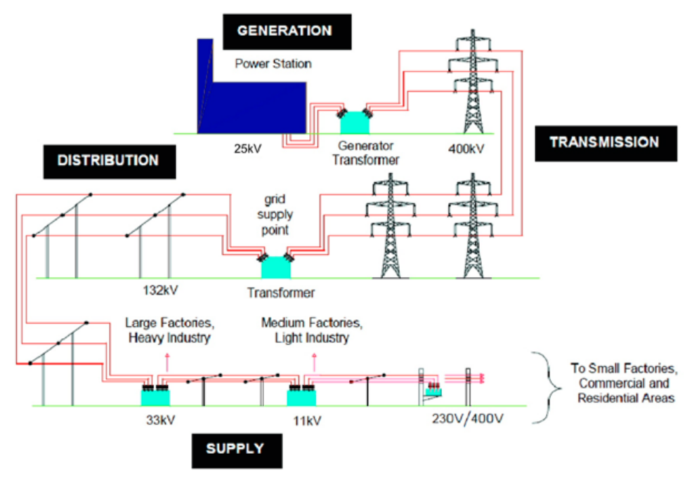
How does electricity go from national grid to small factories, commercial and residual supply areas?
Electricity is transmitted through the National Grid at 400 kV or 275 kV. It is stepped down at substations to 132 kV, then to 66 kV or 33 kV for secondary transmission. It is further reduced to 11 kV for local distribution and finally stepped down to 400 V for commercial use and 230 V for domestic consumers. At the final transformer, the secondary winding is connected in star and earthed to provide a neutral, forming a three-phase, four-wire system.
How distribution to the customer works
Once electricity leaves the local substation, it is reduced to a usable voltage and supplied to the consumer at the intake position. At this point, equipment belonging to the supply company is installed, including an energy meter to measure electricity usage and a sealed service fuse (cut-out) to protect the supply cable. Beyond this point is the consumer’s installation, which must be controlled by a main switch located as close as possible to the intake equipment and capable of isolating all live conductors. In a typical domestic installation, this is incorporated into a consumer unit, which also distributes and protects the final circuits
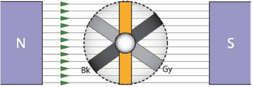
How does an AC generator work?
AC generators produce electricity using electromagnetic induction. In a three-phase generator, three stator windings are spaced 120° apart. A rotating magnetic field produced by the rotor causes a change in magnetic flux linkage in each winding, inducing an electromotive force (emf).
As the magnetic field rotates, the induced emf varies continuously. The emf is maximum when the conductor is at 90° to the magnetic field and zero when it is parallel to it. As the rotation continues through 360°, a sinusoidal (sine wave) voltage is produced.
This results in three alternating voltages of equal magnitude and frequency (50 Hz), each 120° out of phase with one another. A neutral conductor may be provided to carry unbalanced currents when the loads across the phases are not equal.
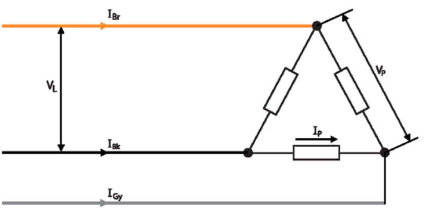
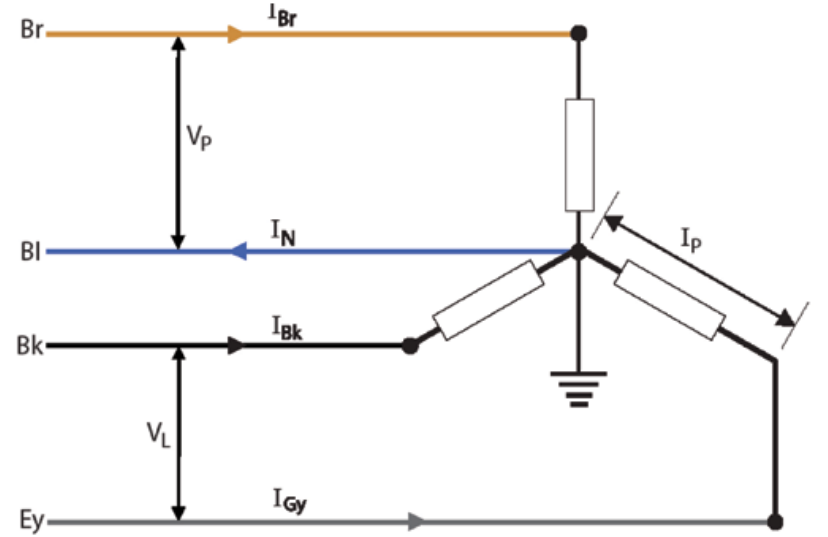
How is a delta connection and how is it designed?
In a delta connection, each phase of the load is connected between two line conductors, so the phase voltage is equal to the line voltage (VL = Vp). The line current is the phasor sum of the phase currents, and in a balanced system IL = √3 × Ip. Delta connections are used where no neutral is required.
How does a star connection work?
A star connection consists of three phases connected to a common central point called the star point, from which the neutral conductor is taken and earthed. This forms a three-phase, four-wire system and allows both balanced and unbalanced loads to be supplied. In a star connection, the phase voltage is between a line conductor and neutral, while the line voltage is higher (VL = √3 × Vp).
How a load from a three phase four wire system is balanced?
Loads in a three-phase four-wire system should be balanced so that each phase carries approximately the same current, preventing overloading and improving efficiency. This allows for appropriate cable sizing and cost-effective installation. The designer can estimate maximum demand by applying diversity to standard circuit arrangements, such as ring final circuits, lighting, and cooking appliances. Once diversity is applied, single-phase loads are distributed evenly across all three phases to achieve balance and reduce neutral current.
kV ratings for each stage of the electrical grid
400 kV and 275 kV for the super grid
132 kV for the original National Grid
66 kV and 33 kV for secondary transmission
11 kV for local sub-station distribution and industry
400 V for commercial consumer supplies
230 V for domestic consumer supplies
What is reactance (x)?
Reactance is the opposition to current flow in an AC circuit caused by inductors and capacitors, which store and release energy rather than dissipating it as heat. Inductive reactance (XL) opposes changes in current, while capacitive reactance (XC) opposes changes in voltage, and it only occurs in AC because the current is constantly changing.
What is the maximum current rating for a standard UK domestic socket outlook?
13 amps
What are fuses and how do they work?
A fuse is a safety device used to protect electrical circuits from excessive current. It consists of a thin metal wire connected in series with the circuit, which heats up as current flows through it. If the current becomes too large, the wire melts and breaks the circuit, providing overcurrent protection. This prevents overheating, reduces the risk of fire, and protects equipment from damage. Rewireable fuses can be repaired by replacing the fuse wire after operation. In plug tops, standard fuse ratings are typically 3 A, 5 A, or 13 A.
What is a DC circuit and what is an EMF?
A DC circuit works by allowing current to flow in one direction from a power source, like a battery, around a complete loop. The battery provides a voltage that pushes the current through components such as lamps or resistors, where energy is used.
EMF (electromotive force) is the voltage supplied by the source that pushes the current around the circuit.
What are series and parallel circuits?
A series circuit is a circuit where components are connected one after another in a single path. Because there is only one path, the same current flows through every component, but the voltage is shared between them. If one component fails or the circuit is broken, the whole circuit stops working.
A parallel circuit is a circuit where components are connected on separate branches across the power supply. Each branch receives the same voltage, but the current is divided between the branches. Branches with lower resistance carry more current, while branches with higher resistance carry less. If one branch breaks, the others continue to operate, which is why parallel circuits are used in homes
What are the contents of a consumer unit?
Consumer unit includes devices such as:
MCB which is the main switch or sometimes called isolator which protects cables and equipment (overload or short circuit).
RCD which protects people (earth leakage or electric shock) for additional protection in case of a earth fault.
Circuit breaker comes in different types (usually type b) and different ratings but is used for surge protection.
Internal wiring.
Bus bar used to connect the bottom of the RCD and circuit brackets.
How can I find the fuse rating?
You must find the current of a circuit. If given current, then use that directly. If given power, use power formula. If given resistance, use ohm formula.
Once the current is calculated, a fuse should be selected with a rating slightly above the operating current, typically between 1.25 and 1.5 times the current.
What are the pieces of equipment needed to safely isolate?
Multiple different types of locks
Multi hasp, if needed to apply more than one padlock.
GS38 voltage indicator device.
Proving unit
Pad lock with one key for each operative
signage
Insulated screw divers (VDE standard)
What is the correct procedure for safely isolation?
Identify means of isolation, Unplug all equipment
Obtain permission to isolate, very important!
Switch off, make sure their isn’t other sources of power such as a UPS or solar panel.
Lock off, place warning label
Secure key (in pocket)
Select an approved voltage indicator (GS38)
Test voltage indicator on a known source
Test between all live conductors
Test between all live conductors and earth
Re-test voltage indicator on a known source
What are incandescent lamps, pros and cons and things to know?
Used for
Older domestic lighting
Decorative lamps
Advantages
Instant full brightness
Simple construction
Good colour rendering
Disadvantages
Very inefficient (most energy becomes heat)
Short lifespan
Being phased out in many places
Life expectancy
~1000 hours
Efficiency
~10–15 lm/W
Current / fuse
Depends on wattage (e.g., 60 W lamp ≈ 0.26 A at 230 V)
Usually protected by lighting circuit fuse/MCB (6 A)
Key things to know
Light produced by heating a tungsten filament
Very high heat output
What are halogen lamps, pros and cons, and things to know?
Used for
Spotlights
Floodlights
Downlights
Vehicle headlights
Advantages
Brighter than incandescent
Better efficiency
Longer life
Small compact lamp
Disadvantages
Runs very hot
Still inefficient compared with LED
Can be a burn hazard
Life expectancy
~2000–4000 hours
Efficiency
~15–25 lm/W
Current / fuse
Depends on wattage (e.g., 50 W ≈ 0.22 A at 230 V)
Protected by normal lighting circuit protection
Key things to know
Uses halogen gas (iodine/bromine)
Tungsten redeposits on filament (halogen cycle)
What are fluorescent lamps, pros and cons and things to know about them?
Used for
Offices
Schools
Warehouses
Garages
Advantages
Much more efficient than incandescent
Long lifespan
Good for large areas
Disadvantages
Needs ballast and starter
Slight warm-up time
Contains mercury
Life expectancy
~10,000–20,000 hours
Efficiency
~60–100 lm/W
Current / fuse
Depends on lamp rating (e.g., 36 W tube ≈ 0.16 A at 230 V)
Protected by normal lighting circuit protection
Key things to know
Works by electric discharge through mercury vapour
Ballast controls current
What are LED lamps, pros and cons and things to know?
Used for
Most modern lighting
Homes
Street lighting
Commercial buildings
Advantages
Very energy efficient
Very long lifespan
Low heat
Instant start
Disadvantages
Higher upfront cost
Requires electronic driver
Life expectancy
~25,000–50,000 hours
Efficiency
~80–150+ lm/W
Current / fuse
Very low current (e.g., 10 W ≈ 0.043 A at 230 V)
Protected by lighting circuit protection
Key things to know
Uses semiconductor diode
Converts electrical energy directly to light
What is a control gear, semi resonant circuit and a glow type starter?
Control gear: Electrical components used in discharge lighting to start the lamp and control the current during operation, such as a ballast and starter.
Glow-type starter: A small device used in fluorescent lamps that briefly closes to heat the lamp filaments and then opens to create a voltage surge from the ballast, which starts the lamp.
Semi-resonant circuit: A starting circuit used in some discharge lamps where inductors and capacitors create a resonant effect that produces a higher starting voltage to ignite the lamp and help control the current once it is operating.
What are the requirements of a non fused spur?
Taken from a ring final circuit.
No additional fuse protection at the spur.
Can supply one single socket outlet OR one fixed appliance only.
Must be connected from a socket outlet on the ring or from a junction box on the ring.
Usually wired in 2.5 mm² twin and earth cable.
The ring circuit is normally protected by a 32 A fuse or MCB
A domestic ring final circuit can have an unlimited number of socket outlets, provided it does not exceed?
100m2
What are the 3 methods used to wire lighting circuits?
Joint box method
Loop in method
Wiring at the switch method
How a 2 way circuit works?
A 2-way lighting circuit lets you control one light from two different switches.
Each switch has a common (COM) and two connections (L1 and L2). The two switches are linked by two wires (strappers).
When you flip either switch, it changes the path of the live wire. If the path is complete, the light is on. If the path is broken, the light is off
How does a battery in a circuit work?
A battery works in a circuit by creating a voltage difference between its positive and negative terminals, which pushes electrons through the circuit, producing an electric current that powers devices, while chemical reactions inside the battery maintain the flow until the energy is used up.
What must my testing equipment have?
It must have a current calibration certificate.
What may a non- fused spur attached to a domestic ring final circuit supply?
One single or one double socket outlet.
What are class 0, 1, 2, 3 &hand held equipment or appliances?
Class 0: Basic insulation only, no earth; relies solely on insulation for protection (rare, unsafe by modern standards).
Class 1: Basic insulation with earth connection for safety.
Class 2: Double or reinforced insulation, no earth required.
Class 3: Powered by SELV; extra-low voltage, no earth needed.
Hand-held equipment/appliances: Portable devices designed to be held during use, requiring careful insulation, sometimes double-insulated (Class 2), and protected against electric shock
What do the national associated of professional inspections and tests (NAPIT) define a portable appliance to be?
A portable appliance is any electrical device that can be moved while connected to the supply, like kettles, drills, or heaters, and should be inspected for plugs, cables, insulation, and general safety before use.
what are fixed equipment appliances, stationary equipment, or appliances, movable equipment?
Fixed equipment/appliances: Permanently installed, e.g., boilers, cookers.
Stationary equipment/appliances: Not designed to be moved often, e.g., large motors or factory machines.
Movable equipment/appliances: Can be moved but not necessarily hand-held, e.g., trolley-mounted tools.
What is a IP rating guide?
An IP rating (Ingress Protection) indicates the level of protection an enclosure provides against solid objects and water, with the first digit for solids/dust and the second digit for liquids.
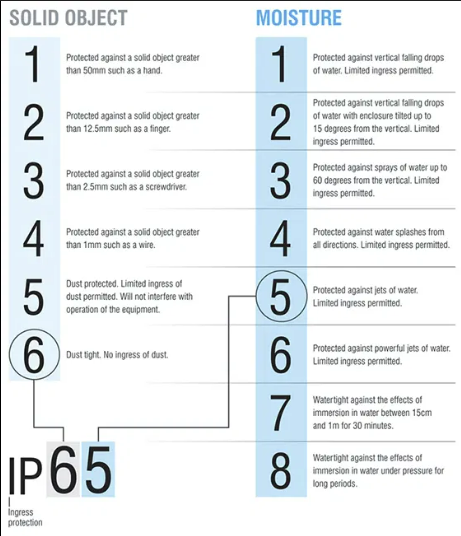
What are the IPX rating, diameters, types of splashes and what type of electrical appliances for zone 0, 1, 2 and 3?
Zone 0 = underwater → IPX7
inside the bath or shower tray.
SELV equipment rated for Zone 0
Maximum 12 V AC or 30 V DC
Zone 1 = heavy splashes → IPX4
Above the bath or shower tray
Up to 2.25 m vertically from the floor
Zone 2 = light splashes → IPX4
0.6 m horizontally outside Zone 1
Still up to 2.25 m high
Zone 3 = outside bathroom area → no special IP
minimum distance you can have a socket outlet from an edge of a bath or a shower is 2.5m
What is the prescribes tests order?
Continuity of protective conductors, including bonding conductors
Ring final circuits - continuity of conductors
Insulation resistance
Polarity (Dead test)
Earth electrode resistance (If required)
Polarity (Live test)
Earth electrode resistance (If required)
Earth fault loop impedance Ze
Prospective fault current
Earth fault current impedance Zs
Testing of RCD
Functional testing
What is an insulation resistance test, is it a live or dead test, what test equipment is used and how is it tested?
The insulation resistance test is a live test carried out to verify that the insulation of a circuit is in good condition and prevents leakage current between live conductors and earth (earth loop faults). After safely isolating the supply and removing sensitive equipment (such as electronic devices, dimmers, or surge protectors), all switches are turned on and loads removed to ensure the full circuit is tested. Using an insulation resistance tester (Megger), a DC test voltage (typically 500 V for most 230 V circuits) is applied between line and neutral, line and earth, and neutral and earth. The resistance readings should be high; according to regulations, a minimum of 1 MΩ is acceptable, though values are usually much higher in a sound installation. Low readings may indicate damaged insulation, moisture ingress, or wiring faults. This test ensures the circuit is safe, reduces the risk of electric shock and fire, and confirms the integrity of the insulation system.
In a brand new installation, sometimes all circuits may be tested together. However if the reading shows less than 2MΩ, then each circuit must be tested for a minimum of 1Ω.
What are the test voltage and minimum insulation resistance values for different circuit voltages?
SELV & PELV - 250 V test voltage - Min IR value 0.5MΩ
LV up to 500V - 500 V test voltage - Min IR value 1.MΩ (normal installation)
500 V to 1000 V - 1000V test voltage - Min IR value 1MΩ
What is thepolarity test, is it a live or dead test, what test equipment is used and how is it tested?
Dead polarity test:
With the supply safely isolated, the line conductor and CPC are temporarily linked at the distribution board. Using a continuity tester, a resistance measurement is taken between line and earth at each outlet. A low resistance reading confirms correct polarity, proving that the line conductor is connected to the correct terminals (such as switches or centre contacts) and not incorrectly connected to neutral.
Live polarity test:
A live polarity test confirms that the line, neutral and earth conductors are correctly connected when the circuit is energised. Using a two-pole voltage tester at each point of use (socket, switches), approximately 230 V should be measured between line and neutral and between line and earth, with little or no voltage between neutral and earth. This confirms correct polarity and safe operation.
Protective devices:
Protective devices such as fuses and MCBs must be connected in the line conductor so they can disconnect the supply during a fault and remove dangerous voltage.
What are the expected measurements results when conducting polarity on single and three phase supplies?
Single phase:
Earth - Line = 230V
Earth - neutral = 0V
Neutral - Line = 230V
The key test for confirming supply polarity is Line to Earth.
Three phase:
Earth - L1 = 230V
Earth - L2 = 230V
Earth - L3 = 230V
Earth - Neutral = 0V
Neutral - L1 = 230V
Neutral - L2 = 230V
Neutral - L3 = 230V
L1 - L2 = 400V
L1 - L3 = 400V
L2 - L3 = 400V
What are the different types of spurs, what’s its protection, what it can supply, cable it uses and what’s its disconnection time?
Spur Type | Protection | What it Can Supply | Cable | Disconnection Time |
|---|---|---|---|---|
Unfused Spur | Protected by 32A Type B MCB of ring circuit | One single socket OR one double socket | 2.5 mm² T&E | 0.4 s |
Fused Spur (FCU) | 13A fuse inside FCU | Multiple sockets or fixed appliances | 2.5 mm² T&E | 0.4 s |
What is the purpose of voltage drop and what is the maximum voltage drop for Lighting and power circuits?
The purpose of voltage drop is to verify that the voltage remains within allowable limits.
Lighting : Not to exceed 3% of a nominal voltage (6.9)
Power : Not to exceed 5% of the nominal voltage (11.5)
What is the simple memory trick to find the cable resistance at a specific temperature?
20 °C → 1.00 (normal reference)
Every 5 °C colder → about +0.02
Every 5 °C hotter → about −0.02
What are SELV & PELV circuits?
SELV (Separated Extra-Low Voltage) circuits are electrical systems where the voltage is low enough (typically ≤50 V AC or ≤120 V DC) and electrically separated from mains supply to prevent electric shock, often used in doorbells, safety lighting, or control circuits.
PELV (Protective Extra-Low Voltage) circuits also operate at extra-low voltage but may have a connection to earth for safety; they are used where low voltage is needed but earth reference is acceptable, such as industrial control panels or lighting systems.
How a thermal starter circuit works?
A thermal starter circuit protects a motor from overload by passing current through a bimetallic strip that bends when overheated, causing the circuit to trip and stop the motor. The device must then be reset once it has cooled.
What are voltage bands and what are the three bands?
Voltage bands are used to classify electrical voltages into ranges for safety and regulation purposes.
Band I – Extra Low Voltage (ELV)
Includes SELV and PELV
< 50 V AC
< 120 V DC
Band II – Low Voltage (LV)
Includes typical supplies such as:
230 V (domestic)
400 V (three-phase)
50 – 1000 V AC
120 – 1500 V DC
Band III – High Voltage (HV)
> 1000 V AC
What is a relay and what are they used for?
A relay is an electromechanical switch that uses an electromagnet to operate one or more sets of contacts, allowing a circuit to be opened or closed.
Relays are used to:
Control a high-current circuit using a low-current signal (e.g. lighting in a theatre or leisure centre controlled from a low-current switch)
Control a high-voltage circuit using a low-voltage signal
Control mains-powered equipment from an extra-low voltage (ELV) control circuit
They also provide electrical isolation between the control circuit and the load circuit.
What are the things to consider when choosing the correct relay?
Contact arrangement - The contact geometry indicates how many poles there are, and how they open and close.
Coil voltage – this indicates how much voltage (e.g. 230 V, 24 V ) and what kind (AC or DC) must be applied to energise the coil. Always make sure that the coil voltage matches the supply being fed into it.
Contact ratings – this indicates how heavy a load the relay can run
What are the most common electrical faults in circuits, what they are normally due to and what risk they present?
1. Earth fault
Current leaks from a live conductor to earth
Usually caused by damaged insulation or faulty equipment
Risk of electric shock
Protected by: RCDs / fuses / MCBs (indirectly)
2. Short circuit
Fault between live conductors (very high current):
Line–neutral (single-phase)
Line–line (three-phase)
Causes very high current instantly
Protected by: MCBs (magnetic trip) / fuses
3. Overload
Too much current drawn over time in normal path (not a fault to earth)
Caused by too many appliances or oversized load
Protected by: MCBs (thermal trip) / fuses
What are the two types of tripping for an MCB?
Thermal tripping – the load passes through a small heater coil wrapped around a bi-metal strip. When the current is too high, the strip rises and trips the latch. This is used for overloads as some systems will only feature small overloads, where a sudden shutdown of power may cause more damage. Thermal tripping is more advisable as it relies on a build up of heat. magnetic can trip almost immediately.
Magnetic tripping – a magnetic field is set up around a flexible strip. When the current is too high the latch is operated This is for short circuits as it operates instantaneously.
How the rating of a protective device (In) should be chosen?
Once you know the design current (Ib) of a circuit, the next step is to choose a suitable protective device with the correct current rating (In).
The Wiring Regulations state that the rating of the protective device (In) must be equal to or greater than the design current (Ib). This means the device can carry the normal current of the circuit without tripping unnecessarily.
The final choice of protective device will depend on the type of circuit, the equipment being used, and the required disconnection times.