Computer Networking Fundamentals - Final Exam
1/229
Earn XP
Description and Tags
Final exam notes for COT4700
Name | Mastery | Learn | Test | Matching | Spaced | Call with Kai | Chat |
|---|
No analytics yet
Send a link to your students to track their progress
230 Terms
Border Gateway Protocol
The glue that holds the internet together. Arguably the most important of all of the Internet protocols.
Allows subnet to advertise its existence and the destinations it can reach, to rest of internet.
What BGP Provides for Autonomous Systems
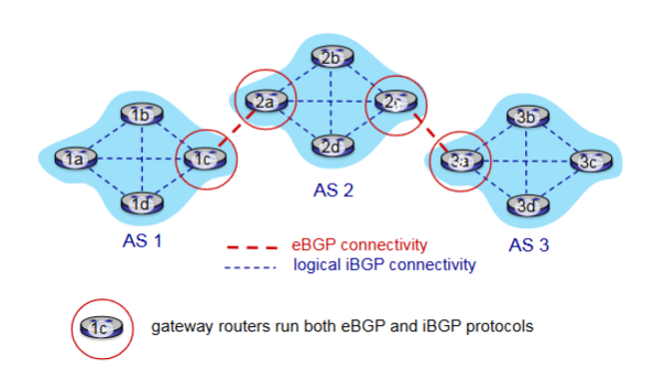
eBGP & iBGP
Determine good routes to other networks based on reachability information and policy
external BGP (eBGP)
obtain subnet reachability information from neighboring Autonomous Systems.
internal BGP (iBGP)
propagate reachability information to all Autonomous Systems routers.
eBGP & iBGP Connections
BGP Session
Two BGP routers (“peers”) exchange BGP messages over semi-permanent TCP connection.
BGP Advertised Route
Prefix - destination being advertised
Two Important Attributes
AS-PATH
NEXT-HOP
AS-PATH
List of the autonomous systems through which prefix advertisement has passed
NEXT-HOP
Indicates specific internal-AS router to next-hop AS. Includes the IP address of the router interface that begins the AS-PATH
Policy-based Routing
Gateway receiving route advertisement uses import policy to accept/decline path
Determines whether to advertise path to other neighboring ASes
BGP Messages
Messages in BGP exchanged between peers over TCP connection
Examples: OPEN, UPDATE, KEEPALIVE, NOTIFICATION
BGP OPEN
Opens TCP Connection to remote BGP peer and authenticates sending BGP peer
BGP UPDATE
Advertises new path or withdraws old
BGP KEEPALIVE
Keeps connection alive in absence of UPDATES; also ACKs OPEN request
BGP NOTIFICATION
Reports errors in previous msg; also used to close connection
Difference of Intra-AS & Inter-AS Routing
Policy
Inter-AS: admin wants control over how its traffic routed, who routes through its network
Intra-AS: single admin, so policy less of an issue
Scale
Hierarchical routing saves table size, reduced update traffic
Performance
Inter-AS: policy dominates over performance
Intra-AS: can focus on performance
Hot Potato Routing
Simplest BGP Routing Algorithm
The route chosen (from all possible routes) is that route with the least cost to the NEXT-HOP router beginning that route. (Least intra-domain cost)
The idea is to get packets out of its AS as quickly as possible without worrying about the cost of the remaining portions of the path outside of its AS to the destination
Packets are the H__ P_____ that you want to pass as quickly as possible
Hot Potato Routing as a Selfish Algorithm
Tries to reduce the cost in its own autonomous system while ignoring the other components of the end-to-end costs outside its AS
Route Selection
Router may learn about more than one route to destination AS based on:
Local preference
Shortest AS-PATH
Closest NEXT-HOP: Hot potato routing
Additional Criteria
Local Preference
Could have been set by the router or could have been learned from another router in the same AS. The value of the local preference attribute is a policy decision that is left entirely up to the AS’s network administrator.
Internet Control Message Protocol (ICMP)
Used by hosts and routers to communicate network-level information to each other.
Common Uses:
Error reporting - unreachable host
Echo Request/Reply (Ping)
Sits just above IP; Carried in IP datagrams
ICMP Message
Type and Code Field plus first 8 bytes of IP datagram causing error
Smurf Attack
Amplification attack
‘Ping’ sent to the broadcast address in a subnet (255.255.255.255) or network (192.168.1.255)
All hosts receiving this message would automatically respond and clog the network which only talk one message to initiate.
Link Layer Responsibility
Transfer datagrams from one node to a physically adjacent node over a link
Link
communication channel that connect adjacent nodes along communication path
Examples:
Wired
Wireless
LANs
Link Layer Services
Framing, Link Acess
Reliable Delivery Between Adjacent Nodes
Flow Control
Error Detection
Error Correction
Half-Duplex / Full-Duplex
Framing
Encapsulation for datagram into a frame and adding the header
Channel Access (Things that can directly access each other / same wifi)
MAC address to specify source and destination
Network Interface Card
Location of the link layer implementation (In each and every host)
Attached to system buses
Software, Hardware, Firmware Combo
Why Error Detection in Link Layer?
Errors are most likely to occur here, and we want to catch them as fast as humanly possible.
What’s Special About the Link Layer Error Detection?
Because it occurs on software and hardware we need to consider both. The extra support is specially dedicated hardware (and firmware) to keep it protected.
Single Bit Parity
Detect single bit errors
Even Parity
(Sinlge-bit) Set parity bit so there an even number of 1’s
Two-dimensional bit parity
Detect and correct single bit errors
Cyclic Redundancy Check (CRC)
More powerful error-detection coding
Goal: Choose r CRC bits, R, such that <D,R> is exactly divisible by G (mod 2)
Widely used
Detects all burst errors in r + 1.
Two Types of Links
Point to Point
Broadcast
Broadcast Link
A network link where multiple nodes can send and receive data over a shared medium.
Shared wire/medium
Old-fashioned Ethernet
802.11 wireless LAN, 4G 4G Satellite
Point-to-Point Link
A direct communication link between two nodes with no other devices sharing the link.
Multiple Access Protocol
Distributed algorithm that determines how nodes share a channel.
Communication about channel sharing must use channel itself.
MAC Classes
Channel Partitioning
Random Access
“Taking Turns”
Channel Partitioning
Divide the channel into smaller pieces
Allocate piece to node for exclusive use
Note:
Share at high load, inefficient at low load (delays, I/N bandwidth allocated)
Random Access
Channel is not divided, there are collisions and then we need to ‘recover’ from collisions
Notes:
Efficient at low load
High collisions with high load
“Taking Turns”
Nodes take turns, length of turn depends on length of what the node wants to send
Notes:
Looks for best of both worlds!
Time Division Multiple Access (TDMA)
Access to channel in rounds
Each station gets fixed amount of time
Unused slots go idle
Frequency Division Multiple Access (FDMA)
Channel spectrum divided into frequency bands
Each station gets assigned a band
Unused transmission time goes idle
Random Access Protocols
Can access channel when needed
Need to know how to detect and recover from collisions
Examples:
ALOHA, Slotted ALOHA
CSMA, CSMA/CD, CSMA/CA
Slotted ALOHA
Random Access Protocol where all nodes are given the ability to transmit in a fixed slot
If no collision, the node can send the frame.
If collision, node retransmits in each subsequent slot with a probability p until it succeeds
Pros:
Single active node can continuously transmit at full channel rate
High decentralized
Simple
Cons:
Collisions / Wastes / Idle Slots
Nodes detect collision in less time to transmit
Clock synchronization
Randomized because it keeps things fair.
~ 37% Efficient
Pure ALOHA
Simple Random Access Protocol with no synchronization.
When frame arrives, it transmits immediately
Collision probability increases
~ 18% Efficient
Carrier Sense Multiple Access (CSMA)
Listen before trasnmit
If Channel Idle: Transmit the entire frame
If Channel Busy: Defer
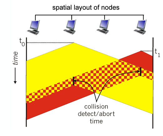
CSMA Collision
Entire packet transmission gets wasted, two nodes may not hear each other’s transmission.
CSMA/CD
All principles of CSMA with reduced amount of time wasted in collisions. (Transmission aborted upon detection)
Steps:
NIC gets datagram and creates frame
Sense channel
Idle - start transmission
Busy - Wait
If NIC transmits whole frame, done!
If another transmission detected abort, send jam signal
After aborting binary backoff
Efficiency: 1 / 1 + (5tprop/ttrans)
Efficiency goes to one as tpop goes to 0 and ttrans goes to infinity
Better than ALOHA
Binary Exponential Backoff
When transmitting a frame that has already experienced n
collisions, a node chooses the value of K at random from {0,1,2, . . . . 2n-1}. Thus, the more collisions experienced by a frame, the larger the interval from which K is chosen.
Polling
Master node ‘invites’ other nodes to transmit in turn
Concerns:
Polling overhead
Latency
Single Point of Failure at the master node
Token Passing
Control token passed from one node to the next sequentially
Concern:
Token overhead
Latency
Single point of Failure at the token node
Data Over Cable Service Interface Specification (DOCSIS)
FDM over upstream, downstream frequency channels
TDM Upstream - some slots assigned, some contention
Downstream MAP frame
Request for upstream slots
MAC Address
Local address to get frame from one interface to another physically connected interface
Burned in NOC ROM
Unique
‘Social Security Number’
Portabillity
MAC address can move interface from one LAN to another
(IP IS NOT PORTABLE IT IS SUBNET DEPENDENT)
How to Determine MAC Address knowing IP?
Address Resolution Protocol
Ethernet
‘Dominant’ wired LAN technology
First widely used
Simple / Cheap
Connectionless (no handshaking)
Unreliable (no ACKs or NAKs / no data recovery protocol either)
MAC Protocol - CSMA/CD + Binary Backoff
Bus Ethernet
All nodes in the same collision domain
(Can collide, 90s)

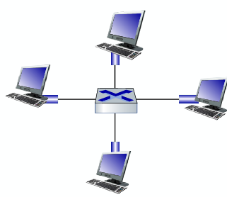
Switched Ethernet
Prevails today
Switch in center
Each ‘spoke’ runs a Ethernet protocol (no collisions)
Active Role - Store and forward
CSMA/CD
Transparent - Hosts are unaware
Plug and Play
Ethernet Frame
Encapsulates IP datagram when using ethernet
Structure:
Preamble
Addresses
Type
CRC
Preamble - Ethernet Frame
Synchronize receiver, sender clock rates
Notifier saying transmission is starting
Type - Ethernet Frame
Indicates higher layer protocol
Used for demultiplex
CRC - Ethernet Frame
Cyclic redundancy check at receiver
Frame dropped if detected
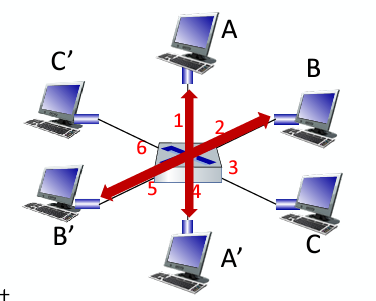
Multiple Simultaneous Transmissions
In switching, hosts have dedicated direct connections to switch where packets are buffered (received without issue). Ethernet protocol on each incoming link means there’s no collisions and its full duplex. Each link is its own collision domain.
Switching Occurs: A-A’ and B-B’ can transmit at the same time no issue, but A-A’ and C-A’ can’t. S
Switch Table
How switches know neighboring switches are reachable
Similar to routing table but has MAC addresses
Self-Learning
How entries are created in a switch table
Switch learns which can be reach through which interfaces
When a frame gets received, the switch will ‘learn’ the location of the sender and record it in the table
Steps:
Record incoming link
Index table using destination address
If entry found, filter and send; if not, flood.
Virtual Local Area Network (VLAN)
A logical grouping of devices on separate physical networks that behave as if they are on the same network.
post-based VLAN
Switch ports grouped so that a single physical switch operates as multiple virtual switches
Traffic Isolation
Dynamic Membership
Forwarding Between VLANS
Traffic Isolation
Frames to/from ports 1-8 can only reach ports 1-8, can also define VLAN based on MAC addresses of endpoints, rather than switch port
Dynamic Membership
Ports can be dynamically assigned among VLANs
Trunk Port
Carries frames between VLANS defined over multiple physical switches
Frames forwarded within VLAN between switches can’t be vanilla 802.1 frames (must carry VLAN ID info)
802.1 q protocol adds/removes additional header fields for frames forwarded between T___ P____
Multiprotocol Label Switching (MPLS)
Protocol of high-speed IP forwarding among network of MPLS-capable routers, using fixed length label (not shortest prefix)
Faster lookup using fixed length identifier
borrowing ideas from Virtual Circuit approach
IP datagram keeps address
MPLS Capable Router
Label-switched router
Forward packets based only on label values
Flexibility in Decisions:
Re-route on failures
Use destination and source addresses to route flows to the same address differently (traffic engineering)
IP Routing
Path to destination determined by destination address alone
MPLS Routing
Path to destination can be based on source and destination
Fast Reroute
Fast Reroute
Precompute backup routes in case of link failure
MPLS Signaling
Entry MPLS router uses RSVP-TE Signaling protocol
Wireless Hosts
Laptops, smartphones IoT
May be stationary or mobile
Wireless does not always mean mobility
Base Station
Connected to wired network
Cell towers, 802.11 access points
Responsible for sending packets between wired network and wireless hosts in its ‘area’
Wireless Link
Typically used to connect mobiles to base station, also used as backbone link
Multiple access protocol coordinates link access
Various transmission rates and distances and frequency bands
Infrastructure Mode
Base station connects mobiles into wired network
Handoff
Handoff
Mobile changes base station providing connection into wired network
Ad Hoc Mode
No base stations
Nodes can only transmit to other nodes within link coverage
Nodes organize themselves into a network: route among themselves
Mesh Net
Multiple hops with an infrastructure means hosts have to relay through several wireless nodes to connect to larger Internet
MANET, VANET
Multiple hops and no infra. means no base station, no connection to larger internet. May have to relay to reach other a given wireless node:
Wireless Link Characteristics
Decreased signal strength
Interference from other sources
Multipath propagation
Makes communication with more difficult because these all effect the BER (Bit Error Rate)
Multipath Propagation
Radio signals reflects off objects ground, arriving at destination at slightly different times
Signal to Noise Ratio
Larger SNR, easier to extract a signal from noise (good!)
SNR versus BER Tradeoffs
Physical Layer:
Increase Power → Increase SNR → Decrease BER
SNR:
Choose physical layer that meets BER requirement, giving highest throughput
Can change with mobility
Hidden Terminal Problem
A problem where two devices that are out of each other’s range attempt to communicate with a shared receiver, unaware of each other’s transmissions, causing potential interference and collisions at the receiver.
Signal Attenuation
The reduction of signal strength due to physical factors such as distance, interference, or obstacles. Spacing can result in the hidden terminal problem and degrade communication quality, especially in environments with moving objects.
Code Division Multiple Access (CDMA)
Unique ‘code’ assigned to each user, all users share same frequency but each user has own chipping sequence to encode data. Allows users to coexist and transmit simultaneously with minimal interference
CDMA Encoding
Inner Product: (OG Data) x (Chipping Sequence)
CDMA Decoding
Summed inner product: (encoded data) x (chipping sequence)
802.11 LAN Architecture
Wireless host communicates with base station
Basic Service Set
Uses CSMA/CA
Basic Service Set
Contains:
Wireless hosts
Access Point: Base Station
Ad Hoc Mode: Hosts Only
Passive Scanning
Beacon frames sent from AP’s
Association Request frame sent: H1 to selected AP
Association Response frame sent from selected AP to H1
Active Scanning
Probe Request frame broadcast from H1
Probe Response frames sent from APs
Association Request frame sent: H1 to selected AP
Association Response frame sent from selected AP to H1
CSMA/CA
Sender will check if idle, if so, send entire frame.
If busy, start random backoff time and then try again when expires, if still busy increase random backoff time
Receiver will return an ACK if frame is received
Sender will use DIFS and then send RTS and it is followed by a SIFS and CTS from the receiver