Friis Transformation and Radiation from Dipole
 Call Kai
 Learn
Learn Practice Test
 Spaced Repetition
 Match
Match Flashcards
 Knowt Play
1/11

Earn XP
Description and Tags
Week 3
Name | Mastery | Learn | Test | Matching | Spaced | Call with Kai | Chat |
|---|
No analytics yet
Send a link to your students to track their progress
12 Terms
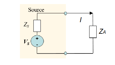
Equivalent Circuit of Antenna
ZA = RA + j XA
RA = RR + RL
RR - Radiation resistance
RL - Loss resistance
XA - Antenna reactance
Radiation Efficiency
𝜂r = power radiated / (power radiated + power lost) = RR / (RR + RL)
Power dissipated (as heat) by antenna
PA = ½ * |𝐼|2 * (𝑅𝐿+𝑅𝑅)
Reflection coefficient
Γ = (𝑍𝐴 − 𝑍𝑂 ) / (𝑍𝐴 + 𝑍𝑂)
where 𝑍𝑂 is the characteristic impedance of transmission line
when 𝑍𝐴 = 𝑍𝑂 → Γ = 0 = perfect match
VSWR
VSWR = Voltage Standing Wave Ratio = (1 + | Γ |) / (1 − | Γ |)
How well an antenna is matched or how much power it will accept from a source
VSWR of 1 indicates a perfect match
Impedance of Free Space
377
Antenna Effective Area
A measure of the ability of an antenna to capture energy
Ae = Power delivered to load / Incident power density = 𝐺𝜆2 / 4𝜋
Aperture Efficiency
𝜂Ae = effective area / physical area
Antenna Bandwidth
Band of frequencies within which antenna performance characteristics are acceptable
Characteristics:
Input impedance
Beamwidth
Gain
Sidelobes
VSWR
Axial ratio
Antenna Effective Collecting Area
The effective absorption area (Ae), presented by an antenna, gives an indication of the power collected/absorbed (PR) as in response to an incident plane wave.
PR = PAAe
Dipole Antennas
Common antenna at low frequencies < 1GHz
A linear conductor driven at its centre
Simplest dipole to analyse is a short (Herzian) dipole
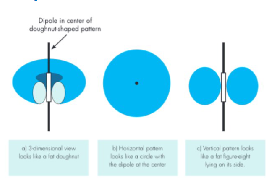
Dipole Antennas Pattern