Chapter 15 - Sequencers
1/74
There's no tags or description
Looks like no tags are added yet.
Name | Mastery | Learn | Test | Matching | Spaced | Call with Kai |
|---|
No analytics yet
Send a link to your students to track their progress
75 Terms
1. You can use register N7:0 as a control register in a sequencer output (SQO) instruction. T/F
F
2. The normally open contact R6:0/DN will close whenever the sequencer output (SQO) instruction is enabled. T/F
F
3. The normally open contact R6:0/FD will close whenever the sequencer compare (SQC) instruction is enabled. T/F
F
4. File B3 may be used to hold the sequencer output (SQO) instruction’s patterns. T/F
T
5. The length parameter specifies the number of words in the sequencer file. T/F
F
6. You can step two or more sequencer instructions simultaneously. T/F
T
7. You must use the reset (RES) instruction to reset the SQO instruction’s position to zero. T/F
T
8. The .LEN and .POS can hold numbers up to 256 since an SQO can have up to 256 steps. T/F
T
9. There are 255 sixteen-bit words in file B3. T/F
F
10. There are 255 sixteen-bit words in file B10. T/F
F
11. The ______________________________ instruction transfers data from the sequencer source file to the
output destination module.
SQO
12. The ______________________________ instruction is used to control several outputs with multiple step
patterns.
sequencer
13. PLC manufacturers use the ______________________________ instruction instead of the sequencer
instruction.
table-to-reg/file-to-word
14. The normally open ______________________________ input must be closed to energize the sequencer
instruction.
enable
15. A low-to-high pulse on the ______________________________ input causes the sequencer to advance to the
next output pattern.
step
16. When the normally open ______________________________ input is closed, the sequencer instruction
resets to the first output pattern.
reset
17. The number of ______________________________ indicates the number of data patterns the sequencer
instruction must step through.
steps
18. The ______________________________ register holds the first data pattern.
starting
19. The ______________________________ register points to the step that the instruction is on.
step pointer
20. The ______________________________ register is an output group register that indicates the output
terminals on which data is placed.
destination
21. The ______________________________ parameter in the sequencer block holds the total number of steps
that must be completed before the sequencer done status bit (R6:0/DN) coil is energized.
sequencer length
22. The ______________________________ parameter indicates the step that is desired to start the sequencer
instruction.
sequencer position
23. The ______________________________ instruction reads input data from an input module or register and
then compares the input data to the step patterns in a bit data file (B3 or B10) or integer data file (N7).
SQC
24. The ______________________________ instruction is used to read the PLC input module and store the input
data in a file.
SQL
25. The number of sequencer steps can be increased by connecting two sequencers in series, which is called
______________________________ sequencers.
cascading
26. The number of outputs that are controlled by the sequencer system can be increased by connecting sequencers
in ______________________________.
parallel
27. Name the three types of sequencer instructions of an Allen-Bradley SLC 500 series PLC.
SQC,SQL,SQO
28. Name the control registers used by sequencer functions SQO, SQL, and SQC.
R6:0, R6:255,
29. How do you reset a sequencer function?
RES
30. Name the data files that can be used for the source in a sequencer output (SQO) instruction.
B3, B10 and N7
1. The sequencer instruction is also referred to as the ____ instruction.
A. data transfer
B. drum sequencer
C. register to table
D. All of the above.
B
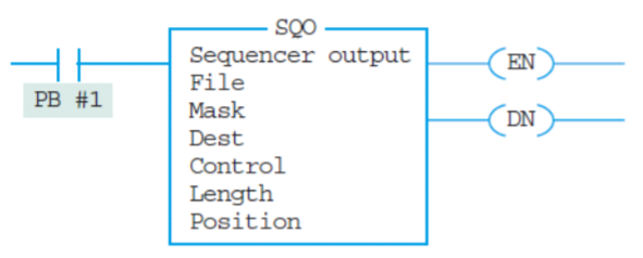
2. In the following SQO instruction block, which parameter holds the starting address?
A. File
B. Source
C. Position
D. Mask
C
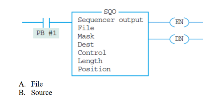
3. In the following SQO instruction block, which parameter is used to hide some of the bit patterns?
A. File
B. Source
C. Position
D. Mask
D
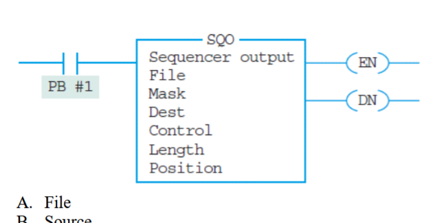
4. In the following SQO instruction block, which parameter holds the address of the output port?
A. File
B. Source
C. Position
D. Destination
D
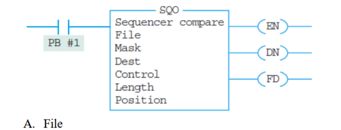
5. In the following SQC instruction block, which parameter holds the address of the input port?
A. File
B. Source
C. Position
D. Destination
B
6. Which status bit indicates whether the data on the input port matches the data stored in the sequencer data
file?
A. DN
B. FD
C. EN
D. ER
B
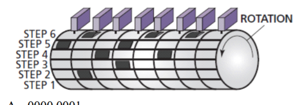
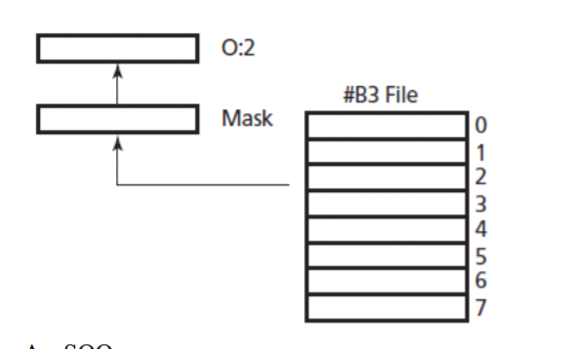
7. In the following drum sequencer, the bit pattern for Step 5 is ____.
A. 0000 0001
B. 0100 0000
C. 1001 0000
D. 0100 1010
C
8. In PLC applications where the sequencer needs to control more than 16 ports, the sequencers are connected
____.
A. simultaneously
B. in series
C. in parallel
D. in a cascading arrangement
C
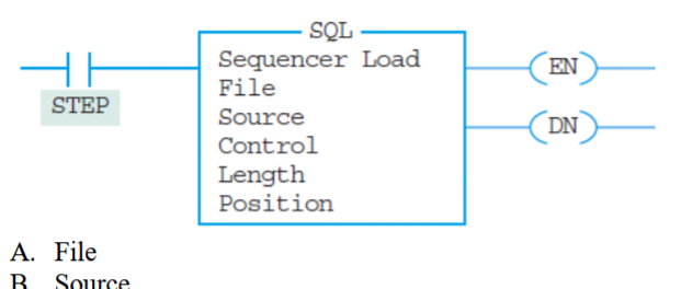
9. In the following SQL instruction block, which parameter holds the data table?
A. File
B. Source
C. Position
D. Length
A
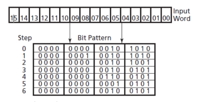
10. The following figure displays the operation of the ____.
A. SQO instruction
B. SQL instruction
C. SQC instruction
D. All of the above.
B
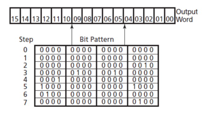
11. For the SQO instruction’s operation in the following image, which outputs are energized in Step 5?
A. 0:2/0 and 0:2/3
B. 0:2/15 and 0:2/3
C. 0:2/16 and 0:2/4
D. 0:2/15 and 0:2/4
B
12. What sequencer instruction does the following schematic diagram represent?
A. SQO
B. SQC
C. SQL
D. SQI
A
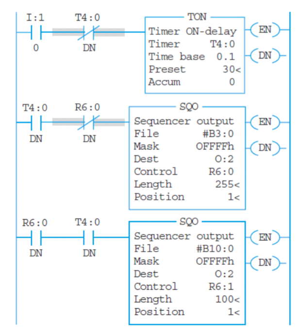
13. How many sequencer steps are there in the following LLD?
A. 255
B. 100
C. 521
D. 355
D
14. The total number of steps for SQO, SQC, and SQL are specified in the ____ section.
A. file
B. source
C. length
D. position
C
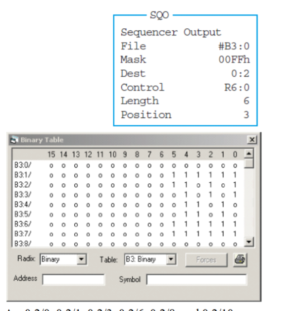
15. In the following figure, the position is at Step 3. Which output ports are energized
A. 0:2/0, 0:2/1, 0:2/3, 0:2/6, 0:2/8, and 0:2/10
B. 0:2/1, 0:2/3, 0:2/6, 0:2/8, and 0:2/10
C. 0:2/1, 0:2/3, 0:2/6, and 0:2/8
D. 0:2/0, 0:2/2, and 0:2/4
D
16. Which of the following statements is true?
A. R6:0/FD can be used in SQO instruction.
B. R6:0/FD can be used by SQL instruction.
C. R6:0/FD can be used by SQC instruction.
D. All of the above.
C
17. Which of the following statements is true?
A. R6:0/DN can be used by SQO instruction.
B. R6: 0/DN can be used by SQL instruction.
C. R6: 0/DN can be used by SQC instruction.
D. All of the above.
D
18. Which of the following statements is true?
A. R6:0/EN can be used by SQO instruction.
B. R6:0/EN can be used by SQL instruction.
C. R6:0/EN can be used by SQC instruction.
D. All of the above.
D
19. You can use register R6:0 as a control register in a sequencer output (SQO) instruction. T/F
T
20. The normally open contact R6:0/DN will close whenever the sequencer output (SQO) instruction is enabled.
F
21. The normally open contact R6:0/FD will close whenever the sequencer compare (SQC) instruction is enabled. T/F
F
22. File B3 may be used to hold the sequencer output (SQO) instruction’s patterns. T/F
T
23. The length parameter specifies the number of words in the sequencer file. T/F
F
24. You can step two or more sequencer instructions simultaneously. T/F
T
25. You must use the reset (RES) instruction to reset the SQO instruction. T/F
T
26. The .LEN and .POS can hold numbers up to 256 since an SQO can have up to 256 steps. T/F
T
27. There are 255 16-bit words in file B3. T/F
F
28. There are 255 16-bit words in file B10. T/F
F
29. The control registers used by sequencer functions SQO, SQL, and SQC are R6:0 through R6:255. T/F
T
30. The ______________________________ instruction transfers data from the sequencer source file to the
output destination module
SQO
31. The ______________________________ instruction is used to control several outputs with multiple step
patterns.
sequencer
32. PLC manufacturers use the table-to-register or file-to-word instruction instead of the
______________________________ instruction
sequencer
33. The normally open ______________________________ input must be closed to energize the sequencer
instruction.
enable
34. When the normally open ______________________________ input is closed, the sequencer instruction
resets to the first output pattern.
reset
35. A low-to-high pulse on the ______________________________ input causes the sequencer to advance to the
next output pattern.
step
36. The number of ______________________________ indicates the number of data patterns the sequencer
instruction must step through.
steps
37. The ______________________________ register holds the first data pattern.
starting
38. The ______________________________ register points to the step that the instruction is on.
step pointer
39. The ______________________________ register is an output group register that indicates the output
terminals on which data is placed.
destination
40. The ______________________________ parameter in the sequencer block holds the total number of steps
that must be completed before the sequencer done status bit (R6:0/DN) coil is energized.
sequencer length
41. The ______________________________ parameter indicates the step that is desired to start the sequencer
instruction.
sequencer position
42. The ______________________________ instruction reads input data from an input module or register and
then compares the input data to the step patterns in a bit data file (B3 or B10) or integer data file (N7).
SQC
43. The ______________________________ instruction is used to read the PLC input module and store the input
data in a file.
SQL
44. The number of sequencer steps can be increased by connecting two sequencers in a(n)
______________________________ arrangement.
cascading
45. The number of outputs that are controlled by the sequencer system can be increased by connecting sequencers
in ______________________________.
parallel