Unit 10 Common Collector
1/19
There's no tags or description
Looks like no tags are added yet.
Name | Mastery | Learn | Test | Matching | Spaced | Call with Kai |
|---|
No analytics yet
Send a link to your students to track their progress
20 Terms
What is the same as a Common Emitter?
The input to the circuit is still as the base and the same DC bias is required for the base, so R1 and R2 will set this.
We need to allow AC to pass into and out of the circuit while not allowing DC to pass, so C1 and C2 will do this as well
What is different?
the varying current through the collector does not need to be converted into a varying voltage because the output is no longer connected there so there doesn’t need to be a resistor.
The output is now connected to the emitter so R3 will now be there to convert the changing current into a changing voltage
There is no thermal runaway issue so C3 and R4 are not needed
What would happen if C3 was left in the circuit?
There would be no varying voltage at the emitter which would mean no audio output
VB is made more positive with NPN
current through the transistor increases
current through R3 increases
Voltage drop of R3 increases
The emitter moves farther away from ground (it becomes more positive
VB is made more positive with a PNP
Current through the transistor decreases
Current through R3 decreases
Voltage drop of R3 decreases
The emitter moves closer to ground (it becomes more positive, or less negative)
Voltage Gain
Low
Current Gain
High
Input Impedance (AC)
High
Output Impedance
Low

R1 and R2 purpose
Acts as a voltage divider to set the DC bias of the base and R2 affects the input impedance of the circuit
Allows amplification of entire waveform
Sets 0V at input to halfway between saturation and cutoff
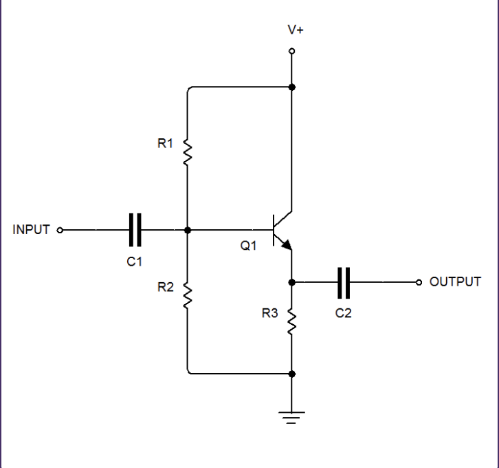
R3 Purpose
converts the changing current through the transistor into a changing voltage for the output

C1
Allows AC (Input signal) to pass into circuit
Blocks DC from getting into circuit and changing DC bias of base set by R1 and R2
Blocks DC bias set by R1 and R2 from getting out to what is connected to the input
C1 is a part of the input impedance
Typically a large enough value that all audio passes without voltage drop

C2
Blocks DC that is in AC+DC at collector from going out the output
Typically a large enoguh value that all audio passes without voltage drop
C2 is a part of the output impedance
What is apart of the input impedance?
Forward biased base-emitter junction, R2, R3, C1
What connected to R3 (the resistor that converts a changing current into a changing voltage)
C2, emitter, ground
In a common collector circuit utilizing an NPN transistor, the collector is connected to
V+
the input connects to the
base
the output connects to the
emitter
V-/+ connects to the
collector
what is the difference between common emitter and collector?
There is no extra resistor at the V+/V-. The collector is connected directly to the voltage source. The output is also connected to the emitter so there is a resistor from the emitter to ground to covert the changing current into a changing voltage. There is no thermal runway so C3 is not needed and if it is included, it can cause problems with the audio at the output.