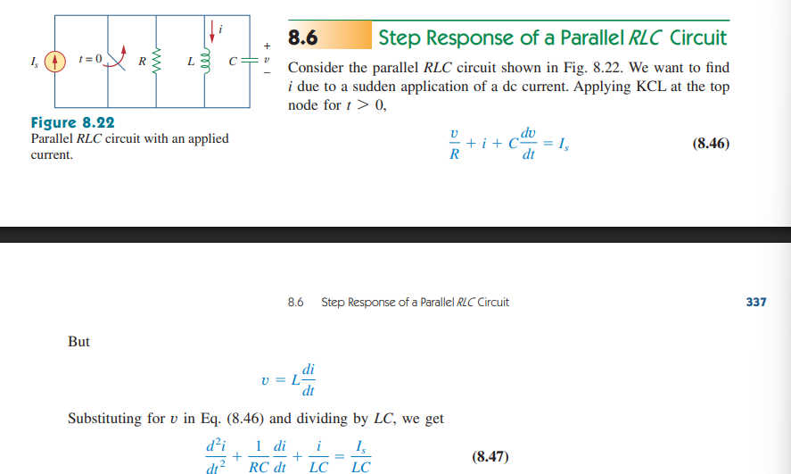
8.6 Step Response of a Parallel RLC Circuit
1/3
There's no tags or description
Looks like no tags are added yet.
Name | Mastery | Learn | Test | Matching | Spaced | Call with Kai |
|---|
No analytics yet
Send a link to your students to track their progress
4 Terms
The Step Response of a Parallel RLC Circuit
A parallel RLC circuit with a step response will be initially disconnected from a current source until it is connected at t = 0+.
From there, we apply KCL at the nodes to acquire our equations.
Final Current Response for a Step-Response Parallel RLC Circuit
Like with all previous cases, the final response of the current through the inductor in a series of parallel RLC elements is given by the sum of the transient response and the steady-state value.
Auxiliary Equation/Initial Conditions
We need three forms of information to solve for the coefficients of our current response function:
V(0)
The initial capacitor voltage at t = 0 (steady-state conditions)
I(0)
The initial inductor current at t = 0 (steady-state conditions)
The Differential Term
This time, we utilize the voltage-inductor relationship (since we are solving for the inductor’s current after all, same as how we use the current-capacitor relationship to solve for the capacitor’s voltage).
filler
filler stuff filler filler rrrrrrrrrrrrrrrrrrrrrr rewfiller