RADTH 305 Final Exam Flashcards - Combined (Modules 4 + 5 )
 Call Kai
 Learn
Learn Practice Test
 Spaced Repetition
 Match
Match Flashcards
 Knowt Play
1/119

Earn XP
Description and Tags
RADTH 305 - MRI Physics. University of Alberta
Name | Mastery | Learn | Test | Matching | Spaced | Call with Kai |
|---|
No analytics yet
Send a link to your students to track their progress
120 Terms
What is the B0 fringe field value below which there are no safety concerns?
The fringe field threshold at which there are no safety concerns for the general public is 5 gauss (0.5 mT). The 5 gauss line is the outside boundary outside which pacemakers, implants, and the general public are considered safe. Inside the the 5 gauss line, ferromagnetic attraction, device malfunction, and other safety risks become relevant
some places have a 9 gauss line as well
define and explain DSV
DSV (diameter of spherical volume) is the diameter of an imaginary sphere around isocenter where the magnetic field’s homogeneity meets specification requirements. manufacters specifiy that the magnetic field is uniform within a certain tolerance (3 ppm) inside the DSV.
defines the usable region of high-quality homogeneity for imaging
What is the advantage of a shielded gradient coil over an unshielded one?
the shielded gradient coil has an additional shielding winding that produces an opposing magnetic field outside the gradient coil. it reduces eddy currents in nearby conductive structures which results in less image distortion.
This allows for faster gradient switching because the system doesn’t have to wait eddy currents to decay. This is mandatory for EPI sequences that rely on rapid gradient switching
Name two potential hazards of the gradient system for the patient
Peripheral nerve stimulation
rapidly switching gradients induce electric fields in patient’s tissues which can cause involuntary muscle twitching, tingling, or discomfort.
At higher levels this is painful, so limits are enforced
Acoustic noise (hearing damage)
fast gradient switching causes loud mechanical vibrations in the gradient coils.
Sound levels can exceed 110-130 dB, posing a risk of temporary or permanent hearing loss without proper ear protection
Gradient Induced Heating (minor compared to RF)
rapidly switching gradients induce eddy currents in the patient, which can lead to tissue heating
What is a Faraday Cage? Describe the design
Faraday cage is a continuous conductive enclosure—typically made of copper or aluminum—that blocks electromagnetic fields by redistributing electrical charges across its surface. In MRI suites, the room itself functions as a Faraday cage, with metal shielding on the walls, ceiling, and floor that is fully bonded to avoid any gaps. RF-shielded doors, mesh-shielded windows, and a filtered penetration panel allow controlled access while preventing RF leakage. Waveguides are used for ventilation ducts (long metal tubes that block RF frequencies and filters are used for electrical cables to stop RF noise. This design keeps external radiofrequency noise from entering the MRI environment and prevents the scanner’s RF energy from escaping the room.
Why do we need a strong magnet for MRI
Higher magnetic field means increased SNR, and increased SNR means
higher resolution images
faster imaging
more imaging techniques (diffusion MRI, fMRI, cardiac MRI)
more contrasts: SWI and spectroscopy
Convert 5 Gauss to SI units
1 gauss = 0.0001 T
5 Gauss = 0.0005 T = 0.5 mT
How Strong is Earth’s magnetic field?
0.3 - 0.7 G
30-70 uT
name three types of magnets
Superconducting magnetic
Use coils cooled to very low temperatures so they have zero electrical resistance. This allows for very high, stable, magnetic fields with low operating power. These are the most common in clinical MRI
Permanent magnets
Made of ferromagnetic materials that produce a constant magnetic field without power. They are simple and stable but extremely heavy and limited to low field strengths (typically 0.2-0.4T)
This is a steady magnet but the field with drift with temperature and may change over time
Electromagnet (resistive magnet)
Uses electric current through copper coils to generate the field. It can be switched on and off but requires continuous high power and cooling, so it is generally limited to low field strengths
Field is only as stable as the current that is supplying it
give one pro and one con of permanent magnets for MRI
Pro: require no power or cryogens, making them simple, stable, and relatively inexpensive to operate.
Con: prone to field drift, magnetic field can change over time due to temperature or environmental effects
What is a Halbach ring?
A Halbach ring is an arrangement of permanent magnets designed to create a strong magnetic field on one side while canceling the field on the opposite side. This configuration is often used in applications like MRI systems and particle accelerators to achieve efficient magnetic field management.
strong homogenous field on one side and weak fringe field on the other
what is a cryostat?
A cryostat is the insulated vessel that houses the superconducting magnet and keeps it at extremely low temperatures (below 9K) using liquid helium so coils remain superconducting. It prevents heat transfer, maintains the cryogenic environment and contains the helium bath. Also has various insulating and vacuum layers to shield the coil from the warm environment
What is a coldhead?
A cold head is the cryocooler device that recondenses helium gas back into liquid inside the cryostat. It continuously removes heat from the system, reducing helium boil off and helping maintain the magnet at super conducting temperature
name 2 pros and 2 cons of superconducting magnets
pros: strong, stable, homogenous magnet
cons: expensive, large fringe field, higher safety concern of eddy currents and energy deposition
Describe 2 ways a magnet can be shimmed
Active shimming: using shim coils with adjustable electric currents to fine tune and homogenize the magnetic field
passive shimming: placing small pieces of ferromagnetic material around the main magnet to correct for field inhomogeneities
describe 2 types of magnetic shielding
Active shielding: uses additional superconductive coils to generate an opposing field. Actively cancels out the outer fringe field, allowing for a more compact magnet footprint
Passive Shielding: using ferromagnetic materials (steel) around the magnet room to contain and redirect the fringe field. Reduces how far the magnetic field extends outside the scanner
describe the gradient system in MRI
The gradient system consists of three orthogonal gradient coils (X,Y,Z) inside the bore that produce small, linearly varying magnetic fields. These gradients are rapidly switched on and off to encode spatial information, enabling slice selection, frequency, and phase encoding, and image formation
Describe gradient strength and give a typical value/range
the maximum amplitude of the gradient field
10-50 mT/m - will be higher for diffusion MRI
describe rise time and give a typical value / range
the time required for the gradient to go from 0 to maximum strength
300 us
describe slew rate and give a typical value / range
how quickly the gradient can change it’s strength (dG/dT)
20-200 T/m/s
describe linearity and give a typical value / range
how accurately the gradient volume field changes in a perfectly linear manner across the imaging volume
0.1 %
describe maximum duty cycle and give a typical value / range
the percentage of time the gradient can be active at high power without overheating
60-80%
What are eddy currents and what problems can it cause
Eddy currents are unwanted electrical currents induced in nearby conductive materials when gradients switch rapidly. They create secondary magnetic fields that distort the intended gradients, leading to image artifacts, geometric distortion, and slowed gradient responses.
what are 3 ways to mitigate eddy currents and their effects
pre-emphasis (pre-shape wave form to account for it)
active gradient shielding
reduce inductance (L) in design of gradients
give an example of an eddy current related artifact
Metal from hearing implants or dental crowns can develop eddy currents when exposed to switching gradients, producing magnetic field distortions. This causes signal voids, geometric distortion, and blurring around the metal, typically seen as dark, misshapen regions or streaking near the implant or crown.
Why does gradient non-linearity occur?
Real gradient coils cannot produce a perfectly linear magnetic field over the entire imaging volume. The physical design and geometry of of the coils only approximates linear fields near isocenter, so further from from centre the field deviates from ideal linearity.
what is a consequence of gradient non-linearity?
Geometric distortion: structures appear stretched, compressed, or shifted, especially toward edges of FOV
Why is a high voltage required in gradient amplifiers?
Gradient coils behave like inductors (resist change in current), the voltage determines how quickly the current can change. A higher voltage lets the system change current faster, which allows for faster gradient ramp times.
give 2 advantages of array coils
higher SNR
multiple sensitive small coil elements placed close to the patient give higher sensitivity than a large single coil
parallel imaging capability
array coils allow for accelerating imaging (reducing amount of k-space lines collected), reducing scan times and motion artifacts
compare receive only (Rx) and transmit/receive (Tx/Rx) coils
Rx Coils: used to collect MR signals only
pros: smaller, fit closer to patient to maximize SNR, use in arrays
cons: require seperate Tx coil to transmit RF
Tx/Rx Coils: both transmit RF pulses and receive signals
pros: can be used independently, no sperate Tx coil needed
cons: usually larger, lower SNR than small Rx-only elements. slower imaging
Explain gradient non-linearity and it’s consequences
Gradient non-linearity occurs when the magnetic field produced by gradient coils is not perfectly linear across the imaging volume. Ideal linear gradients only exist near the isocenter, farther away the field deviates from the intended linear slope. Consequences include geometric distortion (structures appear stretched or shifted at edge of FOV) and spatial misregistration (voxels mapped incorrectly, affecting measurement accuracy)
Describe an RF transmit amplifier
RFPA boosts the low-power radiofrequency signal from the MRI system to a high-power pulse capable of exciting the nuclear spins in the patient. It drives the transmit coil to generate the B1 field needed for MRI with precise control over amplitude, phase, and duration of RF pulse. Amplifies signal by a factor of 100 (1 V signal from computer → 100 V signal)
Describe an RF receive amplifier
A Low-Noise Pre-Amplifier boosts the very weak signal detected by the receive coils. It amplifies the signal without adding significant noise, ensuring high SNR before signal is digitized for image reconstruction.
RF Pre-amp will send signal to a demodulator which will extract the encoded information from the amplified RF signal.
what is the purpose of the Tx coil? Give one desirable characteristic
The purpose of the Tx coil is to generate the B1 magnetic field that excites nuclear spins during an MRI sequence. A high field homogeneity may be desirable across the imaging volume to to ensure uniform spin excitation
Why are there a wide variety of Rx coils?
Because different coils are optimized for specific anatomy, size, and imaging requirements. Smaller specialized coils provide higher SNR for localized regions while larger or flexible coils cover multiple body parts / areas. Arrays allow for parallel imaging and faster acquisition
Describe the basic circuit of an RF coil
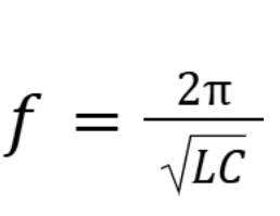
The basic circuitry of an RF coil is a resonant LC circuit consisting of
Inductor (L): the coil itself, generating the magnetic field
Capacitor (C): tunes the circuit to the desired Larmor frequency
Resistor (R): represents coil loss of energy/current
Circuit resonates at the Larmor Frequency to efficiently transmit or receive MR signals
Give two examples of RF volume coils
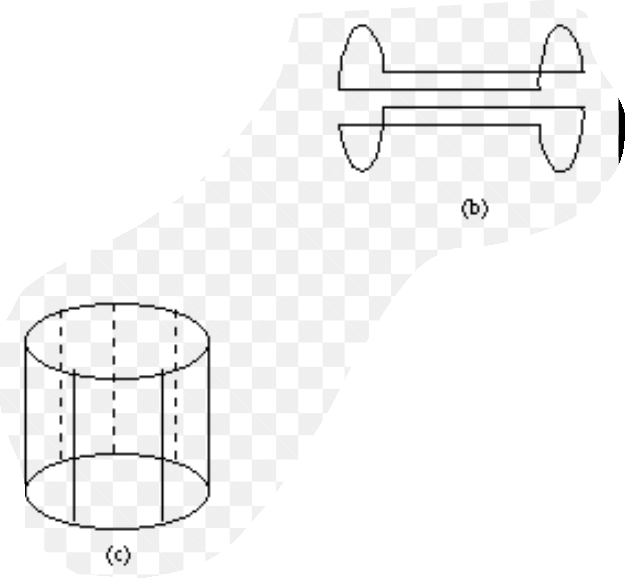
Birdcage Coil: cylindrical coil with longitudinal rungs connected by end rings. Produces a homogenous B1 field inside the cylinder, commonly used for head, wrist, or body imaging as a volume coil
Saddle Coil: two curved coils shaped like a saddle on opposite sides of the target. Generates a linearly polarized B1 field, less homogenous than the bird cage. Often used for small animal imaging or localized Tx/Rx
What is a CP Coil?
Quadrature (Circularly Polarized - CP) Coil
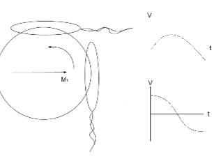
Transmit: produces a rotating Rf field rather than a single axis oscillating field to excite the nuclei more efficiently
Receive: the rotating magnetization induces signals in two coils placed 90 degrees to each other, creating a two channel system with a combined signal, giving a stronger and cleaner signal
What are the two advantages of a CP coil
The transmit coil requires root 2 less power and the receive coil has an SNR improvement of root 2.
overall uniformity and efficiency for both transmission and reception
Can you use a 1.5 T coil on a 3 T system?
You cannot use a 1.5 T coil on a 3T system because coils are tuned to the Larmor frequency of a specific field strength. A 1.5 T coil is tuned for 64 MHz while a 3 T field has a resonant frequency of 128 MHz. Using the wrong coil will result in low signal and inefficient excitation and reception.
What is the purpose of an array coil?
Phased array coils = multiple coils and pre-amps create and detect multiple signals. These images can then be added together
Increase SNR: multiple small coil elements placed in close proximity to the anatomy detect more signal than a large coil
Enables parallel imaging: allows accelerated imaging to reduce scan times and motion artifacts
Covers larger areas: combining multiple elements, arrays can image larger regions while maintaining high sensitivity
What is a matrix coil?
A matrix coil is a large array coil made of many small overlapping coils, where you select what coils you want to use for the specific scan. It allows for parallel imaging, improves SNR, and allows imaging of different body parts without physically changing coils
Name five desirable characteristics of an MRI scan
high SNR
high spatial resolution
fast imaging
artifact free imaging
appropriate contrast / High CNR
Name at least 4 ways to increase SNR
Increased B0: higher field → stronger signal = increased SNR
Smaller / custom Rx coil: reduces noise and closer to patient = detects more signal
Increase voxel volume: more signal is received, with the tradeoff of lower resolution
Increase number of signal averages (NSA/NEX): repeating scans and averages reduces noise, but takes longer to finish scan
Increase FOV while keeping number of pixels the same: increase pixel size, increases SNR
Decrease bandwidth: reduces noise, ½ bandwidth = root(2) reduction of noise
Define/explain CNR
CNR measures how well two different tissues can be distinguished in an image relative to the background noise. It is the difference in signal between two tissues divided by the noise level. Higher CNR means better ability to see contrast between structures
Name at least 4 ways to increase image resolution
Smaller voxel size: resolution is inversely proportional to voxel size. So decreasing volume increases resolution
Smaller FOV while keeping number of pixels same: voxels become smaller, resolution increases
Larger Matrix: going from 128 → 256 matrix size reduces pixel size by 4x, but signal will also be reduced by factor of 4
Thinner slices: improves through-plane resolution
Go further out into k-space edges: edges = resolution, center = contrast
what is the scan time formula for 2DFT images (GE, SE)

What is the scan time formula for 3DFT images

What is the scan time formula for FSE

What is the scan time formula for EPI

How does signal averaging (NSA) affect SNR and scan time
SNR increases by the square root of number of averages
Scan time increases linearly with number of averages

How can slice thickness affect CNR?
The optimal contrast is when the slice thickness is the same size as the lesion. Larger slices will increase the amount of signal collected (increasing SNR), which can improve CNR as both tissues produce stronger signals relative to noise. However, thicker slices also reduce contrast between adjacent structures due to the partial volume effect (two tissues in same voxel washes out contrast)
Explain the trade-off between spatial resolution and SNR
Higher spatial resolution requires smaller voxels, but smaller voxels capture less signal, reducing SNR
Increase resolution → smaller voxels → lower SNR
Increase SNR → larger voxels → lower resolution
One must balance detail (resolution) with image quality.
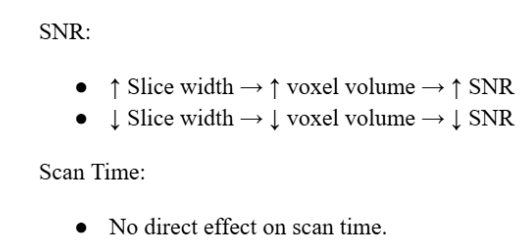
How does Slice Width affect SNR and scan time
how does Matrix size affect SNR and scan time
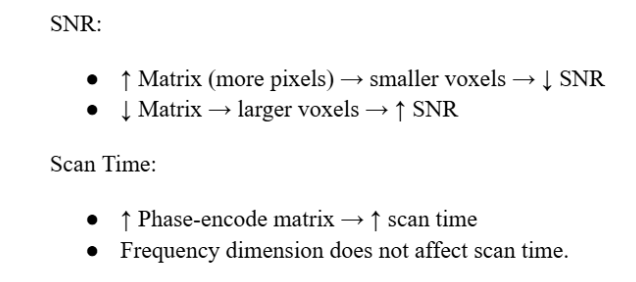
How does FOV affect SNR and scan time
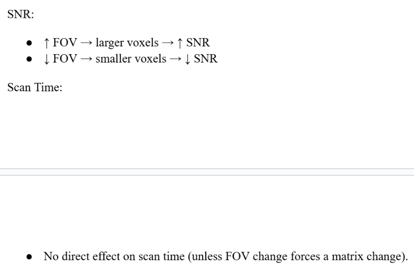
how does pixel bandwidth affect SNR and scan time?
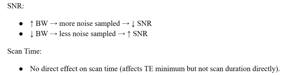
rank these pulse sequences from slowest to fastest: EPI, GE, FSE, SE
SE < GE < FSE < EPI
how does doubling the number of averages (NEX/NSA) affect SNR
Doubling the number of averages (NEX/NSA) increases the Signal-to-Noise Ratio (SNR) by a factor of the square root of 2, which improves the image quality by reducing noise.
how does doubling the number of averages (NSA/NEX) affect total scan time
Doubling the number of averages doubles the total scan time (2× longer).
give three acronyms of organizations involved in MR-RT
CADTH
Canadian Agency for Drugs and Technologies in Health
CPQR
Canadian Partnership for Quality Radiotherapy
ISMRM
International Society for Magnetic Resonance in Medicine
Name a cancer centre in Canada that currently has a MR-LINAC in use
Arthur J Child Comprehensive Cancer Centre
Princess Margaret Cancer Centre
Odette Cancer Centre
What is the MOMENTUM Study?
An international registry that collects clinical, imaging, technical, and patient reported data from patients treated with MR-guided radiotherapy to evaluate the safety, feasibility, and clinical benefit of MR-guided adapted radiation therapy and supporting evidence-based adoption of the technology.
Define margin reduction in the context of MR-RT
Margin reduction refers to decreasing the planning target volume (PTV) margins around the tumor because real-time MRI visualization, daily adaptive planning, and improved soft tissue contrast reduce set-up uncertainty, organ motion, and anatomical variation, allowing for more precise targeting while sparing normal tissue
Define dose escalation in the context of MR-RT
Safely increasing the radiation dose to the tumor by using real-time MRI guidance and daily adaptive planning to account for anatomical changes and motion, improving target coverage while maintaining normal tissue dose constraints
Define target delineation in the context of MR-RT
The process of accurately identifying and outlining the tumor and relevant target volumes (GTV, CTV, PTV) on imaging to ensure the prescribed radiation dose delivered to the intended area while minimizing dose to surrounding normal tissues
Define tumor tracking in the context of MR-RT
The continents or near-real-time monitoring of tumor position using MRI during radiation delivery, allowing the beam to be gated or adapted to tumor motion (ex. respiration) to maintain accurate dose delivery and reduce irritation of surrounding normal tissues.
List at least four differences between diagnostic MR and MR-Sim Equipment
patient positioning
MR-Sim allows treatment position using flat tabletops and immobilization devices whereas diagnostic MRI uses curved tables for comfort
RF Coils
Coil bridges are often used on patients to prevent deformity of patient outline
Geometric Accuracy
MRI systems prioritize geometric fidelity and distortion correction for RT planning, while diagnostic MRI prioritizes image contrast and diagnostic quality
Laser Systems
MR-Sim includes external laser alignment systems for reproducible patient setup and reference marks; diagnostic MRI does not
Comfort
diagnostic MRI has cushions on the treatment couch, MR-Sim does not as we are using immobilization devices
Bore Size
the bore in an MR-Sim is larger than diagnostic MRI so that immobilization devices can fit in machine
Describe the electron return effect in terms of it’s physics and RT significance
In MR-guided radiotherapy, the strong magnetic field causes secondary electrons produced by photon interactions to curve due to the Lorentz force. At tissue-air interfaces, electrons that would normally exit the patient are bent back toward the tissue, leading to increased electron fluence at the interface. The ERE results in dose enhancement at tissue-air interfaces (skin, lung, bowel gas) and potential dose reduction just beyond the interface, which can increase the risk of skin or interface toxicity and must be accounted for during treatment planning and dose calculation
what three factors affect the ERE
Direction of B0 relative to beam
magnitude and location of dose enhancement depends on orientation
Strength of B0 field
higher field strength causes greater electron deflection, increasing ERE severity
prescence and size of air cavities
ERE occurs in tissue-air interfaces, larger or more numerous gaps (lungs, skin) will increase effect
What two MR-LINACs are minimally affected by ERE and why?
Aurora-RT
electrons experience less lateral deflection as their velocity is aligned with the magnetic field
ViewRay MRIdian
lower field strength causes less deflection of secondary electrons
which MR-LINAC is most affected by the ERE
Elekta Unity
has a higher magnetic field strength and a B0 field oriented perpendicular to the photon beam, which causes greater lateral deflection of secondary electrons at tissue-air interfaces
give 5 main features of the ViewRay MRIdian system
6 MV Beam
0.35 T split superconducting magnet
magnet perpendicular to the beam
bore is 70 cm wide
couch moves in three directions
system is commercially available and there are many clinical publications on it
give 5 main features of the Aurora-RT System
6 MV beam
0.5 T biplanar Tc superconducting magnet with steel yoke
magnetic field is parallel to the photon beam
bore is 110 cm wide
couch moves in three direction
not commerally available with no clinical outcomes published
give 5 main features of the Elekta Unity System
7 MV beam
1.5 T closed superconducting magnet
magnet perpendicular to the beam
bore is 70 cm wide
commercially available and has many clinical outcomes
In the Elekta system, how is the system engineered so that the beam reaches the patient unobstructed by the magnet
The LINAC and gantry rotate around the MRI magnet in the Unity machine, and the photon beam passes through the magnet via a coil-free central gap in the magnet design. Specifically, the central 15 cm of the magnet contains no coils, creating a clear path for the radiation beam. This gap allows a maximum field size of approximately 24 cm in the head-to-toe (superior–inferior) direction at isocentre.
Although the beam passes through the magnet structure, the total material in the beam path is minimized and is equivalent to about 8.2 cm of aluminum, ensuring acceptable beam attenuation and dose delivery.
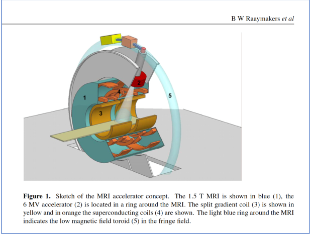
In the Viewray system, how is the system engineered so that the beam reaches the patient unobstructed by the magnet?
The MRI magnet is split into two halves, creating a central open gap at isocentre. The radiation beam passes directly through this gap rather than through the magnet structure, allowing it to reach the patient unobstructed and with minimal attenuation, while still maintaining the magnetic field required for MRI guidance.
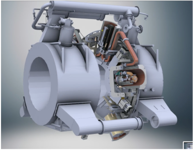
In the Aurora-RT system, how is the system engineered so that the beam reaches the patient unobstructed by the magnet
The MRI magnet is designed such that the B₀ magnetic field is always parallel to the photon beam. To achieve this, the magnet rotates together with the treatment gantry, ensuring that the beam path remains aligned with the magnetic field at all times. As a result, the radiation beam passes directly through the magnet without obstruction or attenuation, regardless of gantry angle, allowing continuous, unobstructed delivery of the prescribed dose.
Give the field strength and beam energies of 3 different MR LINAC Systems
ViewRay MRIdian: 6 MV beam and 0.35 T magnet
Elekta Unity: 7 MV beam and 1.5 T magnet
Aurora-RT: 6 MV beam and 0.5 T magnet
Australia MR-LINAC: 6 MV and 1.0 T magnet
Give the field orientation of three different MR LINAC systems
ViewRay MRIdian: split superconducting perpendicular
Elekta Unity: superconducting closed bore perpendicular
Aurora-RT: rotating superconducting parallel magnet
Australia: superconducting open bore parallel and perpendicular orientation.
The patient rotates in this machine!
Which was the first commercially available MR-RT Machine?
ViewRay MRIdian received FDA clearance in 2012. It combined a 0.35 T MRI scanner with a linear accelerator for real-time imaging and adaptive radiation therapy.
Name three disadvantages of CBCT vs. MRI for MRgRT applications
Poor Soft Tissue Contrast: limited differentiation between tissues, making it harder to visualize tumors/OARs
Limited Real Time Imaging/Motion Tracking: CBCT acquires images slowly and cannot continuously monitor tumor motion during treatment. Compare this to MRI that allows for real-time visualization and gating of moving targets
Higher Imaging Dose: CBCT uses ionizing radiation, MRI is non-ionizing
why is MRI particularly useful for proton therapy?
It provides superior soft-tissue contrast for accurate tumor and organ-at-risk delineation, which is critical in proton therapy due to its sharp dose fall-off (Bragg peak). Small errors in target definition or positioning can lead to significant underdosing of the tumor or overdosing of nearby normal tissue, so MRI’s high-resolution imaging helps maximize treatment precision and safety.
Describe a standard RT workflow without MRI
A typical radiation therapy workflow involves patient consultation, treatment planning using CT imaging, verification of patient positioning, administration of radiation doses, and follow-up assessments.
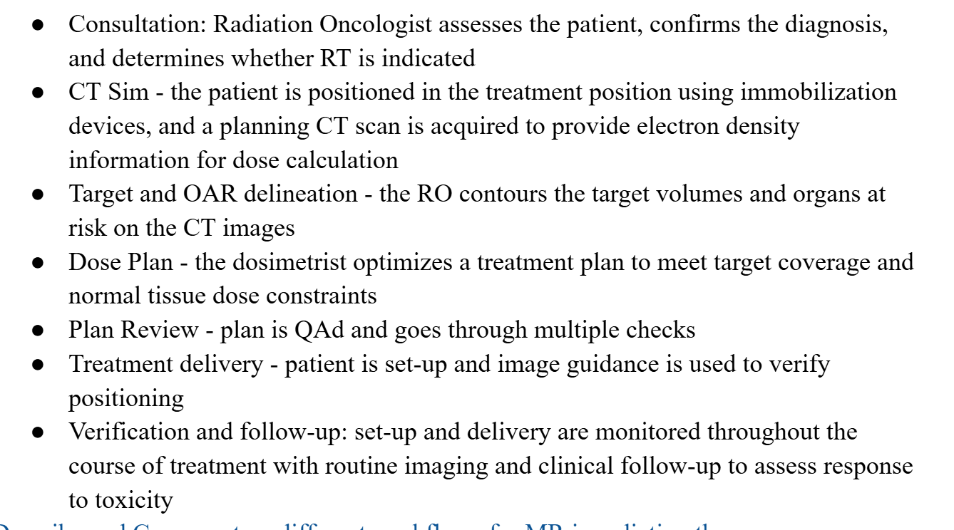
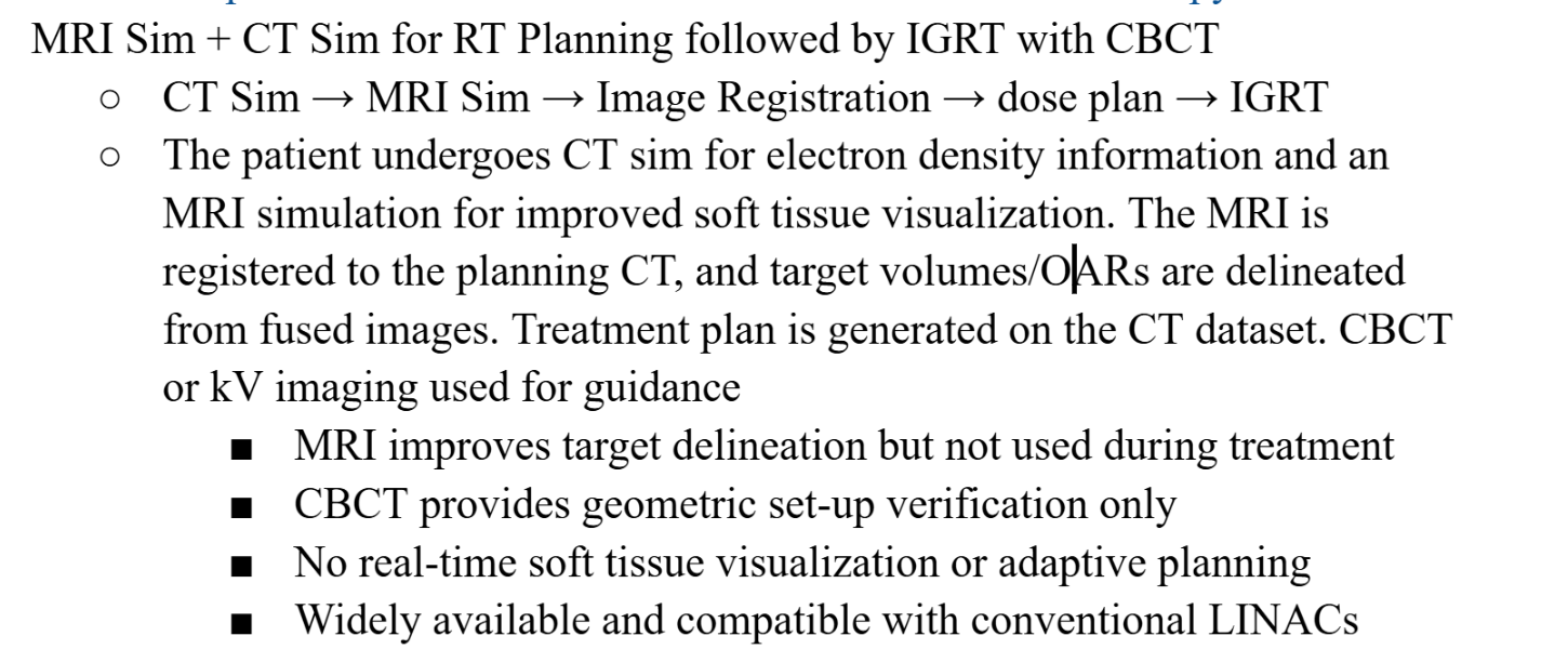
Describe the MR-CTgIGRT workflow
Descibe the MRgRT workflow
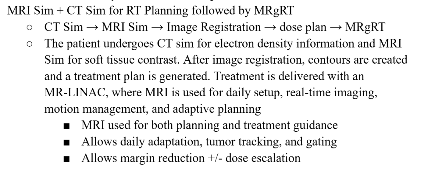
What are some pros of an MR-only workflow
improved target localization
real-time tracking/gating possible
normal tissue sparing
adaptive planning
fMRT= bioguided RT
decreased fractionation
what are some cons of an MR-only workflow
complications from tissue overdose
decreased dose rate (600 MU/min c.f 1200 MU/min)
slower gantry rotation
decreased field size
What is adaptive RT and when/who might it be useful for
ART is an approach in which the radiation treatment plan is modified during the course of the treatment to account for changes in patient anatomy, tumor size/shape, or organ motion using updated imaging. ART is particularly useful when there are significant anatomical or biological changes, such as tumor shrinkage/progression during tx, daily organ motion/deformation, weight loss or body contour changes, targets near critical organs where maintaining dose constraints is prioritized, and for pediatric patients who have rigorously regulated dose prescriptions to minimize long term effects
What does the term PseudoCT mean
A pseudoCT is a synthetic CT image generated from MRI data that assigns CT-like electron density (HU) information to tissues. This is how dose calculations are performed in MRI-only workflows, where conventional planning CTs are not acquired.
Define and Explain ATS
ATS (Adapt-to-Shape) is an online adaptive radiotherapy workflow used in MRgRT. It involves re-contouring the target and organs at risk on the daily MRI to reflect the patient’s current anatomy, followed by full reoptimization of the treatment plant before delivery. This accounts for anatomical changes such as organ deformation, tumor shrinkage, or variable filling. This ensures accurate target coverage while maintaining normal tissue dose constraints.
Define and Explain ATP
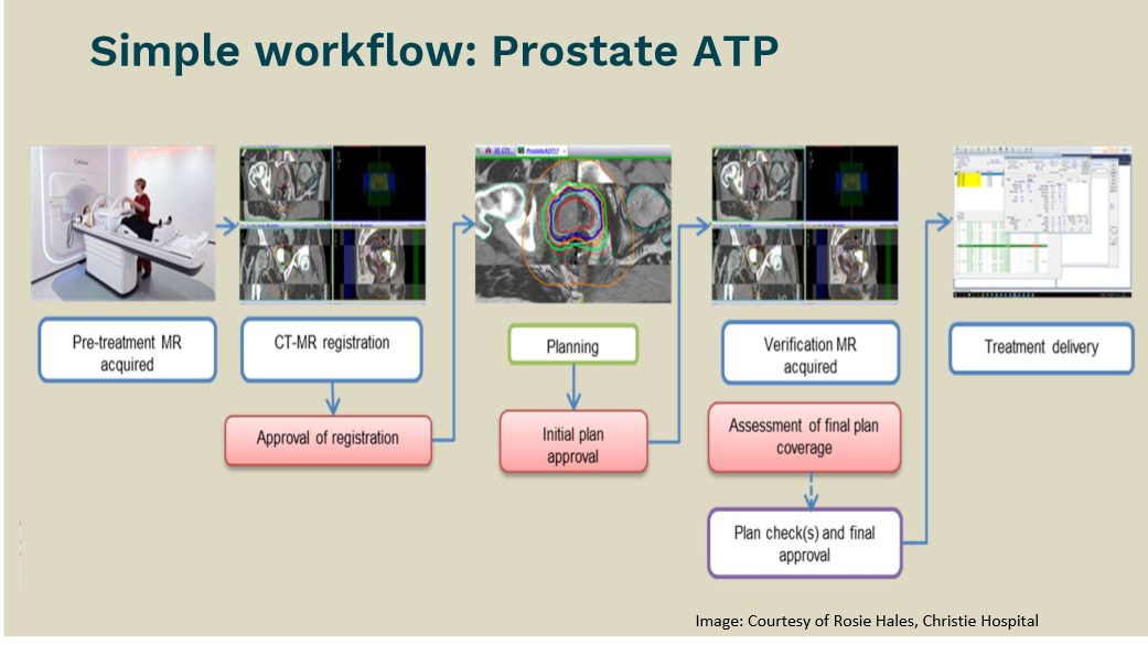
ATP (Adapt-to-Position) is an online adaptive radiotherapy workflow used in MRgRT. It involves shifting or re-optimizing the existing treatment plant based on the daily position of the target seen on MRI, without changing the target or OAR contours. The plan is adapted to account for rigid translational shifts and limited rotations while the shape of the anatomy is assumed to be unchanged.
When is ATP more useful? When is ATS more usful?
ATP is faster and less resource-intensive than Adapt-to-Shape (ATS) and is more useful when anatomy is stable but target position varies from day to day.
ATS is useful when shape and position of structures change significantly from day-to-day, but it is more time and resource-intensive than simpler adaptive approaches.
Draw a flowchart for a generic online MR workflow
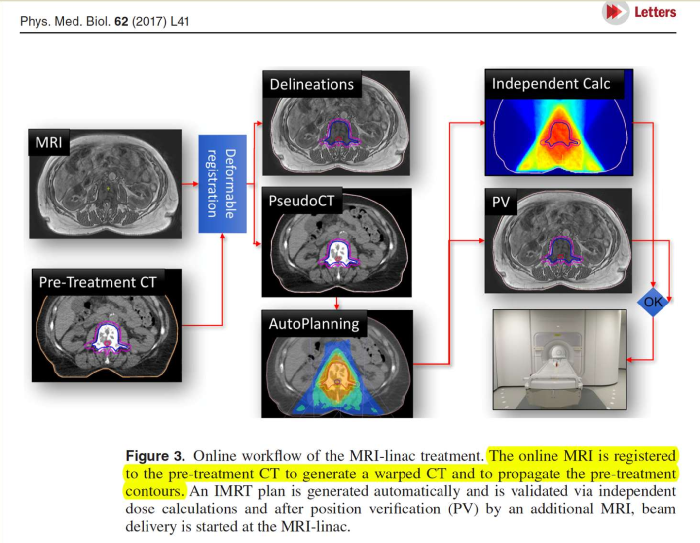
Draw a flowchart for an online prostate-ATP workflow
draw a flowchart for an online pelvic-ATS workflow
pretreatment CT taken to give electron density and a daily MRI is taken. They are combined in deformable registration so that the CT is adapted to the current anatomy seen on the MRI. Contours are then retraced based on today’s MRI and densities are applied to areas of concern (bladder). The online part is where the doses are replanned according to the combined CT/MRI data , then a conformational MRI and dose calcs are done for QA. Treatment is delivered at the same time as an MRI to ensure if the patient moves the dose is shifted. A post treatment is then done to confirm dose was delivered to the right spot

what is an imaging biomarker, and why is this of interest in MR-RT?
An imaging biomarker is a quantitative feature extracted from medical images (signal intensity, diffusion, perfusion parameters) that reflects biological processes, disease characteristics, or treatment response. In MRgRT, imaging biomarkers are valuable MRI acquired during treatment can monitor tumor responses, cellularity, or perfusion in real time. This enables response-adapted treatment like modifying the dose or margins to improve tumor control or minimize toxicities
MR is not sensitive to electron density (which is needed for treatment planning). How do MR-only workflows get around this?
MR-only workflows address this by generating a pseudoCT from the MRI, where tissues are assigned CT-equivalent electron density or Hounsfield unit values using methods such as atlas-based approaches, tissue classification, or machine learning. This synthetic CT enables accurate dose calculation without a planning CT needed.
What is the topic of AAPM TG-284
this task group reported on MRI simulation in radiotherapy. it provided recommendations for clinical implementation, optimization, and quality assurance of MR-Sim in RT. It includes guidance on equipment selection, siting, commissioning, workflow integration, motion and distortion management, safety, and imaging protocols tailored for RT planning
Explain three unmet needs in MR-SIM from the AAPM TG-284 paper
incomplete geometric distortion correction
While vendors provide 3D gradient nonlinearity (GNL) correction, it is not available for all imaging sequences (e.g., 2D, gated, DWI), may not be applied retrospectively, and residual distortions remain at large fields of view with no vendor-provided solution.
Limited B0 field mapping and correction
Online B₀ field mapping is often restricted to research options, may rely on wrapped phase images, and patient-specific online distortion correction is not clinically available.
Residual Intensity Non-Uniformity
Vendor correction algorithms reduce RF coil intensity variations but residual inhomogeneities remain, affecting image registration and segmentation; clinical correction tools are limited.