VL IX - Power electronics
1/64
There's no tags or description
Looks like no tags are added yet.
Name | Mastery | Learn | Test | Matching | Spaced | Call with Kai |
|---|
No analytics yet
Send a link to your students to track their progress
65 Terms
Difference between electrical and information transport
minimum loaa of energy for energy transport
What does PWM mean
Pulse Width Modulation
V×s theorem
Voltage can be controled by duty cycle
definition of duty cycle term:
Duty cycle = ton/T
T = ton + toff
whats pulse width modulation
modification constant signal into alternating sinusoidal signals
PWM for AC
through suitable modelling of duty cycle AC can be generated
Demodulation of signal by motor inductances
Smoothness can be set via switching frequency
» Required for power electronics
different type of switches
only activatable
Actively controllable
Uncontrolled
why are semiconductor switches necessary
Regular switches would be to slow
where is a rectifier used
AC to DC
used in onboard charger
how does a rectifier work no smoothing
Using 4 diodes the current is kept positiv
disadvantage high voltage fluctuation
How to smooth rectifier
using inductive or capacitive smoothing
If smoothing is large enough it is considered a constant voltage source
pros and cons of smoothed rectifier
Pros:
constant output voltage
Cons:
harmonic waves have feedback on grid
Only usable for low power applications
what does obc mean
Obnboard charger
Step by step how OBC works
rectifier converts AC to DC
DC Converter adapts DC to HV-DC
Contains high frequency transformer for safety reasons
Bidirectional AC/DC + bidirectional DC/DC + control + grid/communications regulations
V2G applications possible
components of DC/DC (Buck) converter
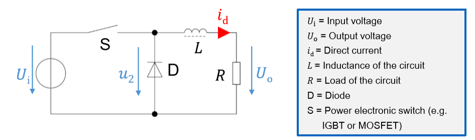
Operation cycle 1 DC/DC converter
Switch S closed
Coil L is charged
Current flow through L and R driven by voltage
Diode D is blocking
operation cycle 2 DC/DC Converter
Switch S is opened
Coil L is discharged
Diode D is forward bias
Types of DC/DC converter
Buck
Boost
Buck Converter Mode of Actions
Switch closed
Current increases exponentially
Switch open
Current drops exponentially
Ratio between working cycles determines effective output current
Boost Converter Components
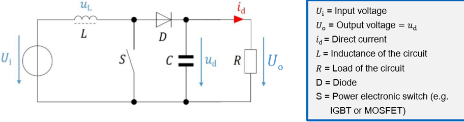
Mode of Operations Boost converter
Coil L provides voltage, which ads to input voltage
Coil L charged in the first and discharged in the second cycle
Smoothing of output cycle through capacitor C
Cycle 1 Boost converter
Switch S is closed
Coil L is charged
Current flows through L and S
D is blocking
Load R is buffered via backup Capacitor
cycle 2 boost converter
Switch S is open
Coil L discharges through D, C and R
D is forward biased
problems caused by DC/DV Ripple
Overvoltage on sensitive components
Strong noise for sensitive analog components
Noise generation
Flashes of light
how trade of reduction of DC/DC ripple
increasing switching frequency
more switching losses
inverter DC/AC mkde of operation
Three phase AC required
Power electronic switches used for conversion
Reversible operating principle
what are the different Inverter numbers affected by
Voltage by duty cycle and DC-link voltage
Frequency by motor speed
Switching frequency affects current ripple
Power factor inverter causes and consuquence of low power factor
If current and voltage are not in phase reactive power generated
Low factor » higher RMS current required for same power
On what to adjust AC voltage for inverter
specification of maximimum DC-Voltage
Or
Specification of the maximum RMS of AC-voltage
on what to adjust max. Power/current inverter
Inverter power > motor power
Max current of inverter and motor must match
Power ASM 1,5×Pengine
Power PSM 1,2×Pengine
Electric motor & inverter must be designed together
what does RMS mean
Root Mean square
Semiconductor Materials ins BEVs
Elemental:
Silicon (Si)
Compound:
Silicon Carbide (SiC)
GaN
whats n-dopimg semiconductor
Adding Atom with Excess valenz electron
whats p-doping in Semiconductors
Adding Atom with missing valenz electron