well placement final
1/80
There's no tags or description
Looks like no tags are added yet.
Name | Mastery | Learn | Test | Matching | Spaced | Call with Kai |
|---|
No analytics yet
Send a link to your students to track their progress
81 Terms
survey tools
pipe tally: measures MD for TVD
accelerometer: measures inclination for northing
magnetometer: measures azimuth for easting, vertical section & DLS
surveying
defining a point in space or along the path of the wellbore
purpose of survey
drilling
ensure a safe well path to the target
ensure the target is hit
prepare for relief well
locate DL & allow DLS calculation
avoid collision
locate the TF orientation of deflection tool/ steerable system
reservoir/ production
provide a good log position/ reserves estimation
report data to regulators
conduct forensics investigation
survey tool classification
magnetic → use earths magnetic field to determine the direction of the wellbore. used in drilled open-hole sections & placed in NMDC
gyroscopic → use gyro to determine hole direction for where M-interference prevents the use of magnetic tools, in DP or casing strings
Survey Tools Data Gathering Techniques
photographic film
memory modules
wireline
mud pules telemetry
electromagnetic telemetry
wired drill pipe
magnetic survey tools
compass-based tools
magnetic single shot
magnetic multishot
electronic tools
electronic magnetic multishot
steering tool
measurement while drilling (MWD)
gyroscopic survey tools
single/ multi shot
rate/north seeking gyro
ring laser gyro
inertial grade gyro
inclinometer/ drift indicator
Inclination only tools measure only the hole inclination and give no indication of hole azimuth
MD Totco deviation (Single)
Teledrift (Multi)
magnetic single shot
Records simultaneously the magnetic direction and inclination of an uncased well bore on a single film disc. Used as:
check shot at section TD
bit trip
WD has failure
magnetic multishot
Records simultaneously the magnetic direction and inclination of an uncased hole on a film strip at multiple stations.
when BHA is being tripped out of the hole
Solid State Magnetic Survey Tools (Electronic)
Measure Earth's gravity and magnetic field by using sets of three orthogonal (i.e. mutually perpendicular) solid state accelerometers and magnetometers, respectively. Used as:
single-shot tools (ESS)
multi-shot tools (EMS)
wireline steering tools
MWD tools
electronic survey tool process
can record survey data downhole on a computer chip or transmit the data to the surface by a wireline or mud pulse telemetry.
A surface computer initially set up and configure the tool prior to the survey and also to recover and process the data after the survey.
Electronic Magnetic Multishot (EMS)
Uses a sensor array of accelerometers and magnetometers housed in a rugged electronics probe. The data is recorded downhole on a memory chip and then transferred to computer disc for processing when the tool is retrieved at surface or data sent via wireline to surface.
→ confirms MWD surveys
steering tool
Give continuous surface readout of survey data while drilling with a downhole motor and bent sub assembly.
A solid state electronics probe plus spacer bars + a mule-shoe
steering tool process
The raw data from the probe is transmitted to surface via the conducting wireline.
A surface computer decodes the signals and calculates the survey data.
steering tool limitations
Pulling and running the steering tool for each connection takes a long time.
With side entry sub, time could be saved however the wireline cable might be damaged while making connection.
The drill string cannot be rotated while the steering tool is in the hole (CT?).
MWD tools
Incorporated as part of the downhole drilling assembly, use magnetometer and accelerometer sensors and transmit the recorded sensor data to surface via a series of pulses sent through the column of drilling mud. The pulses are detected as pressure differentials by surface interface panels and thereafter derived into the required directional information. Measures:
directional survey
drilling mechanics data
MWD components
Downhole sensor package (Microelectromechanical systems (MEMS)).
Downhole power source.
Downhole computer (microprocessor and electronics for controlling and monitoring the downhole system).
Method to transmit data from downhole to surface.
Surface sensors (for reception of data signals from downhole).
Surface computer to receive data and convert it to a usable format.
MWD systems
collar based: All the sensors and electronics are built directly into the body of NMDC. → Allows full wellbore of the NMDC to be used, specially when LCM are expected to be pumped
probe based: In this system , the tools are built in separate barrel. This barrel then sits inside the ID of the NMDC
MWD downhole assembly
power supply
sensors
directional sensors: triaxial accelerometer → all 3 reads some value of the vector G (orthogonal set) determines inclination and tool face
orientational sensor: triaxial magnetometer → all 3 read some value of the vector H (orthogonal set) determines the azimuth
mud pulse telemetry
electromagnetic telemetry
wireline telemetry
power supply
Batteries, or downhole turbine, supply power to the tools → allow the tools to operate without the flow of mud, but the operating time and sensor power output is limited.
sensors
There are two types of directional sensors:
PM (Position Monitor): sensor used in conjunction with the negative pulse telemetry system
PCD (Pressure Case Directional): sensor used with the positive pulse and EMT (electromagnetic telemetry)
field acceptance criteria
B-total: total field strength of the local M-field
G-total: total field strength of the earth’s G-field
G = Reference +/- 2.5 milli g
H = Reference +/- 6 counts (300nT)
mud pulse telemetry
Information is transmitted to the surface through the mud by way of a data signal created downhole.
The surface equipment decodes the data signals of the measurements so that the driller can make adjustments.
The three common types of signals generated are:
Positive pressure pulses
Negative pressure pulses
Continuous pressure waves
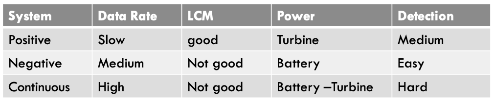
mud pulse telemetry Shortcomings
Transmission medium must be incompressible
Slow data transmission rates (1 to 3 bits/sec)
3. Advanced signal processing techniques are required to reduce the effects of distortion and noise within the telemetry band
Electromagnetic Telemetry
An electromagnetic wave is created, and it is transferred through the formation used when compressible drilling fluids are used & fore onshore mainly
Electromagnetic Telemetry characteristics
No continuous fluid column requirements
No LCM restrictions
Real-time use can be influenced by the vibration
Data transmission rate is slow, but possible while making a connection (save time)
Only batteries are the source of power (Usage life).
Two-way communication
Electromagnetic Telemetry advantages
No restriction on drilling fluid characteristics
Reduced survey/connection time
No moving parts
Factors effecting the signal of electromagnetic telemetry
Formation impedance (Higher than 500 ohms , or less than 10 ohms, not possible)
TVD (Signal loss due to pipe, solution Repeater)
MD (Signal loss due to pipe, solution Repeater)
Drilling fluid (OBM)
Casing effect (75 ft below casing shoe)
Batteries life time
wireline telemetry
Data can also be sent to the surface through a wire attached to the MWD tool (steering tools). With an attached wire, the drill-string cannot be rotated.
Today, wireline is used in conjunction with coiled tubing, where the drill string is a continuous length of metal pipe fed into the wellbore from a drum and cannot be rotated.
MWD tool operation
Surveys are taken when the tool is in stationary mode
Pump must be stopped for 30 to 60 second
Turn the pump back
Flow begins
Tool powered up
30 second warm up period
Running pulses start
Pulses are measured by the transducer and encoded by the surface computer
MWD surface processing
A transducer (or sensor) at the surface receives the pressure pulses and converts them to electrical signals.
Surface computers decode the electrical signals from the transducer and turn the digital information into engineering values and survey computations.
The data produced by the MWD tool is processed and used to provide information about the well. This information is used to make critical decisions about the drilling process, such as the well direction.
Monitors display data in real time on the drilling floor so that the driller can make well steering decisions
Gyroscopic Survey Tools
Provide an accurate means of surveying a borehole free from drill string and/or casing steel interference. Run (on wireline ) after a casing has been cemented as a verification survey to measure AHD.
→ must be centralised
Categories of Gyroscopic Survey Tools
Conventional Gyroscopic Survey Tools
North seeking Gyroscopic Tools
Inertial Grade Gyro (Inertial Navigation System)
Gyro while drilling (coming soon)
conventional gyroscopic tool
Spinning gyro determines azimuth using the difference between the orientation of the gyro (of known direction aka foresight) and the orientation of the case containing the gyro. Does not measure inclination independently.
conventional gyroscopic tool disadvantages
Drift: It is the rotation of outer gimbal due to earth rotation (time dependence)
Reference misalignment
Centralization
North seeking Gyroscopic Tools (Rate Gyro)
Based on the measurement of the horizontal component of the Earth rotation vector, which becomes smaller for increasing latitudes. It orients itself to true north, which eliminating the human error associated with Foresight and reduce the error due to drifting.
North seeking Gyroscopic Tools operation modes
Gyro-compassing Mode: the tool is held stationary, and the azimuth is calculated independently at each survey station by measuring the component of the Earth's rate of rotation vector in the horizontal plane.
Continuous Mode: At the start of the survey interval, the tool is referenced to True North by gyro-compassing. Following this, the tool is run continuously, with the tool's azimuthal change determined and its integration resulting in the actual azimuth.
North seeking Gyroscopic Tools limitations
Sensitive to motion
The maximum latitude of operation is approximately 80° N/S due to the reduction of the horizontal component of the Earth rotational vector, reducing the ability of tools to North seek.
For gyro compassing, the survey time might be longer, depends on survey interval.
Inertial Grade Gyro (Inertial Navigation System)
The system measures the change in direction of the platform and the distance it moves. It not only measures the inclination and direction of the well but it also determines the depth. Uses three rate gyros and three accelerometers mounted on a stabilized platform.
Inertial Grade Gyro (Inertial Navigation System) types
FINDS (Ferranti) → stable gimballed platform; accumulated error 1 ft/1000 ft; requires ~40 min surface initialization; limited to 13⅜" casing or larger
RIGS (Ring Laser) → strap-down system; usable in 7" casing/liners; accumulated error 2 ft/1000 ft; inclination limited to <45°; regular recalibration required
Gyroscopic Survey Advantage and Limitation
advantages:
Increased Accuracy : Improves the ellipse of uncertainty
Not Affected By Magnetic Fields: interference, e.g. batch setting conductors, casing string, drill-string, fish, formations, magnetized mud/cuttings or magnetic variations (daily, storms)
Resurveys: old wells, re-entries.
Surveying: in cased hole/tubing/Pipe , where magnetic survey tools can not be used
limitations:
very delicate and vulnerable in tough drilling environment
only run on wireline (or dropped) during drilling interruptions
Factors Influencing Survey Tool Selection
Target Size
Latitude of Well
Target Direction
Type of Drilling Installation
Rig Costs
Maximum Inclination Planned
Formation and Hole Conditions
Survey Depths
Open or Cased Hole
Survey Tool Selection Criteria
Application
Accuracy
Cost
Physical Constraints
Availability
Reliability
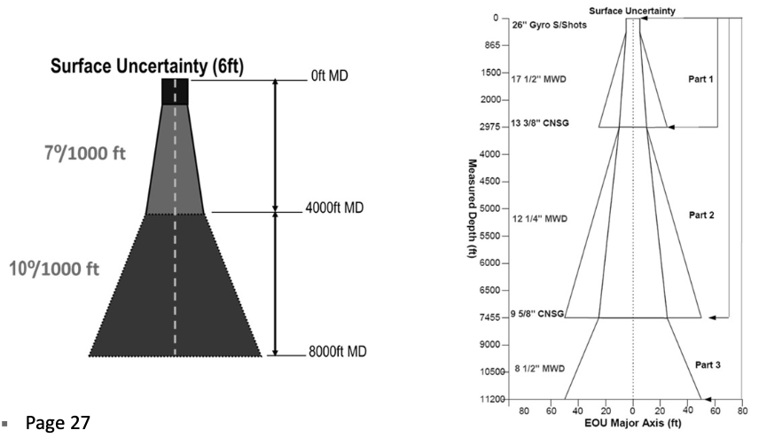
causes of wellbore position uncertainty
azimuth reading error
depth error
inclination error
helps constructing a cone of uncertainty around the actual
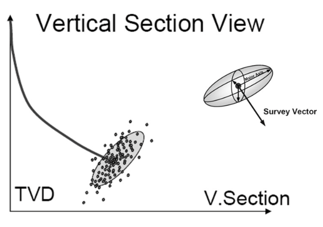
ellipsoid of uncertainty
inclination error create the high side
azimuth error creates the lateral side
measured depth error creates a 3rd component along the axis of the wellbore
EOU plan view
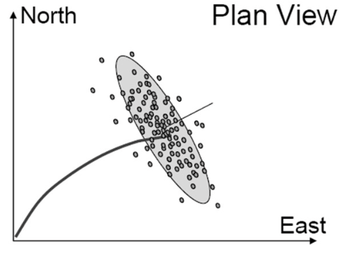
EOU vertical section view
survey accuracy reasons
geologic targets
regulation/ property lines
relief wells abandonment
prevent collision
anti-collision methods
Error System (Model): Wellbore position uncertainty (Error Method used)
Error Surface: Calculating dimension of error surfaces between Well-paths (Method to Measure Distance)
Warning Method: Criteria for reporting separation (Separation Factor)
Scan Method: Distance between well-paths (Planning and Execution)
error origins
Reference Error: Errors in altitude, coordinate system or the direction of Magnetic/True North
Misalignment Error and SAG
Relative Depth Error
Drill String Magnetization: Magnetic Interference
Drilling Fluid
Formations
Eroded steel from casing or drill-string
Inclination and Azimuth Errors – Tool sensor capability
Magnetic dip angle uncertainty
Magnetic field uncertainty
Accelerometer Bias error
Accelerometer Scale error
Magnetometer Bias error
Magnetometer Scale error
Cross-coupling/misalignment errors (Gyro tools)
in-field referencing
used to bypass the continuous change of magnetic storms via aeromagnetic & marine surveys to correct:
dip angle
magnetic field strength
declination
depth error sources
Pipe tally accuracy [+/- 2 to 3 ft]
HKLD sensor [+/- 1 to 2 ft]
Rig heave [+/- 1 to 2 ft]
Stretch due to weight [+ 30 ft]
Friction [+/- 5 ft]
Weight-on-Bit [+/- 3 ft]
Thermal expansion [+ 13 ft]
Pressure [ < 1 ft]
Buckling and Twisting [ < 1 ft]
sagging
Mechanical misalignment errors affecting directional survey measurements can be considered to be the difference between the orientation of the along-hole axis of the survey sensor and that of a line describing the geometric center of the well path.
factors effect SAG
mud weight
hole diameter
BHA diameter
stabiliser diameter & spacing
collar stiffness
formation stiffness
hole curvature
SAG correction
If it is less than 0.1° no correction applied
If it is greater than 0.1° , correction must be applied to correct the survey
If it is greater than 0.25⁰ , the BHA must be modified
error classification
random
systematic → generally expand to dominate the error envelope
correlated → continue to be carried across multiple runs of different sensors of the same type
uncorrelated → errors that don’t carry across different sensor runs or different tool runs
gross → usually caused by human faults or failures of instruments in use
global → affect every survey in every well in the same field
error models
Cone of Uncertainty Model
Walstrom Error Model
Wolff and De Wardt Error Model
Shell Extended Systematic Error Model [SESTEM]
Industry Steering Committee for Wellbore Survey Accuracy Error Model [ISCWSA]
cone of uncertainty
It consisted of a simple ratio with measured depth that applied over a range of inclinations.
wolff & de wards error model
considers relative depth, misalignment & inclination error, & compass reference & gyro compass
A set of values (coefficients) were chosen for each tool and the mathematical model produced an EOU
ISCWSA error model
Rely on mathematical descriptions of all error sources which allows for both geographic location, tool performance and all well shapes.
Assumptions and Limitations of the ISCWSA Model
Regular tool calibration
A maximum of 100 ft survey intervals.
Field QC checks, such as total magnetic field, gyro drifts, total gravity field and magnetic dip angle on each survey measurement.
The use of non-magnetic spacing for MWD surveys according to industry standard
For MWD, surveys taken in a magnetically clean environment away from casing and adjacent wells.
It does not cover gross blunder errors (Human errors).
ISCWSA process
Find all error sources affecting Measured Depth, Inclination, and Azimuth
Designate an error code to each error source
Each error source has a set of weighting functions, which are the equations that describe how the error source affects the actual survey measurements of measured depth, inclination, and azimuth.
Each error source also has a propagation mode which defines how it is correlated from survey to survey; this is used in summing up the errors.
For a particular survey tool, each error source has an error magnitude.
anti-collision methods
error system → wellbore position uncertainty
error surface → calculating dimension of error surfaces between well paths
Warning → criteria for reporting separation
Scan method → distance between well paths
Anti-collision well classification
single well → wellhead to wellhead distance > 12500m
Nearby well → any well that‘s not a single well
Anti collision scanning
global scan → the initial scan is made in the anti-collision planning process to scan through the entire database projector all nearby wells that fall within the user specified radius
Proximity scan → on all the wells that have been identified as nearby-well using the subsurface survey data associated with/ each nearby to calculate the distance from each well to the subject well along its length
Center to center distance
The distance between the subject well & the offset well, using:
horizontal plane
Normal plane
3D least distance
Horizontal plane
Use by spider. Proximity scanning steps horizontally down the subject well at specific intervals
Normal plane
Used by traveling cylinder. Proximity calculation steps down each offset well at the specified intervals to ensure that the proximity of the entire offset well is analyzed, and to ensure the scanning of any potential perpendicularly approaching wellbore. At each step down the offset well this method scans the subject well to determine where a plane normal to the subject well intersects the offset well at the respective scanning point.
3D least distance
Proximity scanning calculates the nearest distance to each offset well by stepping down the subject well at specified intervals to determine a plane that is normal to the offset well survey and which intersects the subject well at the interval point.
=> shortest distance between the subject & offset well from each of the respective subject well scanning points
Separation factor
The ratio of the CtC distance between wells & the sum of the radii of the EOU, between the subject & offset wells being scanned
SF = CtC distance/ EOC(SW) + EOC(OW)
SF>1 → completely separated ellipses = no overlap
SF=! → touching ellipses
SF<1 → overlapping ellispses
Oriented separation factor (pedal curve)
The ratio of the CtC separation between wells & the EOU separation, taking into account a fixed probability of collision as representing a SF of one
=> less conservative but more accurate
OSF = CtC distance/ OEOC(SW) + OEOC(OW)
OSF =< 5 → alert
OSF =< 1.5 → minor risk
OSF =< 1 → major risk
Clearance factor
CF = CtC distance/ CtC - (OEOC(SW)-OEOC(OW))
CF<1 → stop drilling, major risk
1<CF<1.25 → shut-in procedure
CF>1.5 → safe
Allowable deviation from plan (ADP)
The radial distance from the plan at any point to which the directional driller may be allowed to depart from the plan during the drilling process for the purposes of drilling efficiency w/o causing anti-collision
Min. Allowable separation (MAS)
The min. CtC distance between the subject & offset wells that s allowable w/o any violation of the drill ahead anti-collision rule = defines a safety zone
MAS = CtC - ADP
anti-collision reporting & scanning tools
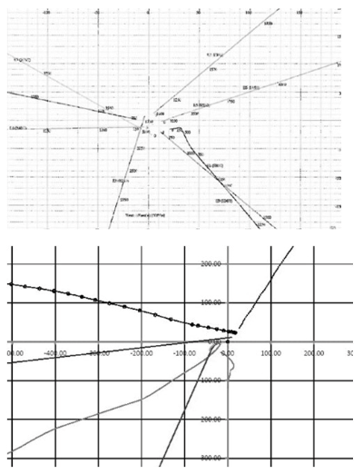
spider plot
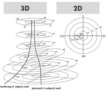
travel cylinder
ladder plot
separation factor plots
spider plot
is a scaled horizontal plan view of all wells that reconsidered potential collision risk to the new planned well
+basic & easy to understand
-misleading & difficult to understand
travel cylinder
a measure of how close adjacent wells are to the planned wells & a visualisation tool that involves imaging several concentric circles concentric to & normal to the planned wellbore (form imaginary cylinders down the wellbore)
center = subject well
around = dots on the flat plane
ladder plot
a graph of the separation to target wells against the measured depth of the planned well → determine which well to watch for at which depth
anti-collision analysis
performed during the planning phase
in case of anti-collision analysis: SF<1 and adjust well trajectory
risk assessment