Biomaterials | Final
1/102
There's no tags or description
Looks like no tags are added yet.
Name | Mastery | Learn | Test | Matching | Spaced | Call with Kai |
|---|
No analytics yet
Send a link to your students to track their progress
103 Terms
Protein Corona Challenges
Engineers often attach ligands to NPs to unlock specific receptors on cancer cells. Protein Corona can act like a thick, messy blanket.
Ex. Physical Obstruction: Proteins PHYSICALLY cover the ligands, preventing them from ever touching the target cell.
Strats for success: Protein-Resistant coatings like PEG to create a layer that minimizes protein sticking.
Surface Affecting Protein Adsorption
Surface Charge: Attracts or repels charged protein regions to surface charge.
Surface Roughness: Roughness traps proteins, promoting adsorption in valleys.
Hydrophobicity: Hydrophobic surfaces attract proteins, while hydrophilic surfaces repel them.
Steric Hindrance: LONG polymer chains create physical barriers that HINDER protein access to the surface; this method is commonly used with PEG modifications to reduce protein adsorption.
Surface Tension: EVERY material has a surface tension because atoms at the boundary have unfilled valence shells. TO REACH a lower-energy state, atoms at the boundary grabs molecules from its environment - aka adsorption (adsorption MINIMIZES surface energy = more stable state).
Adsorbate
a substance - typically gas, liquid, or dissolved solid - that adheres to the surface of another material (the adsorbent) during the process of adsorption; adsorbate includes ions, water, ions, and proteins; the body reacts to this COATED surface, not the pure biomaterial; controlling protein adsorption is key
Water Contact Angle Characterization
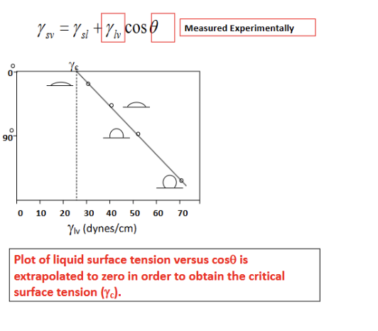
key method for quantifying the wettability and surface energy of a biomaterial; young’s equation; theta = contact angle measured through the liquid phase; graph = zisman plot = used to find a material’s critical surface tension (gamma_c); methodology for zisman: you measure the contact angle (theta) of SEVERAL different LIQUIDS with known surface tensions (gamma_lv) on the SAME solid surface; for the different liquids, as the surface tension of the liquid (gamma_lv) is lower, the liquid spreads more EASILY, and the contact angle (theta) is lower (meaning costheta increases toward 1); to find gamma_c, the data points are plotted as costheta vs gamma_lv. By extrapolating the line to where cos(theta)=1 (corresponding to theta = 0), you find critical surface tension; key: any liquid with a surface tension lower than or equal to gamma_c will spontaneously spread across and completely wet that specific solid surface; exp steps for accurate data: surface prep (contaminants (like oils or dust) drastically alter surface energy, so the sample must be ultra-clean), droplet placement (a goniometer uses a precision syringe to dispense a microliter-scale droplet to ensure gravity doesn't distort the droplet shape), angle measurement (high-resolution cameras capture the profile of the drop where it meets the solid), data analysis (analyze contact angle measurements; determine surface wettability and critical surface tension).
Biomaterial Surface Characterization Techniques
AFM, SEM, XPS, Contact Angle Measurement, FTIR, Ellipsometry
Physical & Morphological Characterization (Atomic Force Microscopy (AFM) + SEM);
Uses a physical probe to "feel" the surface. It provides a 3D topographic map with nanometer resolution.
Surface topography at the nanoscale; ex. evaluating roughness of implant coatings
Scanning Electron Microscopy (SEM): Uses an electron beam to create high-resolution images. It is excellent for seeing the architecture of porous scaffolds or the integrity of a coating.
High-resolution imaging of surface structure; ex. visualizing scaffold PORE structures.
Chemical & Elemental Analysis (XPS + FTIR)
X-ray Photoelectron Spectroscopy (XPS/ESCA): Bombards the surface with X-rays to measure the KE of EMITTED electrons. This identifies the ELEMENTAL composition (e.g., "Is there Carbon here?") and the chemical state (e.g., "Is that Carbon part of a methyl group or a carboxyl group?").
Elemental composition and chemical states; ex. determining surface functional groups after coating.
FTIR: Uses INFRARED light to identify chemical BONDS based on how they VIBRATE. It’s a "fingerprinting" tool for identifying functional groups on hydrogels or polymers.
Surface chemistry and molecular interactions; ex. detecting functionalization of hydrogels (functionalization of a hydrogel refers to the chemical modification of the polymer network to add specific “functional groups” that give the gel new properties; plain hydrogels like in contact lenses are often inert buckets of water; by functionalizing them, we make them smart; drug delivery: attaching a tether molecule that holds a drug and only releases when the pH changes; cell adhesion: adding RGD peptides so that cells can grab onto the gel and grow; if you functionalized a gel with a carboxyl group, you would look for a peak on the FTIR spectrum that wasn’t there before; if the peak appears at the correct frequency, functionalization is confirmed).
Surface Energy (Contact Angle Measurement)
Contact Angle Measurement: Quantifies wettability (hydrophobicity vs. hydrophilicity). As we discussed, a lower contact angle indicates better spreading and higher surface energy.
=> LOWER contact angle = higher surface energy because: High Surface Energy: The surface atoms are very "unhappy" and have a strong desire to bond with something to reduce that tension. Low Surface Energy: The surface is relatively stable and "satisfied" (like a non-stick Teflon coating), feeling very little pull to interact with outside molecules.
When Surface Energy is High: The solid has a massive "appetite" to bond. Its adhesive pull on the liquid is much stronger than the liquid's internal cohesive pull. The surface effectively yanks the liquid down and flattens it out. Result: The droplet spreads flat => Low Contact Angle.
When Surface Energy is Low: The solid doesn't care much about the liquid. The liquid's internal cohesive forces win the tug-of-war, keeping the molecules tightly packed together. The droplet stays in a bead => High Contact Angle.
Wettability and hydrophobicity; ex. assessing biocompatibility of polymer coatings
Thickness Characterization (Ellipsometry)
Ellipsometry: Measures changes in the POLARIZATION of light REFLECTING off a surface. This is the gold standard for measuring the thickness of THIN films (like a protein layer or a drug-eluting coating) and their refractive index.
Thin film thickness and refractive index; measuring deposition of biomaterial coatings (deposition = process of applying a thin layer of material/coating onto a substrate; measuring this deposition ensures that the coating is exactly where it should be, at right thickness and with right consistency).
Four Pillars of Surface Modification
Thin: It should be a surface-level change only. If it's too thick, you might accidentally change how the entire device bends or supports weight.
Resistant: It must stay attached. In the harsh environment of the body (in vivo), many coatings tend to peel off (delamination).
Simple: For a medical device to be mass-produced (commercialization), the process can't be overly complex or prone to error.
Discourage Rearrangement: Surface atoms often try to "flip" or hide to reduce energy. A good modification stays stable over time.
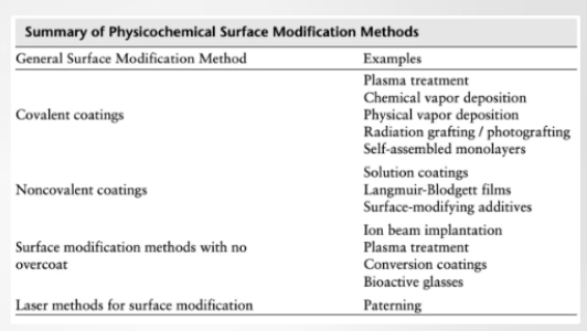
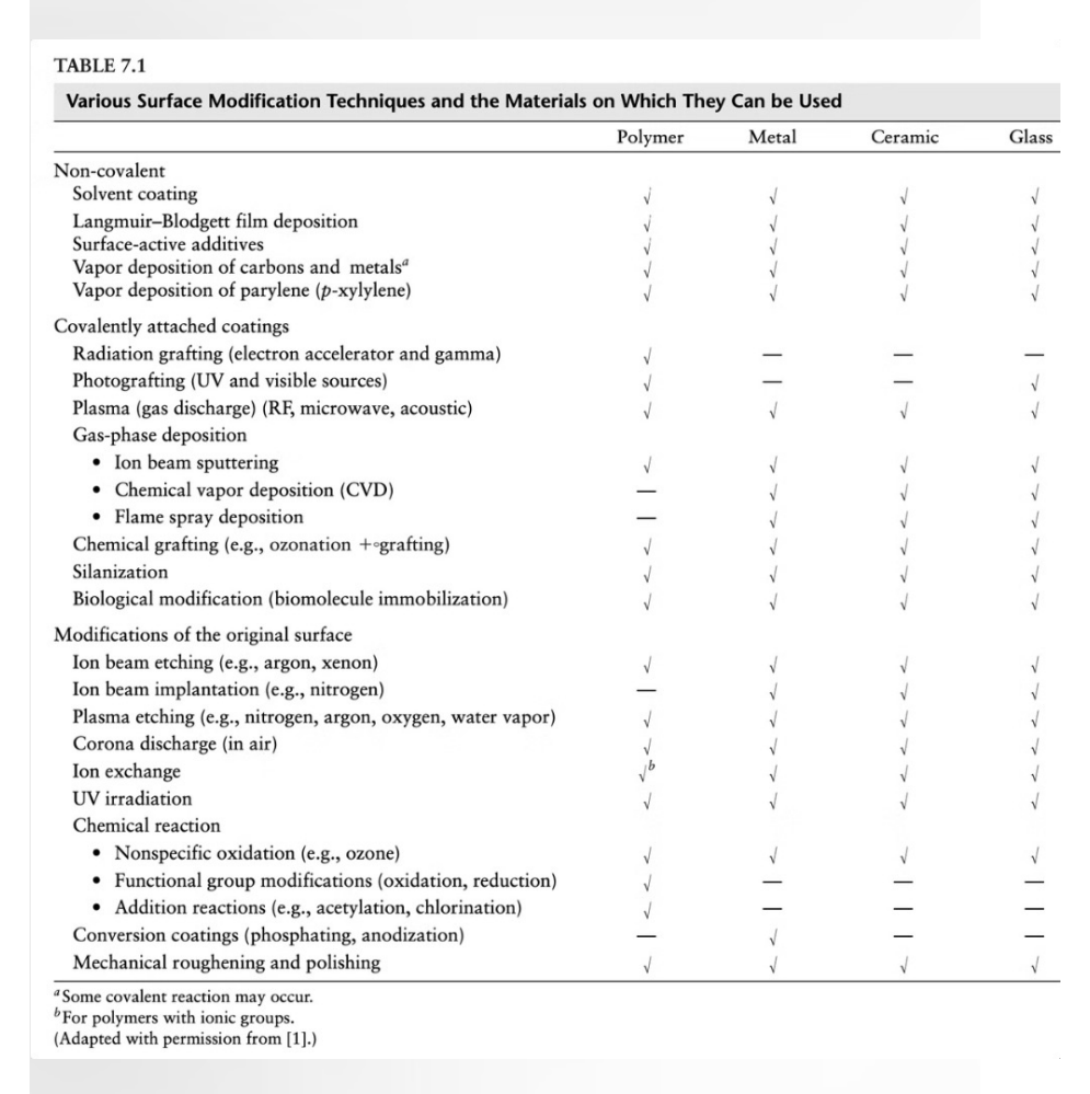
General Surface Modification Methods and Examples:
Covalent bonding (plasma, CVD, PVD, radiation grafting/photografting, SAMs) (using STRONG CHEMICAL bonds to LOCK the modification into place): Plasma Treatment: Using ionized gas to "blast" the surface, creating reactive sites for NEW molecules to bond. CVD & PVD (Chemical/Physical Vapor Deposition): Transforming a material into a vapor and letting it condense as a solid film. Self-Assembled Monolayers (SAMs): Molecules that spontaneously organize themselves into a single, perfectly ordered layer.
Noncovalent bonding (physical interaction) (solution coatings, LB films, surface-modifying additives) (rely on weaker forces like hydrophobic interactions or adsorption RATHER than chemical bonds): Solution Coatings: Simply dipping the device into a polymer solution (dip-coating). Langmuir-Blodgett films: A technique to transfer ultra-thin layers from a LIQUID surface to a SOLID substrate.
Methods with No Overcoat (Modification without "Adding") (instead of adding a new layer, these methods change the existing atoms of the material) (ion beam implantation, plasma treatment, conversion coatings, bioactive glasses): Ion Beam Implantation: High-energy ions are shot into the surface to change its HARDNESS or CHEMISTRY. Conversion Coatings: A chemical reaction TRANSFORMS the top layer of metal into a protective oxide or phosphate layer.
Laser Methods (patterning): Using a laser to ETCH micro-scale or nano-scale textures. This can be used to "GUIDE" cells to grow in a specific direction or to make a surface naturally antibacterial.
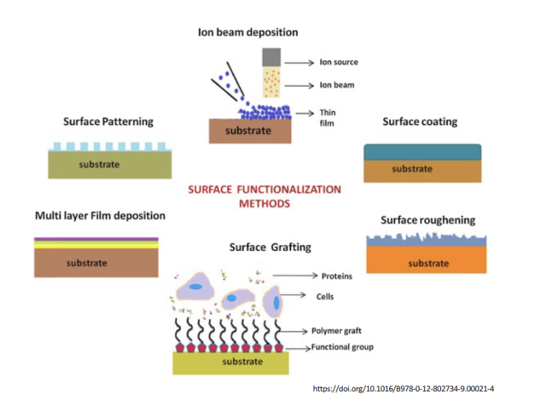
Visual Surface Modification Techniques
1. Additive Methods (Adding a Layer)
These methods build a new material on top of the substrate.
Ion Beam Deposition: An ion source directs a beam of particles toward the surface. As shown, this creates a thin film. This is often used to deposit very hard or biocompatible metallic/ceramic coatings.
Surface Coating: This is a general term for applying a uniform layer (like a polymer or lubricant) over the substrate. This changes the surface energy and chemistry of the device.
Multi-layer Film Deposition: Often called "Layer-by-Layer" (LbL) assembly. It involves depositing alternating layers of oppositely charged materials. This is excellent for creating "reservoir" coatings that can release drugs over time.
2. Subtractive or Textural Methods (Changing the Shape)
These focus on the topography and roughness mentioned in your characterization table.
Surface Patterning: Uses techniques like photolithography or laser etching to create organized geometric structures (like the "pillars" shown). This is used to guide cell growth or create "lotus-leaf" effects for extreme hydrophobicity.
Surface Roughening: Increasing the "nooks and crannies" on a surface. In orthopedic implants (like titanium hips), a rougher surface allows bone cells to physically "interlock" with the metal, a process called osseointegration.
3. Chemical Linking: Surface Grafting
This is the most sophisticated form of functionalization shown here.
The Structure: Functional groups (the red shapes) are attached to the substrate. Long polymer chains ("grafts") are then grown from these groups.
The "Smart" Interface: These polymer grafts act like a forest that can either:
Attract: Catch specific proteins or cells (as labeled in the diagram).
Repel: Create a "hydration layer" that prevents unwanted protein adsorption (the Vroman effect we saw earlier).
Plasma Charge Treatment
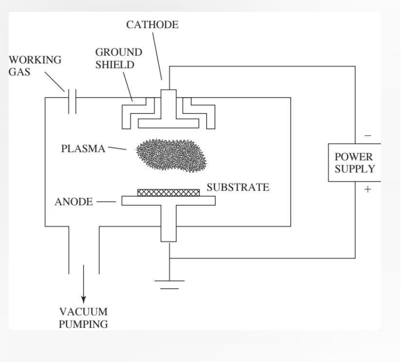
Plasma treatment is a powerful surface modification technique used to change the chemical AND physical properties of a material (like a polymer or a vascular graft) without affecting its bulk mechanical strength.
Process:
1. Vacuum & Gas: A gas (like N2 or Ar) is introduced into a vacuum chamber.
2. Ionization: A high-voltage power supply creates an electric field BETWEEN an Anode (has a negative potential) and a Cathode (where your sample is placed; CATHODE = the sample). This field STRIPS ELECTRONS from the GAS atoms, creating a "PLASMA" of ions, electrons, and radicals.
3. Bombardment: These high-energy particles COLLIDE with the SURFACE of your sample.
The result: The plasma "BLASTS" the surface at an atomic level. This can ETCH the surface to increase roughness or add new chemical functional groups (like hydroxyl or amine groups), which drastically changes the material's hydrophobicity and surface charge.
Traverse Gas: Gas moving across (or through) a system or space in a lateral or crosswise direction. Traverse Gas means a gas that flows across a section rather than along the main direction. Electrons: Traverse gas, collide to form ions/radicals.
More Clarification: Chemical Bond Breaking: The energetic particles also: break existing bonds (like C-H or C-C in polymers) and leave behind “dangling bonds” (highly reactive sites). Functionalization (adding new chemical groups): Depending on the plasma gas used (oxygen, nitrogen, ammonia, etc.), new groups get attached: oxygen plasma => -OH (hydroxyl), -COOH; nitrogen plasma => -NH2 (amine). The surface chemistry is completely altered without affecting the bulk material. Why does this change hydrophobicity: Hydrophobicity is governed by surface chemistry and structure. Before plasma: Surface may be nonpolar (e.g. hydrocarbons). Water beads up => hydrophobic. After plasma: Polar groups (-OH, -NH2) are introduced. These form HYDROGEN BONDS with water. This ties directly to surface energy. This TIES directly to surface energy (higher surface energy => more wettable [hydrophilic]; lower surface energy => more hydrophobic). Plasma increases surface energy => water spreads instead of beads.
Clarification: Higher surface energy = more wettable since high surface energy (solid) => strongly “pulls” on the liquid => liquid spreads; low surface energy (solid) => weak interaction => liquid beads up.
Continued from More Clarification: Why Surface Charge Changes: Those new functional groups can: gain or lose protons (depending on pH), create localized charges. Example: -COOH can become negatively charged (-COO^-). -NH2 can become positively charged (-NH3+). Result: The surface now interacts differently with proteins, cells, adhesives, and liquids.
![<p>Plasma treatment is a powerful surface modification technique used to change the chemical AND physical properties of a material (like a polymer or a vascular graft) without affecting its bulk mechanical strength.</p><p>Process:</p><p>1. <strong>Vacuum & Gas:</strong> A gas (like N2 or Ar) is introduced into a vacuum chamber.</p><p>2. <strong>Ionization:</strong> A high-voltage power supply creates an electric field BETWEEN an <strong>Anode</strong> (has a negative potential) and a <strong>Cathode</strong> (where your sample is placed; CATHODE = the sample). This field STRIPS ELECTRONS from the GAS atoms, creating a <strong>"PLASMA" of ions, electrons, and radicals.</strong></p><p>3. <strong>Bombardment:</strong> These high-energy particles COLLIDE with the SURFACE of your sample.</p><p>The result: The plasma "BLASTS" the surface at an atomic level. This can ETCH the surface to increase <strong>roughness</strong> or add new chemical functional groups (like hydroxyl or amine groups), which drastically changes the material's <strong>hydrophobicity</strong> and <strong>surface charge</strong>.</p><p></p><p>Traverse Gas: Gas moving across (or through) a system or space in a lateral or crosswise direction. Traverse Gas means a gas that flows across a section rather than along the main direction. Electrons: Traverse gas, collide to form ions/radicals.</p><p>More Clarification: Chemical Bond Breaking: The energetic particles also: break existing bonds (like C-H or C-C in polymers) and leave behind “dangling bonds” (highly reactive sites). Functionalization (adding new chemical groups): <strong>Depending on the plasma gas used (oxygen, nitrogen, ammonia, etc.), new groups get attached: oxygen plasma => -OH (hydroxyl), -COOH; nitrogen plasma => -NH2 (amine). </strong>The surface chemistry is completely altered without affecting the bulk material. Why does this change hydrophobicity: Hydrophobicity is governed by surface chemistry and structure. Before plasma: Surface may be nonpolar (e.g. hydrocarbons). Water beads up => hydrophobic. After plasma: Polar groups (-OH, -NH2) are introduced. These form HYDROGEN BONDS with water. This ties directly to surface energy. This TIES directly to surface energy (higher surface energy => more wettable [hydrophilic]; lower surface energy => more hydrophobic). Plasma increases surface energy => water spreads instead of beads. </p><p>Clarification: Higher surface energy = more wettable since high surface energy (solid) => strongly “pulls” on the liquid => liquid spreads; low surface energy (solid) => weak interaction => liquid beads up. </p><p>Continued from More Clarification: Why Surface Charge Changes: Those new functional groups can: gain or lose protons (depending on pH), create localized charges. Example: -COOH can become negatively charged (-COO^-). -NH2 can become positively charged (-NH3+). Result: The surface now interacts differently with proteins, cells, adhesives, and liquids. </p><p></p>](https://assets.knowt.com/user-attachments/6a775bbf-11c3-459f-b0b1-7877aac0faaf.png)
Plasma Treatment Mechanisms
Plasma treatment modifies a surface through three primary physical and chemical actions:
Ablation/Etching: Energetic species in the plasma SLAM into the surface, causing PHYSICAL etching. This INCREASES surface roughness, which can trap proteins or improve mechanical interlocking for coatings.
Cleaning/Functionalization: The process removes organic contaminants and adds NEW chemical groups like hydroxyl (-OH) or amine (-NH2) groups. This significantly INCREASES surface energy and can change a surface from hydrophobic to HYDROPHILIC.
Adds hydroxyl or anime groups.
Deposition: Radicals in the PLASMA can polymerize gas molecules to create a NEW THIN-FILM layer directly on the sample.
Advantages & Disadvantages of Plasma Treatment
Advantages: Conformal (the plasma flows around complex 3D shapes, like the coils of a stent or the threads of a bone screw, treating the entire surface evenly), Void-free (applied at the atomic level, ensuring a perfect seal), Easily Prepared, Sterile (Plasma discharge naturally creates UV light, which is a powerful disinfectant that breaks down the molecular bonds of pathogens)
Disadvantages: Ill-defined chemistry (plasma is a “chaotic soup.” while you might want to add just hydroxyl groups, you often end up with a mix of different chemical bonds that are hard to map perfectly), Expensive equipment, Pore uniformity (the difficulty of treating the INSIDE of a porous material like a scaffold for bone growth as effectively as outside), Contamination (if the vacuum chamber ISN’T perfectly clean)
Chemical Vapor Deposition (CVD)
Precursor Gases: A gas mixture (often hydrocarbons) is released into a chamber containing a heated substrate. Thermal Decomposition: The high temperature causes the gas molecules to decompose or react when they hit the heated sample holder. Solid Film: The result of this reaction is a solid, ultra-thin coating (like pyrolytic carbon or ceramics) that deposits evenly across the substrate.
Chemical vapor deposition (CVD) is a technique where a mixture of gases is exposed to a sample at a high temperature. This environment causes chemical reactions that decompose the precursor gases, resulting in the deposition of a coating on the surface. The effect of protein adsorption likely depend on the chemistry of the deposited coating. If CVD was used to deposit a hydrophobic carbon coating, it could increase protein adsorption. However, if CVD was used to deposit a hydrophilic coating, it could decrease protein adsorption.
Equipment: Plasma assists to reduce reaction temperature. Standard CVD often requires very high temperatures (hundreds of degrees Celsius), which would melt many polymers or hydrogels. By adding plasma to the mix, the high-energy electrons provide the ENERGY needed to break the gas bonds, allowing the coating to form at much lower temperatures. This makes it possible to coat heat-sensitive medical devices.
Application: Deposits pyrolytic carbon coatings. Gases are hydrocarbons undergoing pyrolysis (chemical process where a material is heated to high temperatures in the absence [or near absence] of oxygen, causing it to break down into simpler substances).
![<p><strong>Precursor Gases:</strong> A gas mixture (often hydrocarbons) is released into a chamber containing a heated substrate. <strong>Thermal Decomposition:</strong> The high temperature causes the gas molecules to decompose or react when they hit the heated sample holder. <strong>Solid Film:</strong> The result of this reaction is a solid, ultra-thin coating (like pyrolytic carbon or ceramics) that deposits evenly across the substrate.</p><p><span>Chemical vapor deposition (CVD) is a technique where a mixture of gases is exposed to a sample at a high temperature. This environment causes chemical reactions that decompose the precursor gases, resulting in the deposition of a coating on the surface. The effect of protein adsorption likely depend on the chemistry of the deposited coating. If CVD was used to deposit a hydrophobic carbon coating, it could increase protein adsorption. However, if CVD was used to deposit a hydrophilic coating, it could decrease protein adsorption.</span></p><p><span>Equipment: </span><strong>Plasma assists to reduce reaction temperature</strong>. Standard CVD often requires very high temperatures (hundreds of degrees Celsius), which would melt many polymers or hydrogels. By adding plasma to the mix, the high-energy electrons provide the ENERGY needed to break the gas bonds, allowing the coating to form at much <strong>lower temperatures</strong>. This makes it possible to coat <strong>heat-sensitive medical devices.</strong></p><p>Application: Deposits pyrolytic carbon coatings. Gases are hydrocarbons undergoing pyrolysis (chemical process where a material is heated to high temperatures in the absence [or near absence] of oxygen, causing it to break down into simpler substances). </p>](https://assets.knowt.com/user-attachments/45564bb4-c8b7-4d51-9db3-969a1a38c7bc.png)
Plasma Assisted Physical Vapor Deposition
The PAPVD / Sputtering Process
Think of this as a high-tech "billiards" game at the atomic level:
The TARGET (Cathode): You start with a solid block of the MATERIAL you want to deposit (like Titanium or Gold). This is the Cathode and maintains a NEGATIVE potential.
Ion Bombardment: Inert gas (usually Argon) is IONIZED into a plasma. These Ar+ ions are attracted to the negative TARGET and SLAM into it with massive energy.
Ejection & Deposition: The impact knocks individual atoms off the target. These atoms fly through the vacuum and land on your Substrate (your medical device), forming a dense, high-adhesion film.
Plasma Environment Creation: Created using inert gases like argon to generate high-energy species. Plasma-Target Interaction: High-energy species collide with a TARGET, generating ions and electrons for efficient sputtering. Enhanced Energy Transfer: The target maintains a negative potential relative to the substrate, enhancing energy transfer!
Clarification: Target: (The Source):
Identity: This is the material you want to turn into a coating (e.g. a solid block of titanium, gold, or a ceramic). Acts like a cathode (a negative electrode). It gets "blasted" by argon ions from the plasma. These ions knock atoms off the target like a cue ball hitting a pack of billiard balls.
The Substrate (The "Destination"): This is the actual medical device or sample you are trying to coat (e.g., your orthopedic hip stem, a drug-delivery nanoparticle, or a heart valve). It is usually grounded or held at a different potential than the target to encourage the atoms to land on it. It sits there and "collects" the atoms flying off the target. Over time, these atoms build up to form the thin film.
Atoms are deposited on the substrate surface with better control and higher deposition rates. Results in DENSER films at LOWER temperatures with enhanced adhesion properties.
Radiation & Photo-Grafting
Radiation Grafting: Substrate exposed to HIGH-ENERGY radiation. Reactive species form at the surface, COVALENTLY bonding the coating. Often binds hydrogels.
Uses high-energy ionizing RADIATION (such as gamma rays or electron beams) to initiate the process. Mechanism: The radiation hits the substrate, knocking off atoms or breaking bonds to create reactive species (usually free radicals) on the surface. Result: These surface radicals react with monomers in the surrounding environment, creating a strong covalent bond between the substrate and the new coating. Common Use: It is frequently used to bind hydrogels to medical devices, improving biocompatibility and lubricity.
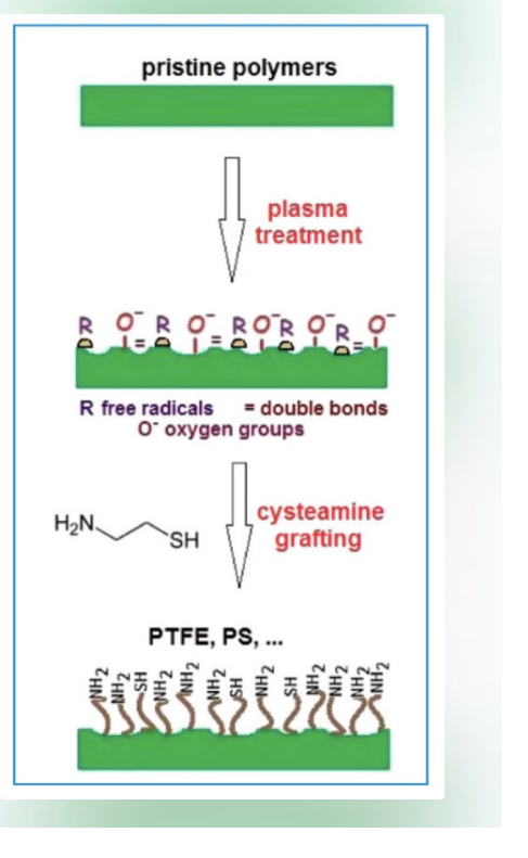
Photografting: Radiation is UV or visible light. Photoresponsive chemical moieties facilitate modification. Uses phenyl azide or benzophenone chemistry.
Similar to radiation grafting, but it uses lower-energy light (UV or visible) and specific chemical additives. Mechanism: Because UV light is less energetic than gamma rays, it often requires photoresponsive chemical moieties (initiators) (specific parts or functional groups within a larger molecule that have their own chemical identity or role). Chemistry: It typically utilizes phenyl azide or benzophenone chemistry. When these chemicals are exposed to light, they become highly reactive and "anchor" the desired coating to the surface.
Diagram: The diagram on the right illustrates a specific multi-step workflow often used for inert polymers like PTFE (Teflon) or PS (Polystyrene): Pristine Polymers: The starting material is chemically inert and "slick," making it hard for other materials to stick to it. Plasma Treatment: The polymer is exposed to plasma (ionized gas). This "activates" the surface by creating: R (Free Radicals) and Double Bonds (=). O⁻ (Oxygen groups). This creates a reactive "landing pad" on an otherwise non-reactive surface. Cysteamine Grafting: A molecule called cysteamine ($H_2N-CH_2-CH_2-SH$) is introduced. The sulfur ($SH$) or amine groups react with the plasma-activated sites. That is a very sharp observation! Technically, the process shown in the diagram is neither radiation nor photografting—it represents Plasma-Induced Grafting.
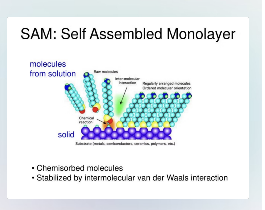
Self-Assembled Monolayers (SAMs)
Head Group: Terminal functional polar group that determines surface properties.
Alkyl Chain: Long hydrocarbon chain providing structural stability.
Attachment Group: Chemical group that binds to the substrate surface (e.g. Silanes react with amine or hydroxyl groups).
Preferred Substrates Exothermic reaction with the substrate. Materials with hydroxyl groups are preferred (.e.g. glass, metal oxide).
Self-assembled monolayers form a hierarchical structure where each component plays a crucial role in the overall functionality.
One surface modification technique used to control protein adsorption is the use of self assembled monolayers (SAMs). SAMs are formed when specially designed amphiphilic molecules spontaneously organize into a monolayer on a biomaterial surface. Each molecule contains an attachment group that forms a strong, covalent bond with substrate, a long hydrophobic (alkyl) chain, and a functional (polar) head group. The mechanism of SAM formation is driven by a strong, exothermic reaction between the attachment group and the surface, which anchors the molecules in place. As more molecules assemble, van der Waals interactions between the alkyl chains promote tight packing, creating a stable, highly ordered monolayer. SAMs control protein adsorption primarily through their functional head groups. By tailoring these groups, the surface can be made more hydrophilic or chemically inert, which reduces proteins binding, or more hydrophobic, which can increase protein adsorption. Additionally, the formation of a smooth, uniform layer minimizes surface roughness, which can further decrease protein adsorption.
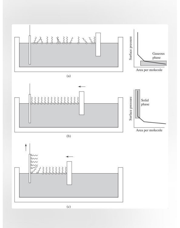
Langmuir-Blodgett Films
Amphiphilic Molecules Coating: molecules have a hydrophilic head and a hydrophobic tail. They are transferred to a surface.
Compression: A barrier COMPRESSES the coating until molecules stand on end. Area per molecule reaches a minimum (critical area).
Deposition: Maintain surface pressure as material is removed. A homogenous, orientated coating is deposited.
A technique used to create ultra-thin, highly organized coatings—often just one molecule thick (a monolayer)—on a solid surface.
Chat: The process starts with amphiphilic molecules that have a hydrophilic (water-loving) head and a hydrophobic (water-fearing) tail). They are spread onto a liquid surface (usually water). Naturally, the heads sit in the water while the tails point up into the air. At this stage, they are far apart, acting like a 2D gas. Compression: A movable barrier slowly slides across the surface, pushing the molecules together. As the area DECREASES, the molecules are forced to stand upright and pack tightly together. This transitions the film from a "gas" phase to a "liquid" phase, and finally to a solid crystalline-like phase. Deposition: Once the molecules are perfectly packed, a solid substrate (like a glass slide or silicon wafer) is dipped into or pulled out of the liquid. Because the molecules are held under constant pressure, they transfer onto the solid surface in a homogeneous, oriented fashion. This allows you to build a coating one layer at a time with extreme precision. Langmuir-Blodgett films are held together by weak van der Waals interactions and are not chemically bonded to the surface. Makes Langmuir-Blodgett films more prone to rearrangement under physiological conditions
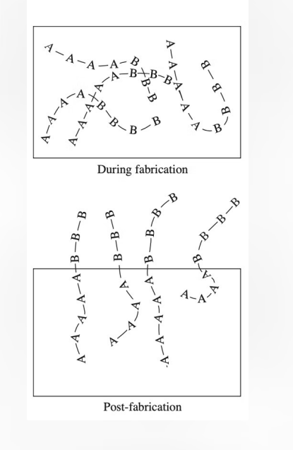
Surface-Modifying Additives (SMAs)
Surface-modifying additives create specialized surface characteristics through SPONTANEOUS migration of atoms or molecules to the material surface, driven by the REDUCTION OF FREE ENERGY.
Mechanism: Spontaneous surface migration of atoms/molecules. Effectiveness depends on surface tension and mobility. Integrated during material formation, not post-fabrication.
Material Applications: Metals: Copper in gold alloys, chromium on steel for corrosion resistance. Ceramics: Limited applications due to LOW atomic mobility. Polymers: Block copolymers with compatible (A) and incompatible (B) blocks.
Design Principles: Block A provides anchoring to base material. Block B determines surface properties. Surface tension drives reorganization.
The effectiveness of SMAs depends on the careful balance between surface tension, molecular mobility, and environmental conditions, making material selection and design crucial for successful implementation.
Essentially, if a specific molecule or atom is "uncomfortable" inside the bulk material (high energy), it will spontaneously migrate to the surface to lower the overall energy of the system. Think of it like oil separating from water and rising to the top.
Design Principles (The A-B Strategy): The diagram on the right shows how this works in polymers using Block Copolymers: Block A (The Anchor): This part of the molecule is compatible with the bulk material. It stays "tucked in" to keep the ADDITIVE firmly anchored so it doesn't just rub off. Block B (The Functional Surface): This part is INCOMPATABILE with the bulk but provides the desired surface properties (like being water-repellent or protein-resistant). It "pokes out" at the surface.
Metals: Atoms like chromium in steel migrate to the surface to form a protective oxide layer (making it "stainless").
Polymers: Uses the A-B block copolymer method shown in the diagram.
Ceramics: Rare, because atoms in ceramics don't move around (low mobility) easily once they are formed.
Integrated vs. Post-Fabrication: SMAs are mixed in at the start. Radiation/Photo-grafting and LB films are "top-down" treatments done to a finished part. Self-Healing: If an SMA surface is scratched, more additives from the bulk can sometimes migrate up to "heal" the gap. In contrast, a grafted coating, once scratched, is gone forever.
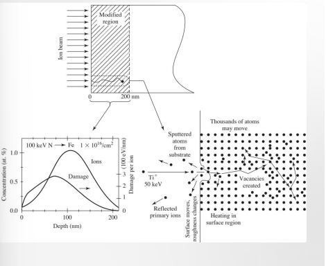
Ion Beam Implantation
Accelerated high-energy ions directed at the surface. Used for METALS and CERAMICS. Ions penetrate INTO the surface.
Results: Vacancies and interstitials are formed. Atoms are ejected. Crystal structure changes.
Chat: In this method, ions (charged atoms) are accelerated to very high velocities using an electric field and fired directly at the surface of a material. Penetration: Unlike plasma treatment, which mostly affects the very top layer of atoms, these high-energy ions physically blast their way into the substrate, typically reaching depths of 10 to 1000 nanometers. Collision Cascade: As shown in the "Thousands of atoms may move" part of your diagram, a single incoming ion can displace hundreds of substrate atoms, creating a "collision cascade." Vacancies & Interstitials: Ions knock atoms out of their regular spots in the crystal lattice (creating vacancies) and wedge themselves into the gaps (becoming interstitials). Sputtering: Some atoms from the original substrate are actually ejected (sputtered) OFF the surface entirely. Crystal Structure Changes: The heavy bombardment can turn a crystalline surface into an amorphous (glass-like) layer.
Ion beam implantation is a technique in which accelerated high-energy ions are directed at the surface of a biomaterial. As the ions interact with the material surface, they generate cascades of vacancies and interstitials, with atoms being displaced multiple times before coming to rest in new positions. In some cases, atoms may also be sputtered from the surface due to the high energy of the incoming ions. These structural changes can increase overall surface roughness, enhancing protein adsorption.
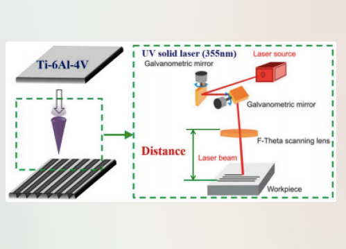
Laser Methods for Surface Modification
High Energy & Versatility: By focusing high-powered light onto a specific spot, lasers can induce several different physical and chemical changes: Annealing: Heating the surface to RELIEVE internal stresses or change the crystal structure without melting the whole part. Etching: Physically REMOVING material to create micro-patterns or "ROUGHNESS" (shown in the Ti-6Al-4V diagram on the left). Film Deposition & Polymerization: Using LIGHT to trigger chemical reactions that "cure" a coating or grow a thin film on the surface.
High Energy: Focusing high-powered light at the sample. Facilitates annealing, etching, film deposition, and polymerization.
Atmospheric Conditions: Treatment can occur at atmospheric conditions. Have specific control of reaction time and location.
Case Study: Chemical Surface Etching of Biomaterials
A titanium dental implant required enhanced surface roughness for better osseointegration. Chemical etching using dual acid treatment (HCl/H2SO4) created controlled micro-scale surface features. This is a "subtractive" method, where material is strategically removed to create a specific texture.
The primary goal for any bone-contacting implant (like a dental screw or a hip replacement) is osseointegration—the structural and functional connection between living bone and the surface of a LOAD-BEARING implant. Problem: Smooth titanium surfaces don't provide enough "grip" for bone cells (osteoblasts) to anchor to. Solution: Create a microporous structure that increases surface area and allows bone to grow into the pits and valleys.
Results/Impact: Surface roughness increased from 0.5μm to 2.1μm. Clinical studies showed 40% improvement in bone attachment after 8 weeks compared to non-etched surfaces. Now standard practice in implant manufacturing.
Unlike laser etching (which uses heat to melt/vaporize), acid etching uses a chemical reaction to dissolve the metal at grain boundaries and specific sites, creating a uniform, "spongy" texture.
Biological Surface Modification
This involves attaching living or bioactive components to a material to give it "intelligence" or better compatibility with the human body.
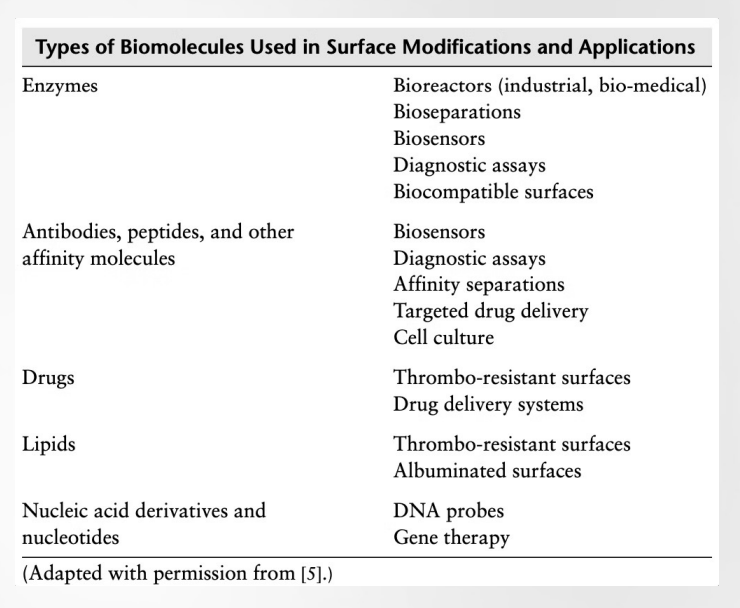
Attachment of biologically active molecules (chosen because they interact with specific targets, like receptors on a cell or specific proteins in the blood) (instead of just changing the texture, you are giving the surface a specific biological function) to a substrate. Molecules interact with specific targets on cells or tissues. Molecule must remain attached and maintain biological activity. Pay attention to the orientation and rotation of molecules. Polymeric Substrates: Most work centers on polymeric substrates. Attachment is successful on soluble, solid (implants), porous polymers (scaffolds for tissue engineering), and hydrogels (soft, water-rich materials that mimic natural tissue).
Exs:
Enzymes: application: biosensors: They catalyze reactions (e.g., a glucose sensor uses enzymes to "read" blood sugar).
Antibodies: application: targeted drug delivery: they act like GPS, finding specific diseased cells and ignoring healthy ones.
Drugs: Thrombo-resistant surfaces. Heparin-coated surfaces prevent blood clots from forming on heart valves.
Lipids: Albuminated (something that has albumin in it or is mixed with it) surfaces: creating a "fat-like" layer to make a surface more biocompatible.
Nucleic Acids: applications: Gene Therapy / DNA Probes: using DNA/RNA sequences to detect viruses or deliver genetic instructions.
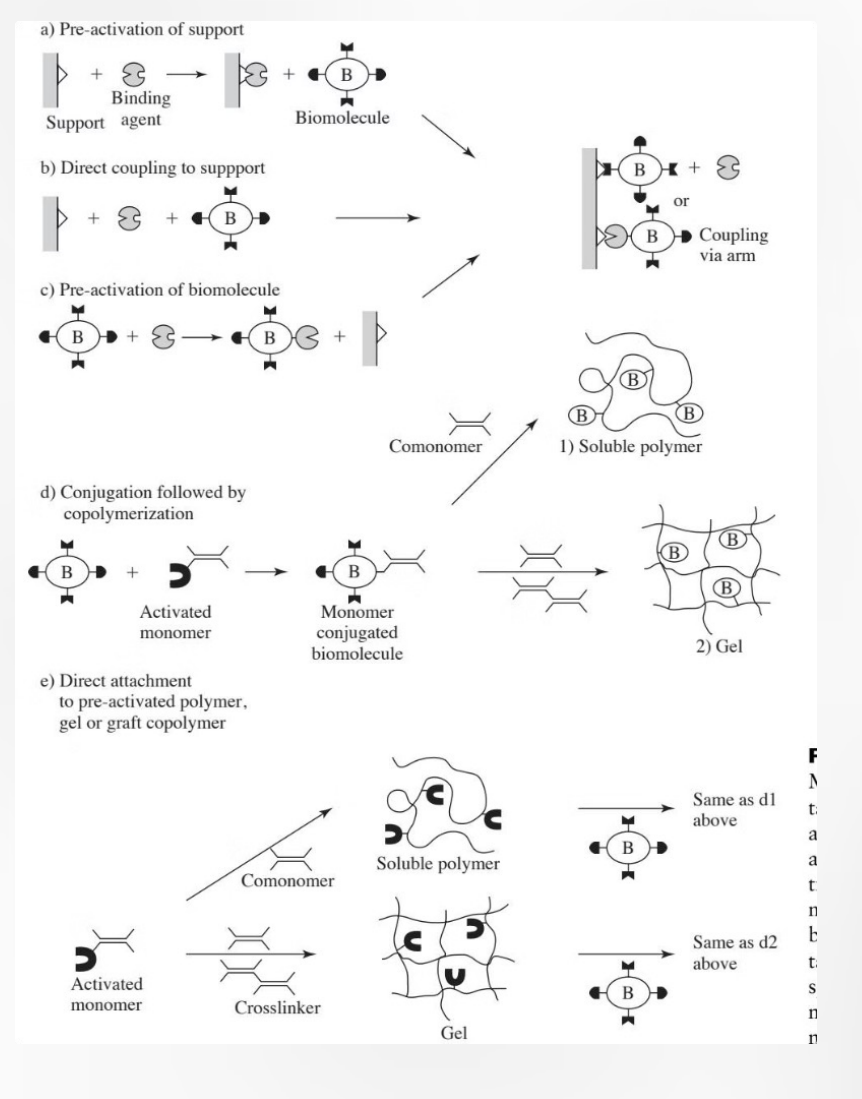
Covalent Biological Coatings
"Permanent" way to attach the biomolecules we just discussed.
1.) Reactive Surface (Surface requires hydroxyl, carboxyl, or amine groups for attachment) (Before you can attach a biomolecule, the surface usually needs to be "primed." A standard inert plastic won't bond easily. You need specific chemical "anchors") (These are often created using the Plasma Treatment or Radiation Grafting methods from your first slides)
2.) Spacer Arm (Inert molecule provides necessary physical space between surface and coating) (biomolecules (like proteins) need to move and fold to work) (If you bond a protein directly to a flat, hard surface, it can get "squashed" or its active site might be blocked) (A Spacer Arm is a small, flexible, inert molecule that acts like a tether. It holds the biomolecule away from the surface so it has the "elbow room" to rotate and interact with cells).
3.) Stability: Resulting covalently linked coatings provide long-term stability.
Case Study: Heparin Coating on Medical Devices
Blood-contacting devices like catheters (thin, flexible tubes that doctors insert into the body to either drain fluids, deliver fluids, or access internal areas for medical procedures) and stents (small mesh tubes that doctors place inside narrowed or blocked blood vessels [or other passages] to keep them open) face high risk of thrombosis (clot forms inside a vessel and obstructs circulation) (A clot [called a thrombus] is a mass of blood that has thickened and stuck together) formation. Traditional surfaces trigger blood clotting, leading to device failure and patient complications.
Heparin Solution: COVALENT attachment of heparin creates a biocompatible surface. The ANTICOAGULANT coating prevents clot formation, extending device lifetime from days to months and reducing patient risks.
This FDA-approved surface modification technique has become the gold standard for blood-contacting medical devices, with over 20 years of clinical success.
Diagram: The diagrams on the right illustrate two different ways to anchor Heparin (H) to a surface, mirroring the strategies we've discussed:
(a) Hydrophobic & Covalent Attachment: The Setup: A hydrophobic material (like many medical-grade polymers) is modified with a hydrophobic moiety (the "spacer arm" we talked about earlier). The Goal: This provides the necessary flexibility for the Heparin molecule to remain active and interact with blood proteins.
(b) Electrostatic (Ionic) Attachment: The Setup: The material is treated to have a positive charge (+). The Mechanism: Because Heparin is naturally highly negatively charged, it "STICKS" to the surface via strong electrostatic attraction. Note: While ionic bonds are shown here, the text emphasizes that covalent attachment is often preferred for "gold standard" devices because it ensures the Heparin doesn't slowly wash away (leach) into the blood over time.
![<p>Blood-contacting devices like catheters (thin, flexible tubes that doctors insert into the body to either drain fluids, deliver fluids, or access internal areas for medical procedures) and stents (small mesh tubes that doctors place inside narrowed or blocked blood vessels [or other passages] to keep them open) face high risk of thrombosis (clot forms inside a vessel and obstructs circulation) (A clot [called a <strong>thrombus</strong>] is a mass of blood that has thickened and stuck together) formation. Traditional surfaces trigger blood clotting, leading to device failure and patient complications.</p><p>Heparin Solution: COVALENT attachment of heparin creates a biocompatible surface. The ANTICOAGULANT coating prevents clot formation, extending device lifetime from days to months and reducing patient risks.</p><p>This FDA-approved surface modification technique has become the gold standard for blood-contacting medical devices, with over 20 years of clinical success.</p><p></p><p>Diagram: The diagrams on the right illustrate two different ways to anchor Heparin (H) to a surface, mirroring the strategies we've discussed:</p><p>(a) Hydrophobic & Covalent Attachment: <strong>The Setup:</strong> A hydrophobic material (like many medical-grade polymers) is modified with a <strong>hydrophobic moiety</strong> (the "spacer arm" we talked about earlier). <strong>The Goal:</strong> This provides the necessary flexibility for the Heparin molecule to remain active and interact with blood proteins.</p><p>(b) Electrostatic (Ionic) Attachment: <strong>The Setup:</strong> The material is treated to have a <strong>positive charge (+)</strong>. <strong>The Mechanism:</strong> Because Heparin is naturally highly <strong>negatively charged</strong>, it "STICKS" to the surface via strong electrostatic attraction. <strong>Note:</strong> While ionic bonds are shown here, the text emphasizes that <strong>covalent attachment</strong> is often preferred for "gold standard" devices because it ensures the Heparin doesn't slowly wash away (leach) into the blood over time.</p><p></p>](https://assets.knowt.com/user-attachments/08de629a-a10c-45d7-943f-67ffab37970a.png)
Immobilized Enzymes
Process: Attaching enzymes to SOLID substrates. Has applications in biosensors, controlled release devices, protein analysis.
Bioactivity: Dependent on the action of the enzyme. Techniques range from adsorption to covalent linkages with spacer arms.
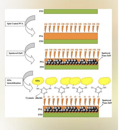
Case Study: Glucose Oxidase Biosensor: Immobilized glucose oxidase on electrospun nanofibers achieved 95% enzyme retention after 30 days. Used spacer-arm technique for covalent attachment, resulting in 3x higher sensitivity compared to direct binding. Clinical validation showed accurate glucose detection in range 2-25 mmol/L, making it suitable for continuous glucose monitoring devices.
The diagram on the right illustrates the sophisticated "layer-cake" construction of a biosensor:
FTO Substrate: The base layer is Fluorine-doped Tin Oxide (FTO), which is a conductive glass used to transmit the electrical signal. Spin-Coated PVA: A layer of Polyvinyl Alcohol (PVA) is added. Notice the -OH (hydroxyl) groups pointing up—this is exactly the kind of "reactive surface" mentioned in the earlier slides. Sputtered Nano-ZnO: Zinc Oxide nanoparticles are added to increase the surface area and improve the electrical connection. GOx Immobilization: Finally, the Glucose Oxidase enzyme (the yellow clouds) is attached. Cyanuric Chloride: This molecule acts as the "cross-linker" or bridge between the PVA/ZnO base and the enzyme. The Result: This setup achieved 95% enzyme retention over 30 days and 3x higher sensitivity than direct binding.
Bioactive Glasses Composition
Composition: Impact Bioactive glasses' composition affects integration. Layer Formation: Certain compositions form CaO/P2O5 and SiO2 layers. Precipitation: Promotion Promotes calcium-phosphate precipiation.
Bioactive glasses are unique because they don't just "sit" in the body; they undergo a controlled corrosion process that leads to Layer Formation. The Process: When these glasses touch body fluid, they release specific ions that form a SILICA-rich (SiO_2) layer, followed by a calcium-phosphate (CaO/P_2O_5) layer. Precipitation Promotion: This layer eventually CRYSTALLIZES into hydroxyapatite—the same mineral that makes up your bones and teeth. This allows the bone to bond directly to the glass!!!
The triangle on the left is a Ternary Plot used to show how changing the recipe of the glass changes its biological behavior. The three corners represent:
SiO_2 (Silica): The "glass former." Too much of this makes the glass inert (like a window pane).
CaO (Calcium Oxide): Essential for forming the bone-like layer.
Na_2O (Sodium Oxide): Helps the glass dissolve at the right speed.

Surface Strategy to Improve Wettability
Plasma Treatment: Uses ionized gas to create polar groups like hydroxyls (-OH).
UV/Ozone: Uses light to break bonds and oxidize the surface (adds oxygen-containing groups to the surface; examples of polar molecules or polar functional groups).
Chemical Etching: Uses acids (like the HCl/H_2SO_4 case study) to create PITS and increase surface energy (REMEMBER => increasing surface energy; high surface energy [solid] => strongly attaches liquid => liquid spreads out; low surface energy (solid) => weak attraction => liquid beads up).
Surface Strategy to Prevent Protein Adsorption
PEG Grafting: Attaching Polyethylene Glycol chains. PEG acts like a "fuzzy" barrier that prevents proteins from reaching the surface.
SAMs (Self-Assembled Monolayers): Using HYDROPHILIC (function head groups) terminals to create a water-rich "shield" that proteins can't penetrate.
Zwitterionic Coatings: Using molecules with both positive and negative CAHRGES to create a tight hydration layer.
Strategies to Promote Cell Adhesion
RGD Peptide Immobilization: Attaching specific amino acid sequences (Arg-Gly-Asp) that act as "VELCRO" for cell receptors.
Roughness Etching: Using lasers or acids to create the micro-scale texture cells prefer.
Bioactive Glass Coatings: Growing a hydroxyapatite layer that chemically mimics bone.
Overcoming Protein Corona Challenges
Addressing the protein corona is crucial for the effective in vivo performance of nanoparticles. Here are several strategic approaches:
Prevention: Apply antifouling (stopping things from sticking and growing on a surface) polymers like PEG to the nanoparticle surface to resist protein adsorption, minimizing corona formation before attaching targeting molecules (adding specific molecules onto the surface of the nanoparticle so it can recognize and bind to a particular biological target (like certain cells or tissues) (nanoparticle has A protective PEG layer anti-stick + specific targeting ligands sticking out) (With targeting molecules: the nanoparticles bind to specific cells [e.g., cancer cells]. This improves precision drug delivery). Ex. A nanoparticle designed for cancer therapy might: be coated with PEG + have an antibody attached => binds to receptors only found on tumor cells.
Detection: Utilize advanced analytical techniques such as XPS or mass spectrometry to identify specific proteins forming the corona, guiding the design of more effective surface coatings.
Mechanical Design: nanoparticles with targeting antibodies positioned on a "stalk" or FURTHER from the core, ensuring they remain accessible and functional even if a corona forms.
Chemical: Modify the targeting antibodies themselves with elements like PEG tails, which help them remain exposed and avoid being buried by the protein corona layer.
Dynamic: Shift from preventing to actively engineering the corona. Design nanoparticles to intentionally recruit beneficial proteins (e.g., opsonins) that can trigger desired biological responses or aid targeting.
Water as a Critical Solvent for Biomaterial Interactions
Readily dissolves hydrophilic substances (those with polar covalent bonds), while repelling hydrophobic ones.
Water: The First Responder: Before proteins even arrive, water molecules (due to their unique polarity and bent shape) swarm the surface. The Solvent Effect: Water creates a dynamic environment. If your surface is hydrophilic (water-loving), it forms a "hydration shell" that can actually help repel certain proteins.
Amino Acids
EACH amino acid features a central α-carbon, an amine group, a carboxyl group, and a unique variable R group (dictates if that specific building block is hydrophobic, hydrophilic, or charged). In nature, amino acids predominantly exist as the L (LOSER) stereoisomer, which is crucial for protein structure and function.
Amino acids link together through peptide bonds, forming long polypeptide chains that fold into functional proteins.
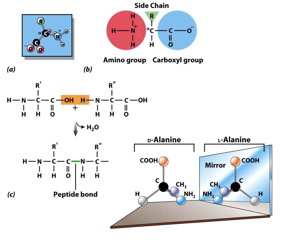
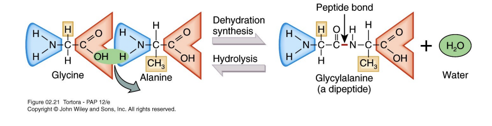
The Peptide Bond: Linking Amino Acids
Dipeptides, the foundational units of proteins, are formed when two amino acids unite through a strong covalent linkage called a peptide bond. This essential biochemical reaction occurs via dehydration synthesis, where a molecule of water is removed.
Covalent bonds involve the sharing of valence electrons between atoms (Because the atoms are physically sharing valence electrons, they are locked together in a high-energy state. This ensures that the proteins in your body—or the protein layer that adsorbs onto your engineered implant—remain structurally intact even when subjected to the flow of blood or changing pH levels.). The peptide bond is critical for building polypeptide chains. Polypeptide chains vary significantly in length, commonly containing between 10 to 2000 amino acids to form diverse functional proteins.
Reversibility: The reverse process, hydrolysis, adds water back into the system to break the peptide bond.
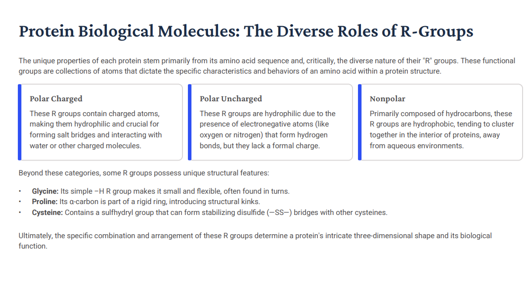
Protein Biological Molecules: The Diverse Roles of R-Groups
The unique properties of each protein stem primarily from its amino acid sequence and, critically, the diverse nature of their "R" groups. These functional groups are collections of atoms that dictate the specific characteristics and behaviors of an amino acid within a protein structure.
R group can be:
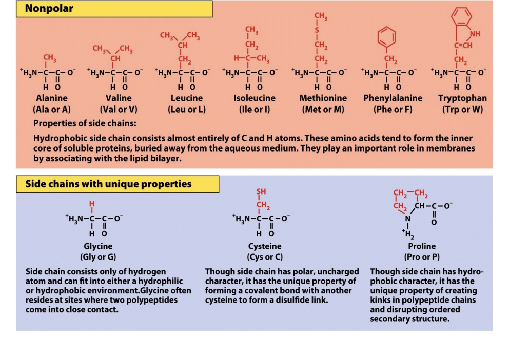
Nonpolar (Hydrophobic): Mostly hydrocarbons. These "hide" from water and cluster in the interior of proteins, away from aqueous environments. If your surface is hydrophobic, these groups will flip outward to stick to it.
Polar UNCHARGED (Hydrophilic): These have electronegative atoms like Oxygen or Nitrogen. They love to form hydrogen bonds with water. However! They LACK a formal charge!
Polar Charged: contain charged atoms, making them HYDROPHILIC and crucial for forming SALT BRIDGES and interacting with water or other charged molecules. These are highly reactive and form SALT BRIDGES. They are crucial for interacting with surfaces you’ve modified to have a specific surface charge.
Beyond these categories, some R groups possess unique structural features:
Glycine: Its simple –H R group makes it small and flexible, often found in turns! Because it’s so small, it is the most flexible amino acid. Glycine the Gymnast. It allows protein chains to make sharp turns and fit into tiny nooks on a biomaterial's surface.
Proline: Its α-carbon is part of a rigid ring, introducing structural kinks. Proline = Pretzel = a ring = incredibly stiff. If a protein needs to hold a very specific, awkward shape to stay adsorbed to your substrate, Proline is usually the reason.
Cysteine: Contains a sulfhydryl group that can form stabilizing disulfide (—SS—) bridges with other cysteines. Cysteine Connects.
Ultimately, the specific combination and arrangement of these R groups determine a protein's intricate three-dimensional shape and its biological function.
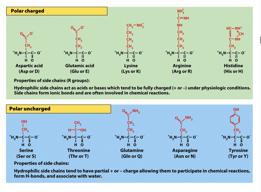
Chemical Structure of Amino Acids
More Chemical Structure of Amino Acids
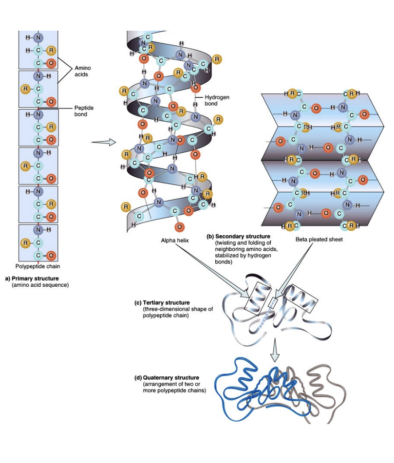
Protein Structural Organization
Proteins exhibit a remarkable hierarchy of structural organization, from simple linear chains to complex three-dimensional forms, each level critical for their biological function.
Primary Structure: The unique linear sequence of amino acids linked by peptide bonds.
Secondary Structure: LOCAL FOLDING into α-helices and β-sheets, stabilized by hydrogen bonds.
Tertiary Structure: The overall 3D shape of a single polypeptide chain, formed by interactions BETWEEN R-groups.
Quaternary Structure: The arrangement of multiple polypeptide subunits (if present) to form a functional protein complex.
The intricate final shape dictates a protein's ability to recognize and bind to other molecules. Any disruption, such as denaturation from a hostile environment, leads to a loss of this characteristic shape and, consequently, its biological function.
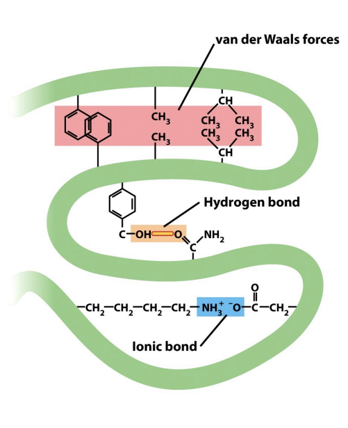
Interactions Stabilizing Types of noncovalent bonds maintaining the conformation of proteins
While peptide bonds form the protein backbone, its precise three-dimensional structure is largely dictated by a complex interplay of weaker, non-covalent interactions between amino acid R-groups (think tertiary structure!). These forces are critical for protein folding and function.
Hydrophobic & Van der Waals: Nonpolar groups associate to minimize contact with water. Van der Waals forces, weak attractions from transient dipoles, stabilize these associations within a protein's core.
Hydrogen Bonds: Formed when a partially positive hydrogen atom attracts electrons from another electronegative atom. These bonds are essential for water's properties and key to stabilizing α-helices and βsheets .
Ionic Bonds: Electrostatic attractions between oppositely charged groups. Though diminished in water, they can be significant within specific regions of large proteins, contributing to their tertiary structure.
Diagram is pretty nice!
Some more clarification: Ionic bonds (sometimes called “salt bridges”) can contribute to tertiary structure, but they are less stable and more sensitive to pH and environment. Covalent bonds (like DISULFIDE bridges, when present) are much stronger and more permanent. These ionic bonds are also weaker than the peptide backbone of protein, which is made of covalent bonds.
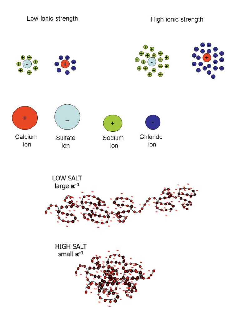
Effect of Ionic Strength of Solution
Low ionic strength: the electric double layer (Debye length, κ⁻¹) extends FAR from charged surfaces, so electrostatic attractions and repulsions BETWEEN proteins and surfaces act over LONGER distances!
Chat: The relationship between your negatively charged surface and amino acids is controlled by a phenomenon called Debye Screening. If you have a negatively charged surface, it will most strongly attract Polar Charged amino acids that carry a positive charge, such as Lysine or Arginine. However, the "strength" of this attraction isn't just about the charge; it depends heavily on the Ionic Strength of the surrounding fluid (like blood or saline). So for Low Ionic Strength: The Electric Double Layer extends far from the surface. There aren't many dissolved ions in the water to get in the way, so your negative surface can "reach out" and PULL in positive proteins from a long distance!
High ionic strength (The “Screening Effect”): dissolved ions screen surface and protein charges, compressing the double layer. This weakens electrostatic interactions but can unmask hydrophobic forces, changing which proteins adsorb and how tightly; in high-salt environments like physiological saline, the water is crowded with Na+ and Cl- ions. Those dissolved ions SWARM the surface and protein, “screening” or masking their charges! This screening effect is why electrostatics alone rarely dictate how a medical implant works in vivo: Because the salt in your blood compresses the double layer, the strong electrostatic "magnets" are weakened. This UNMASKS shorter-range forces, meaning Hydrophobic and Van der Waals forces often end up dominating how proteins actually stick to your device!!
Low Salt (solution)/ionic strength: large Debye length.
High Salt/ionic strength: small Debye length.
Clinical relevance: physiological saline (~150 mM NaCl) (a solution of sodium chloride in water that is specifically designed to match the concentration of salts found in the human body!) partially screens charges — meaning hydrophobic and van der Waals forces often dominate protein adsorption in vivo, not electrostatics alone!
Clarification: Debye length = the “radius of influence” for a charged surface. It describes how far into the surrounding liquid the surface's electric field can actually "reach" before it gets smothered by other ions.
More Clarification: Electrical Double Layer: This forms when a charged surface is in contact with a liquid (like water). What happens: a surface (like a protein, membrane, or electrode) has charged groups. Oppositely charged ions in the surrounding solution gather near that surface. This creates two layers of charge: inner layer (ions are tightly bound to the surface & opposite charge to the surface) and outer layer (loosely associated ions and more spread out into the solution).
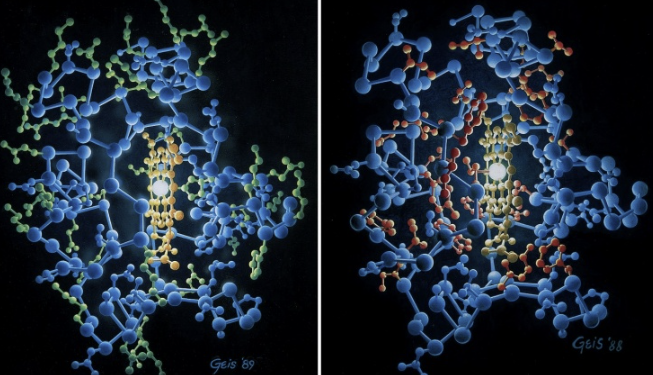
Hydrophobic and Hydrophilic Amino Acid Residues in the Protein Cytochrome C
Illustrates the spatial distribution of amino acids within cytochrome c, a small hemeprotein found in the inner membrane of the mitochondria. The two panels use a color-coding system to highlight the “ hydrophobic effect,” which is the primary driving force behind protein folding. In an aqueous environment, proteins fold such that they reach the lowest energy state. This usually results in a specific arrangement of their amino acid residues.
The Left Panel: Hydrophilic Residues (Green): Location: Green spheres are predominantly located on the surface of the protein. These are water-loving (hydrophilic) side chains. Because they are polar or charged, they can form hydrogen bonds with the surrounding water molecules, stabilizing the protein’s exterior.
Right Panel: Hydrophobic Residues (Red). Red spheres are concentrated in the interior (the core) of the protein. Function: These are water-fearing (hydrophobic) side chains. To minimize contact with water, they pack together tightly in the center. This creates a “hydrophobic core,” which acts like a drop of oil in water and provides the structural stability needed to hold the protein’s shape.
The Heme Group: In the center of both images, you can see a bright, yellowish planar structure. This is the heme prosthetic group. Cytochrome c uses this heme group to carry electrons during cellular respiration.
Why This Matters: This specific arrangement is critical for the function of cytochrome c. By sequestering the hydrophobic residues inside, the protein creates a stable environment for the heme group to facilitate electron transfer. If the protein were to unfold (denature), these hydrophobic residues would be exposed to water, causing the protein to lose its functional shape and potentially clump together (aggregate).
Impact of Protein Structure: Sickle Cell Anemia
Sickle cell anemia is a stark example of how even a SINGLE amino acid change can disrupt protein structure at every level, leading to severe disease. A point mutation in the beta-globin chain of hemoglobin replaces a hydrophilic glutamate with a HYDROPHOBIC valine. This primary structure alteration creates a sticky patch on the protein's surface. When deoxygenated, these altered hemoglobin molecules (secondary and tertiary changes) aggregate into long, rigid fibers. This abnormal quaternary structure polymerizes, deforming red blood cells into a sickle shape, causing blockages and oxygen deprivation!!
Clarifications:
Secondary and Tertiary Structure: Sticky Patch: In normal hemoglobin, glutamate sites on the protein’s surface, interacting comfortably with the watery environment of the red blood cell. However, because valine is hydrophobic, it seeks to AVOID water. This creates an abnormal sticky, hydrophobic patch on the surface of the hemoglobin molecule (Interesting??).
Quaternary Structure: Polymerization: When oxygen levels are low (deoxygenated state), these sticky patches on different hemoglobin molecules find each other and "lock" together to hide from the water. Instead of remaining as INDIVIDUAL, soluble tetramers (Normal Hemoglobin), the mutant molecules AGGREGATE into long, rigid polymers or fibers (Clumped Hemoglobin).
Cellular Impact: The Sickle Shape: These rigid fibers act like structural rods inside the red blood cell. They push against the cell membrane, distorting the normally flexible, disc-shaped cell into a RIGID crescent or "sickle" shape.
PHYSIOLOGICAL CONSEQUENCES: Unlike normal red blood cells, which are flexible enough to squeeze through the tiniest capillaries, sickle cells are stiff and brittle. Blockages: They get STUCK in small blood vessels (vaso-occlusion), blocking blood flow. Oxygen Deprivation: This leads to intense pain, organ damage, and anemia, as the sickle cells break down much faster than healthy cells. Clarification: Rapid breakdown of sickle cells = hemolysis. While a healthy red blood cell typically circulates for about 120 days, a sickle cell only survives 10 to 20 days (one reason is the hemoglobulin with sickle cells is chemically unstable [Hemoglobulin S]; it tends to break down and release free iron [heme] and reactive oxygen species inside the cell; this internal “chemical fire” further damages the cell’s internal machinery and membrane from the inside out). Because the bone marrow cannot keep up with the pace at which the cells are being destroyed, the body enters a state of chronic anemia. Symptoms include: Fatigue and Shortness of Breath: Due to fewer functional cells to carry oxygen.
![<p>Sickle cell anemia is a stark example of how even a SINGLE amino acid change can disrupt protein structure at every level, leading to severe disease. A <strong>point mutation </strong>in the beta-globin chain of hemoglobin replaces a <strong>hydrophilic glutamate with a HYDROPHOBIC valine</strong>. This primary structure alteration creates a <strong>sticky patch on the protein's surface</strong>. <strong>When deoxygenated, these altered hemoglobin molecules (secondary and tertiary changes) aggregate into long, rigid fibers. This abnormal quaternary structure polymerizes, deforming red blood cells into a sickle shape, causing blockages and oxygen deprivation</strong>!!</p><p>Clarifications: </p><p>Secondary and Tertiary Structure: Sticky Patch: In normal hemoglobin, glutamate sites on the protein’s surface, interacting comfortably with the watery environment of the red blood cell. However, because valine is hydrophobic, it seeks to AVOID water. This creates an abnormal <strong>sticky</strong>, hydrophobic patch on the surface of the hemoglobin molecule (Interesting??).</p><p>Quaternary Structure: Polymerization: When oxygen levels are low (deoxygenated state), <strong>these sticky patches on different hemoglobin molecules find each other and "lock" together to hide from the water.</strong> Instead of remaining as INDIVIDUAL, soluble tetramers (Normal Hemoglobin), the mutant molecules AGGREGATE into <strong>long, rigid polymers or fibers</strong> (Clumped Hemoglobin).</p><p>Cellular Impact: The Sickle Shape: These rigid fibers act like structural rods inside the red blood cell. They push against the cell membrane, distorting the normally flexible, disc-shaped cell into a RIGID <strong>crescent or "sickle" shape</strong>.</p><p>PHYSIOLOGICAL CONSEQUENCES: Unlike normal red blood cells, which are flexible enough to squeeze through the tiniest capillaries, sickle cells are stiff and brittle. <strong>Blockages:</strong> They get STUCK in small blood vessels (vaso-occlusion), blocking blood flow. <strong>Oxygen Deprivation:</strong> This leads to intense pain, organ damage, and anemia, as the sickle cells break down much faster than healthy cells. Clarification: Rapid breakdown of sickle cells = hemolysis. While a healthy red blood cell typically circulates for about 120 days, a sickle cell only survives 10 to 20 days (one reason is the hemoglobulin with sickle cells is chemically unstable [Hemoglobulin S]; it tends to break down and release free iron [heme] and reactive oxygen species inside the cell; this internal “chemical fire” further damages the cell’s internal machinery and membrane from the inside out). Because the bone marrow cannot keep up with the pace at which the cells are being destroyed, the body enters a state of <strong>chronic anemia</strong>. Symptoms include: <strong>Fatigue and Shortness of Breath:</strong> Due to fewer functional cells to carry oxygen.</p><p></p>](https://assets.knowt.com/user-attachments/e4dc46b3-a1c4-4f7c-b1a6-a2f377565489.png)
Overview: Biomaterial-Biological Fluid Interactions
When Biomaterials contact Biological Fluids.
Molecular Transport: BIOMOLECULES from the SURROUNDING fluid rapidly move towards and accumulate on the material surface.
Protein Adsorption: Proteins selectively BIND to the surface, forming a dynamic initial layer, driven by various physicochemical forces.
Conformational Change: Adsorbed proteins may undergo structural alterations, influencing their biological activity and recognition.
Thermodynamics of Adsorption: Gibbs Free Energy
Protein adsorption on biomaterial surfaces is fundamentally a thermodynamic process, driven by changes in the system's Gibbs free energy. This energy dictates the spontaneity of the adsorption event.
deltaG = deltaH - TdetaS
Memory: “The Shit” = negative term.
deltaG = Gibbs Free Energy = The overall change in energy of the system, determining if the process is spontaneous (favored) or requires energy input.
T = Absolute Temperature = The temperature of the system in Kelvin. It amplifies the effect of entropy on the overall free energy.
deltaH = enthalpy change = Represents the heat absorbed or released during adsorption.
deltaS = entropy change = Measures the change in disorder or randomness. An increase in entropy (ΔS > 0) is often a major driving force for protein.
For protein adsorption to be thermodynamically favored and occur spontaneously, the change in Gibbs free energy (ΔG) must be less than zero (deltaG < 0).
Driving Forces: Enthalpy vs. Entropy
The spontaneity of protein adsorption is a delicate balance between the ENERGETIC changes (enthalpy) and the CHANGES in molecular ORDER (entropy), both contributing to the overall Gibbs free energy change.
ΔH: Enthalpy (INTERACTION Energies!!!!!!): Represents the heat absorbed or released due to direct interactions between the protein AND the surface. Includes ATTRACTIVE or REPULSIVE electrostatic forces between CHARGED groups. Accounts for WEAK van der Waals forces (dispersion, dipole-dipole) that govern molecular proximity. Can be favorable (exothermic, deltaH < 0) IF STRONG new bonds form between the protein and the surface.
deltaS: Entropy (Molecular Disorder): Measures the change in the overall disorder or randomness of the system. A significant driver is the release of STRUCTURED water molecules from BOTH the protein and the surface upon adsorption. Changes in protein flexibility (often a decrease in its conformational entropy) are also considered (makes sense). An increase in system entropy (ΔS > 0) is highly favorable for adsorption. “This Shit” = negative term.
The absolute temperature (T) acts as a multiplier for the entropic contribution, determining the relative importance of enthalpy and entropy in dictating the spontaneity of adsorption.
Clarification: Enthalpy (deltaH): Enthalpy accounts for the “tightness” of the bond between the protein and the surface. It is favorable (deltaH < 0) when the energy RELEASED by FORMING NEW BONDS (think of the satisfaction, energy released, into putting two legos together, AKA forming a bond) is GREATER than the energy required to BREAK old ones (like stripping away the hydration layer) (stripping away hydration layer: energetic and physical cost of removing the water molecules that are tightly bound to a surface or a protein before they can touch each other) (think it takes energy to break a block [lego block or karate block] into two).
Still Under Enthalpy Section: Electrostatic Forces: Interaction between charged amino acid side chains (like lysine or glutamate) and a charged biomaterial surface. Van der Waals Forces: Weak, short-range attractions that become SIGNIFICANT once the protein is in very close proximity to the surface. Take with salt: Additive Power: A protein consists of thousands of atoms. When a protein "flattens" or spreads out on a surface (conformational change), it maximizes the number of atoms in close contact with the material. Thousands of tiny Van der Waals interactions summed together create a very strong, stable bond.
Entropy (deltaS): The Physics of Disorder: The Water Release: This is the most critical point. Water molecules "structure" themselves around hydrophobic surfaces and proteins. When the protein ADSORBS, these water molecules are liberated, greatly INCREASING the randomness of the system (once the liberated water molecules are back in the bulk liquid, they are free to tumble, rotate, and swap positions. Their freedom o movement increases). Protein Flexibility: Interestingly, entropy can sometimes work against adsorption. When a protein STICKS to a surface and spreads out, it may lose its ability to "wiggle" (conformational entropy). This decrease in flexibility (Delta S < 0) must be overcome by the much larger increase in entropy from the released water!!!
Why Adsorption Occurs: The Drive to Lower Energy
Protein adsorption is not a random event but a thermodynamically favorable process where the entire system—protein, surface, and solvent—moves towards a more stable, lower energy state!
Water Molecules Displaced: Highly ORDERED water molecules surrounding the protein and surface are released, significantly INCREASING the entropy of the system (okay).
Protein-Surface Interactions: Favorable non-covalent interactions (e.g., van der Waals, electrostatic, hydrophobic, hydrogen bonds) form between the protein and the biomaterial.
Formation of New Bonds: These interactions lead to the creation of new, more STABLE protein-surface BONDS, which can contribute to a negative enthalpy change.
The combination of these factors results in an overall decrease in the Gibbs free energy (ΔG < 0), making protein adsorption a spontaneous process.
Clarification: Once the water is out of the way, the protein and surface can finally engage in non-covalent interactions! Hydrophobic Interactions: "Water-fearing" parts of the protein find "water-fearing" parts of the surface. Electrostatic/Hydrogen Bonds: Positive and negative charges align, or POLAR groups share hydrogen atoms. Van der Waals: The short-range flickering attractions that lock everything into place.
AS these interactions occur, new bonds are created. Energy Release: Forming a stable bond is an exothermic process, meaning it releases heat/energy into the surroundings (deltaH < 0). Stability: This decrease in enthalpy further “lowers the floor” of the system’s energy.
Protein-Surface Interactions
The binding of proteins to a biomaterial surface is governed by a complex interplay of non-covalent interactions. Understanding these forces is crucial for predicting and controlling protein adsorption.
Van der Waals Forces: weak, short-range attractive forces arising from temporary dipoles in molecules.
Electrostatic Interactions: Attractions or repulsions between charged groups on the protein and the surface!!
Hydrophobic Interactions: The tendency of non-polar molecules to aggregate in aqueous solution, DRIVEN by entropy!!
Hydrogen bonding: Relatively STRONG dipole-dipole interactions (stronger than van der Waals but less strong than covalent bonds) (strong enough to hold a protein to a surface firmly but weak enough to allow the protein to wiggle, unfold, or change shape [conformational change] as it settles onto the material) involving hydrogen atoms bonded to EN atoms.
The specific chemistry and topography of the biomaterial surface critically influence which of these non-covalent interactions will dominate and dictate the adsorption profile.
Clarification: Although van der Waals are weak individually, they become a major force when a protein “flattens” itself against a surface, allowing thousands of atoms to be in close proximity.
Electrostatic Interactions Ex. A positively charged Lysine on the protein and a negatively charged oxide layer on a metal.
Electrostatic Interactions are highly sensitive to the ENVIRONMENT! Changing the pH can flip the charge of a protein, potentially turning an attraction into a repulsion!
Hydrophobic Interactions: (INTERESTING!): “The Entropy Driver”; this is often the most significant factor for medical plastics (polymers); Mechanism: Non-polar (hydrophobic) regions of the protein want to hide from water. They do this by "nestling" against the hydrophobic surface of the biomaterial, which releases the structured water around them and lowers the system's energy. More Clarification: Because water is a polar molecule that loves to hydrogen bond, it is very uncomfortable next to a hydrophobic (non-polar) surface. It can't bond with that surface. Because water is a polar molecule that loves to hydrogen bond, it is very uncomfortable next to a hydrophobic (non-polar) surface. It can't bond with that surface. High Order: These water molecules are "trapped" in a specific orientation. The "Nestling" (During Adsorption): When the hydrophobic region of the protein "nestles" against the hydrophobic surface of the biomaterial, they physically touch and exclude the water from that interface. The "Hiding" Effect: By sticking together, the protein and the surface are effectively "shielding" each other from the water they both "dislike." The moment they touch, those "cages" of water are smashed!!! The Release: The water molecules that were once rigidly ordered are now "kicked out" into the bulk liquid. Freedom: In the bulk liquid, they can tumble, rotate, and move randomly. This massive increase in water's freedom (disorder) is a huge increase in entropy. Interesting!!!
More on Why Chemistry and Topography Matter: Chemistry: A Teflon surface will be dominated by hydrophobic force, while a Glass surface will be dominated by hydrogen bonding and electrostatics! Topography: A rougher surface increases the actual contact area, allowing for significantly more Van der Waals and Hydrophobic contact points!!!
Even more Clarification on “A Teflon surface will be dominated by hydrophobic force, while a Glass surface will be dominated by hydrogen bonding and electrostatics!” => The comparison highlights the two extreme in biomaterial surface science: the non-polar/low-energy surface (Teflon) VERSUS the polar/high-energy surface (Glass). Reminder: low-energy surface = material surface that has LOW surface free energy = hydrophobic. Teflon consists of a carbon-backbone entirely “shielded” by fluorine atoms (CF2-CF2). Because fluorine is so EN, it holds onto its electrons very tightly, making the molecule extremely stable and non-polar. Why Hydrophobic Forces Dominate: The “Water Hatred”: Water cannot form hydrogen bonds with Teflon. As a result, water molecules at the Teflon interface are highly “unhappy” and ordered in those rigid, low entropy cages. The Entropic Push: When a protein (which has its own hydrophobic patches) approaches, the system “realizes” it can eliminate two hydrophobic interfaces by sticking them together.
Glass: Glass is a forest of Silanol groups (Si-OH). This makes the surface fundamentally different from the “inert” shield of Teflon. Why Hydrogen Bonding Dominates: Chemical Hooks: The -OH groups on the GLASS act as active partners. They don’t just wait for the water to be pushed away; they actively “reach out” to form hydrogen bonds with the polar side chains of amino acids (like Serine or Threonine) or the protein’s peptide backbone. High Surface Energy: Glass has a high affinity for polar molecules. The ENTHALPY change (deltaH) here is very favorable because strong new bonds are being formed. Why Electrostatics Dominate: Surface Charge: In water at physiological pH (~7.4), glass loses protons to become negatively charged (SiO-). The Coulombic Pull: This creates a long-range “attraction zone.” While Teflon only interacts with a protein when it’s practically touching, Glass can “pull” a positively charged protein toward it from a much greater distance through the fluid.
Surface Chemistry Matters
The inherent properties of a biomaterial's surface are paramount in dictating the extent, rate, and conformation of adsorbed proteins. These properties include: surface charge, surface polarity, and surface topography.
Surface Charge: Electrostatic interactions are a primary force, with proteins seeking regions of complementary charge. Positive regions attract negatively charged protein domains. Negative regions attract positively charged protein domains.
Surface POLARITY: The balance between hydrophilic and hydrophobic areas influences water displacement and protein affinity. Hydrophobic regions often promote adsorption by displacing structured water. POLAR regions facilitate hydrogen bonding and dipole interactions.
Surface Topography: The physical landscape of the surface, from macro- to nanoscale features, impacts binding. Roughness can increase surface area and create sheltered binding pockets. Nanoscale features can guide protein orientation and conformational rearrangements.
By engineering these surface properties, we can strategically control protein adsorption and, consequently, the biological response to biomaterials.
Clarification: Polarity refers to the degree of hydrophilicity (water-loving) or hydrophobicity (water-fearing) of the surface. The Hydrophobic Effect: This is often the STRONGEST driving force for protein adsorption. Hydrophobic surfaces displace “structured water” (ordered layers of H20 molecules), which increases entropy and makes surface binding energetically favorable. Hydrogen Bonding: Polar surfaces interact with proteins via dipole-dipole moments and hydrogen bonds, often leading to more reversible or less denaturing adsorption compared to hydrophobic surfaces (Take with a grain of salt but interesting!!).
Surface Topography: Rougher surfaces provide more total SA for proteins to latch onto and can create “pockets" that shield proteins from shear forces (like blood flow)!
Kinetics vs. Thermodynamics in Protein Adsorption
Thermodynamics: Thermodynamics focuses on the stability of the final state of the adsorbed protein. It predicts whether adsorption is spontaneous and the equilibrium concentration of proteins on the surface. Dictates the equilibrium AMOUNT of protein adsorbed. Determines the driving force for adsorption (deltaG).
Kinetics: Kinetics describes the speed of adsorption and the mechanisms involved. It governs how quickly proteins reach the surface and undergo structural changes. Governs the RATE of protein diffusion to the surface. Influences the SPEED of initial binding and structural rearrangement.
Both kinetic and thermodynamic factors interact to determine the final protein surface coverage and its biological activity.
Protein Adsorption: A Reversible Reaction
To understand the fundamental principles governing protein adsorption, we can conceptualize it as a REVERSIBLE chemical reaction occurring at the biomaterial interface. Core model = to the left. It implies two competing processes: Adsorption: Proteins moving from the bulk solution to the surface. Desorption: Proteins detaching from the surface and returning to the solution.
The diagram at the BOTTOM of the slide shows the Surface Occupancy Effect. Low Surface Concentration (Left): When there are plenty of available sites, proteins have the “space” to unfold and maximize their footprint. This often leads to STRONGER, less reversible binding because the protein forms more contact points with the surface. High Surface Concentration (Right): As more proteins arrive, space becomes a premium. Proteins are forced to remain in a more upright, “compact” orientation. While this allows for more proteins to fit on the surface, they may be less stable and more likely to be desorbed or be replaced.
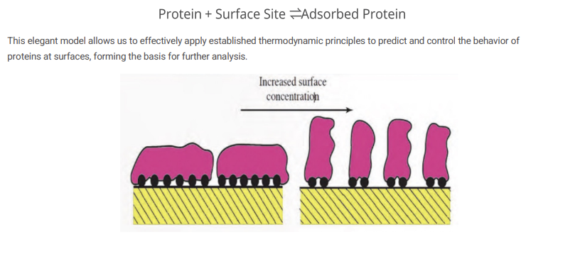
Protein Structural Changes
Protein remodeling POST-ADSORPTION is a critical event that dictates long-term biomaterial interactions.
Structural Rearrangement: Subtle shifts in the protein's conformation for better surface fit!
Unfolding: Partial or complete loss of native 3D structure, exposing new binding sites.
Conformational Change: Significant alterations that can impact protein activity and recognition by biological systems.
These changes typically INCREASE CONTACT WITH THE SURFACE AREA, affecting protein stability and subsequent biological responses.
Clarification: Structural Rearrangement: These are minor wiggles where the protein shifts its side chains to better align with surface charges or polar groups. Unfolding: The protein begins to lose its tertiary structure. This is a significant event because it can expose the hydrophobic core of the protein, which is normally tucked away from the water. Conformational Change: These are major alterations: If the shape changes enough, the protein’s active sites might be destroyed, or cryptic sites might be revealed.
Visual to Right: The bar graph on the right illustrates a counterintuitive point: More protein doesn't always mean better biological response. AH! Makes sense! The "Cell Adhesion Domains" (the black dots in the red protein spheres) represent specific sequences—like the RGD sequence in FIRBONECTIN—that cells use to "anchor" themselves to a surface. Surface 1 (High Activity): The protein adsorbs but maintains its orientation so the adhesion domains are facing "up" and are ACCSSIBLE to cells. Surface 2 (Medium Activity): Partial unfolding or unfavorable orientation hides some of these domains, making it harder for cells to stick. Surface 3 (Low Activity): Significant conformational change or "denaturation" occurs. The protein spreads out so much that the adhesion domains are either buried against the surface or physically distorted. Even though the protein is there, the cells "see" it as a foreign blob rather than a familiar anchor.
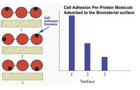
Conformational Flexibility and Protein Unfolding
The inherent flexibility of a protein significantly influences its ability to adsorb onto a biomaterial surface, often leading to more extensive and stable interactions.
Increased Binding Site Access: Proteins with GREATER conformational flexibility can undergo SIGNIFICANT unfolding, exposing INTERNA: hydrophobic regions or previously buried polar groups that act as NEW binding sites for the surface. Interesting!!
Maximized Surface Interactions: This exposure allows the protein to "spread out" and adapt its shape to better conform to the surface topography, thereby MAXIMIZING the number and type of non-covalent interactions (e.g., van der Waals forces, hydrophobic interactions, electrostatic bonds).
Stronger Adsorption Tendency: The cumulative effect of more accessible binding sites and OPTIMIZED surface contact leads to a more FAVORABLE change in Gibbs free energy, resulting in flexible proteins typically adsorbing more strongly and irreversibly.
Understanding this dynamic behavior is crucial for designing biomaterials that either resist or promote specific protein adsorption profiles.
Clarification: Because the flexible protein forms so many individual bonds, the cumulative binding energy is huge. This makes the adsorption IRREVERSIBLE—even if the individual bonds are weak, the statistical probability of all those bonds breaking at the exact same time is nearly zero.
Linking Back to Other Slide: Thermodynamic Driving Force: As mentioned in the previous slide on thermodynamics, the unfolding of a protein on a surface is an entropy-driven process. 1.) The protein starts in a highly-ordered 3D shape (low entropy). 2.) Upon contact, it unfolds into a disordered, spread-out state (high entropy). 3.) Simultaneously, water molecules are released from the surface (further increasing entropy). This massive increase in entropy leads to a very negative deltaGads, making the adsorption of flexible proteins highly spontaneous.
Competitive Adsorption
Biological environments, such as blood or tissue fluids, are complex mixtures containing numerous different proteins, all vying for interaction with a biomaterial surface.
Albumin: Highly abundant, often the first to arrive but weakly bound. It is the MOST ABUNDANT protein in the blood. Because of its high concentration and relatively small size, it has the HIGHEST collision frequency with the surface. It gets there first but doesn’t stick very strongly.
Fibrinogen: Critical for coagulation, known to induce (to cause something to happen or bring it about) cell adhesion. It is LARGER and less abundant than albumin but has a much HIGHER affinity for most surfaces. Its presence is a double-edged sword: it helps cells stick, but it also triggers the coagulation (clotting) cascade.
Immunoglobulins (Antibodies): Key immune proteins, signaling foreign body responses. If these proteins adsorb in high quantities, they can signal macrophages and other immune cells to attack the material, leading to chronic inflammation or the formation of a fibrous capsule!
VROMAN EFFECT: The "dynamic interplay" mentioned in the slide is best described by the Vroman Effect. It follows a predictable timeline: Phase 1 (Kinetics): Small, fast proteins like Albumin saturate the surface almost instantly because they are everywhere. Phase 2 (Competition): Larger proteins like Fibrinogen arrive. Even though there are fewer of them, they have a "stronger grip" (higher thermodynamic affinity). They begin to kick the Albumin off the surface. Phase 3 (Equilibrium): Eventually, high-affinity proteins like High Molecular Weight Kininogen (HMWK) may displace the Fibrinogen.
This dynamic interplay results in a constant competition for available surface sites, where the most competitive proteins can displace less strongly bound ones over time, influencing the long-term biological response.
Why This Matters for Design: To reduce clotting: Engineers might try to "pre-coat" a surface with Albumin. Since Albumin is generally non-thrombogenic (doesn't cause clots), keeping it there AND preventing Fibrinogen from displacing it is a common strategy for blood-contacting devices. To promote bone growth: Engineers might use surface chemistry that specifically favors the stable adsorption of Vitronectin or Fibronectin, which tell bone cells to start growing!!
Vroman Effect
A critical phenomenon in biomaterial-biological fluid interactions is the Vroman Effect, describing the dynamic replacement of adsorbed proteins over time. This displacement occurs because proteins with a higher affinity for the surface, often larger ones, can form MORE STABLE bonds, eventually outcompeting and replacing weaker-bound proteins. This effect profoundly influences long-term biomaterial biocompatibility.
Chat: The Displacement: The larger proteins essentially "push" the smaller ones off. This is energetically favorable because the stronger bonds of the larger protein release more energy than is required to break the weaker bonds of the smaller one.
Impact on Biocompatibility: The Vroman Effect is the reason why an implant's "biological identity" changes in the minutes and hours after surgery: Short-term: The surface is coated in Albumin (generally "stealthy" and non-reactive). Mid-term: Fibrinogen takes over (promoting cell adhesion but ALSO potentially blood clotting). Long-term: The final layer of proteins determines if the body sees the material as a "friend" (integrating it into tissue) or a "foe" (triggering the Foreign Body Response).
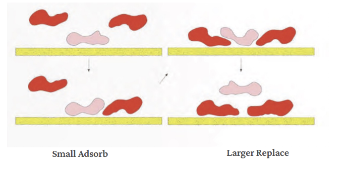
Kinetics: The Speed of Adsorption
Thermodynamics tells us whether adsorption is favorable; kinetics tells us how fast it proceeds.
Rate Controlling Factors: Adsorbate (the substance that gets attached to a surface during adsorption) concentration — higher bulk concentration drives faster adsorption (in blood, this is why Albumin wins the initial race!), Surface area — greater adsorbent (SURFACE that things stick to) area provides more binding sites (on a rough surface, the effective surface area is MUCH HIGHER than the geometric area), Temperature — increases molecular mobility and diffusion (increases the diffusion coefficient of the proteins, allowing them to move through the liquid faster), Activation energy — energetic barriers can limit the rate (even if a protein hits the surface, it might need to overcome an energetic barrier (like pushing though a hydration layer) to form a stable bond.
Adsorption rate rises sharply before tapering to an equilibrium plateau — the time to reach it depends on kinetic barriers.
Clarification: Analyzing the Adsorption Graphs: Graph Left: Initial Linear Phase: The straight line represents the diffusion-limited regime. Early on, every protein that reaches the surface sticks instantly because there are plenty of open sites. The rate depends entirely on how fast the proteins can diffuse from the BULK to the interface. Graph Right: This is a classic representation of competitive adsorption in complex fluids: The Sharp Rise: Fast-moving proteins (like Albumin) rapidly coat the surface. The Peak/Overshoot: The total mass on the surface reaches a maximum. The Dip: This represents the Vroman Effect in action. Larger, high-affinity proteins like Fibrinogen arrive and begin displacing the smaller proteins. Because the displacement ISN’T a 1-to1 mass exchange, you often see a temporary decrease in total surface concentration. 4.) The Equilibrium Plateau: The system reaches a steady state where the surface composition is stable.
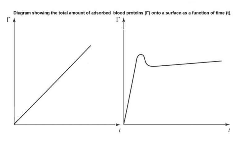
Importance for Biomaterials
Why does protein adsorption matter so profoundly for biomaterials? It dictates the initial and long-term biological response, influencing several critical outcomes:
Immune Activation & Foreign Body Response: Adsorbed proteins can be recognized as foreign, triggering inflammatory responses and potential immune rejection of the biomaterial. If proteins like Immunoglobulins (IgG) or Complement proteins adsorb in high concentrations and undergo the "structural changes" we discussed, they can signal the immune system. The "foe" signal: When these proteins unfold, they expose "cryptic" sites that macrophages recognize as a signal to attack. The Result: Chronic inflammation, leading to a thick fibrous capsule (a layer of dense connective tissue that forms around something the body wants to isolate or protect itself from) around the device that can isolate it from the body (making it fail, for example, if it's a drug-delivery patch or a glucose sensor).
Thrombosis: Certain adsorbed proteins, like fibrinogen, can initiate blood clotting pathways, leading to device obstruction or failure in cardiovascular applications. For cardiovascular devices like stents or heart valves, the protein layer is a life-or-death matter. Fibrinogen: As a "SOFT" (flexible structure, easily change shape [unfold] when they adsorb to a surface, less internally stable) protein that often wins the Vroman race, its adsorption can trigger the coagulation cascade.
Cell Adhesion: The adsorbed protein layer forms the new interface that host cells interact with, dictating their attachment, migration, growth, and differentiation. => On positive side, protein adsorption is required for healing. The Anchor: Proteins like fibronectin and vitronectin contain RGD peptide sequence. If these proteins adsorb in the correct orientation, tissue cells CAN BIND TO THEM and begin the process of osseointegration - growing bone directly onto the implant surface!!
Tissue Integration: Ultimately, the composition and conformation of the adsorbed protein layer govern how well the biomaterial integrates with the surrounding host tissue.
As the first biological event upon implantation, protein adsorption sets the stage for all subsequent interactions and the overall success or failure of the medical device.
Note: Hard proteins = rigid and compact, resist unfolding when adsorbing.
Engineering Surface Properties
Strategies to control protein adsorption are crucial for optimizing biomaterial performance and biocompatibility.
Hydrophilic Coatings: These coatings create a strong water-rich layer at the biomaterial surface, effectively repelling proteins by minimizing favorable hydrophobic interactions and maintaining a hydration shell.
Zwitterionic Surfaces: Designed with balanced positive and negative charges, zwitterionic surfaces form tightly bound hydration layers, which mimic biological membranes and effectively resist protein adhesion.
PEGylation: Grafting polyethylene glycol (PEG) polymer BRUSHES onto the surface creates a steric barrier. This physically hinders proteins from reaching the surface and forming stable adsorption bonds.
Nanotopography: Precise engineering of surface roughness at the nanoscale can physically block protein adsorption or guide their orientation and conformation, thus influencing interaction strength and cell response.
The ultimate goal of these advanced surface engineering approaches is to meticulously control both the identity and conformation of proteins that interact with the biomaterial, thereby dictating the desired biological outcome.
Thermodynamics of Protein Adsorption Resistance
Antifouling (preventing the unwanted buildup of materials on a surface, especially biological substances) surfaces are engineered to thermodynamically disfavor protein binding — by maximizing surface-water affinity (by making a surface super hydrophilic => energetically expensive for a protein to push the water molecule out of the way) and minimizing protein-surface interactions (neutral charged surface [minimize electrostatic attractions] or by using steric hindrance like PEG chains!).
Strategy: Hydrophilic Coatings (PEGylation): Polyethylene glycol (PEG) chains form a dense hydration layer. Displacing this layer to adsorb a protein costs significant free energy — making adsorption thermodynamically unfavorable.
Strategy: Zwitterionic Surfaces Equal positive and negative charges create an ultra-strong, tightly bound hydration shell via electrostriction (when a material slightly changes shape when exposed to an electric field) (the zwitterionic molecules have equal positive and negative charges; they bind water via very strong ionic-dipole interactions rather than just hydrogen bonding!). Protein adsorption is entropically and enthalpically penalized — among the most effective antifouling strategies known.
Cath-1 (image) = an example of an antifouling surface.
![<p><strong>Antifouling (preventing the unwanted buildup of materials on a surface, especially biological substances) </strong>surfaces are engineered to thermodynamically disfavor protein binding — by maximizing surface-water affinity (by making a surface super hydrophilic => energetically expensive for a protein to push the water molecule out of the way) and minimizing protein-surface interactions (neutral charged surface [minimize electrostatic attractions] or by using steric hindrance like PEG chains!). </p><p>Strategy: Hydrophilic Coatings (PEGylation): Polyethylene glycol (PEG) chains form a <strong>dense hydration layer</strong>. Displacing this layer to adsorb a protein costs significant free energy — making adsorption thermodynamically unfavorable.</p><p>Strategy: Zwitterionic Surfaces Equal positive and negative charges create an ultra-strong, <strong>tightly bound hydration shell </strong>via electrostriction (when a material slightly changes shape when exposed to an electric field) (the zwitterionic molecules have equal positive and negative charges; they bind water via very strong ionic-dipole interactions rather than just hydrogen bonding!). <strong>Protein adsorption is entropically and enthalpically penalized — among the most effective antifouling strategies known.</strong></p><p>Cath-1 (image) = an example of an antifouling surface. </p>](https://assets.knowt.com/user-attachments/da499417-eff6-47c4-8e28-ebf660e453fe.png)
Key Takeaways: The Interplay of Forces
Thermodynamics & Kinetics: While thermodynamics tells us if a reaction can happen (spontaneity), kinetics tells us how fast it happens. Thermodynamics (DeltaG): Adsorption is generally spontaneous (DeltaG < 0). This is often driven by an increase in entropy (DeltaS) because water molecules structured around the protein and the surface are released into the bulk solution when the protein binds. Kinetics: This involves the arrival rate of proteins at the surface, often governed by diffusion. The "Vroman Effect" is a classic kinetic example where smaller, more abundant proteins arrive first but are eventually replaced by larger proteins with higher binding affinities.
Surface Chemistry Dictates Forces: The "flavor" of the surface determines which intermolecular forces dominate the interaction: Hydrophobic Surfaces: Adsorption is largely driven by the hydrophobic effect. Proteins will often unfold to bury their hydrophobic cores against the surface. Charged/Hydrophilic Surfaces: Electrostatic interactions (Coulombic forces) dominate.
Conformational Flexibility ("Hard" vs. "Soft" Proteins): This is a critical distinction in how proteins maintain their "shape" upon landing: "Hard" Proteins: These have high internal stability (often due to disulfide bonds). They resist unfolding and tend to adsorb only if there is a STRONG ELECTROSTATIC ATTRACTION. "Soft" Proteins: These have low internal stability. They readily unfold (denature) on a surface, which increases their footprint and entropy, making them more likely to adsorb strongly even on surfaces that seem "unfavorable”!!!
Real-World Impact: These principles underpin the design of biomaterials, antifouling coatings (using PEG to create a surface that prevents protein adsorption by creating a physical and energetic barrier), chromatographic resins (chromatographic resins work because they are engineered surfaces that selectively adsorb proteins and then release them under controlled conditions for separation), and biosensor platforms (biosensor platforms rely on protein adsorption both to build the sensing layer and as a key process that can enhance or interfere with detection) (many biosensors work because proteins are deliberately adsorbed onto the sensor surface: antibodies adsorb onto gold, silica, polymers, etc.; enzymes are immobilized on electrodes; This creates the recognition layer).
Biomaterial Degradation in the Biological Environment
Complex Biological Environment: The body presents a unique environment characterized by neutral pH (~7.4), constant temperature, and aqueous media containing various ions.
Degradation Types: Biomaterials can undergo both uncontrolled degradation (leading to device failure) and controlled degradation (designed for tissue engineering and drug delivery).
Material Structure Impact: The structure of biomaterials directly influences their degradation patterns and resulting changes in material properties over time. Ex. Crystallinity (highly crystalline materials) degrade more slowly because their structure is tightly packed. M.W. => higher M.W. => slower degradation.
Inflammatory Response Effects: Local inflammatory responses can significantly alter the surrounding chemical environment, potentially accelerating material decomposition. Inflammation leads: release of enzymes, production of oxygen reactive species (ROS), local pH changes. These changes lead to => release of enzymes, alter degradation pathways, and cause unpredictable material behavior.
Understanding these factors is crucial for predicting in vivo degradation and ensuring biomaterial suitability for specific applications.
Degradation of Polymers
1.) Swelling/Dissolution: Water molecules are absorbed, reducing secondary bonding (like hydrogen bonds) between chains and thermal properties. If the chains are soluble enough, the polymer may dissolve completely in an aqueous environment. Think: when a polymer is placed in a biological (watery) environment, water molecules enter the material => this pushes the polymer chains part and weakens the secondary bonds => then, the material becomes weaker and softer; its thermal and mechanical properties decreases; if the polymer is highly water-soluble, it may completely dissolve (think of a sponge absorbing water - except at the molecular level).
2.) Chain Scission by Hydrolysis: Water molecules facilitate the cleavage of certain bonds within a macromolecule, and is a common degradation mechanism of condensation polymers. Chat: Hydrolysis means water breaks chemical bonds in the polymer chain. This is especially common in condensation polymers. Long polymer chains are cut into shorter segments; decreases strength and molecular weight.
3.) Chain Scission by Oxidation: Reactive species attack and BREAK COVALENT bonds, similar to addition polymerization, causing degradation that depends on the chemical domains within the macromolecule. Chat: In the body, reactive species (free radicals or oxygen) attack the polymer. These species break covalent bonds in the chain. What influences this? Chemical structure of the polymer, Presence of sensitive groups (some parts degrade faster than others), Results = weakening of the material, surface damage, and faster overall degradation.
Polymers degrade primarily through swelling/dissolution and chain scission via hydrolysis or oxidation, leading to discoloration, crazing (small cracks forming) or changes in mechanical properties. Factors such as water access, proteins, inflammatory cells, and mechanical stress influence the degradation rate. The breakdown of a polymer via these means is determined by the nature of each process.
Hydrolytic Degradation of Polymers
Hydrolytic Degradation of Polymers (where water molecules break the chemical bonds in a polymer, leading to the gradual breakdown of its structure => one of the most important mechanisms for biodegradable polymers!
Picture to the left = Ester Hydrolysis Reaction! Ester is the left molecule!
Ex. General Ester Hydrolysis Example: PGLA Degradation: In polymers like PGLA, chain scission produces lactic acid and glycolic acid. Key point: Both are weak acids (pka = 3.8). As they accumulate, they lower the local pH.
1.) Ester Bond Cleavage: Water attacks the ester linkage (-C(=O)-O-), breaking the polymer backbone. Key Reaction! Many biodegradable polymers like PGLA contain ester bonds in their backbone.
2.) Carboxylic Acid Formation: Chain scission generates -COOH and -OH end groups, INCREASING local acidity.
3.) Autocatalytic pH Drop (POSITIVE FEEDBACK LOOP): Accumulated -COOH groups DONATE H+, lowering local pH and accelerating further hydrolysis - a positive feedback loop.
Clarification: Autocatalytic pH Drop: Hydrolysis produces acidic end groups, these groups release H+ ions, local pH decreases (becomes more acidic), acidic conditions SPEED UP hydrolysis, faster hydrolysis produces MORE acid! => this self-accelerating cycle is called auto-catalysis!
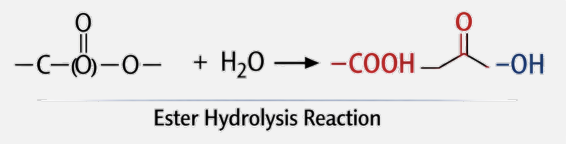
Poly(α-hydroxy acid) Implant Erosion
Poly(α-hydroxy acid) => a class of biodegradable polymers made from α-hydroxy monomers. Important polymers in this family include: PLA, PGA, and PLGA (a copolymer of lactic acid and glycolic acid). Key Properties: They degrade into natural metabolites: lactic acid (enters metabolism) and glycolic acid (further processed/excreted).
PLA and PGA degrade inside the body! These polymers = biodegradable and break down in the body into HARMLESS products! PLA => lactic acid. PGA => glycolic acid! => makes them useful for medical implants like sutures, drug delivery systems, and bone devices.
Polylactide: semi-crystalline (elastic = 2.7 GPa) (moderately stiff), hydrophobic, degrades to lactic acid, applications in drug delivery potential. Chat: Less hydrophobic than polyglycolide, so it degrades slower!
Polyglycolide: higher crystallinity (E = 7. GPa) (higher stiffness), hydrophilic, degradable sutures, degrades to glycolic acid, applications = bone pins. Think polyglycolide = guppies = fish! higher crystallinity = stronger but hydrophilicity allows faster water uptake => speeding degradation!
Picture: crystalline regions = tightly packed => resist water penetration! loosely packed = water enters easily! degradation starts in amorphous regions first!
Bottom Left Graph: Effect of composition shows degradation time versus %PLA in a PLA-PGA copolymer. Middle composition degrades the FASTEST => Why? Mixing PLA and PGA disrupts the crystallinity, creating MORE amorphous regions => faster breakdown! Engineers tune PLA/PGA ratios to control how long an implant lasts!
Right Graph: Crystalline PLLA (black) = very slow degradation; PGA-co-PLA 90/10 = very rapid degradation (reminder: mixing PLA and PGA disrupts the crystallinity, creating more amorphous regions => faster breakdown!). Inion OTPS 2.0 mm plate (Blue line): This represents a commercial orthopedic device. It maintains strength for about 25 weeks (the "lateau") before undergoing a more rapid loss of mass, likely designed to provide support during bone healing and then resorb.
Some More on Right Graph from Gem: At the extremes (0% or 100% PLA), the polymers (Pure PGA or Pure PLLA) are highly crystalline and take months or years to degrade. At an intermediate ratio (around 50/50 PLGA), the material becomes nearly 100% amorphous because the alternating monomers "confuse" the chain and prevent folding. This results in the lowest possible degradation time (the "trough" of the curve).
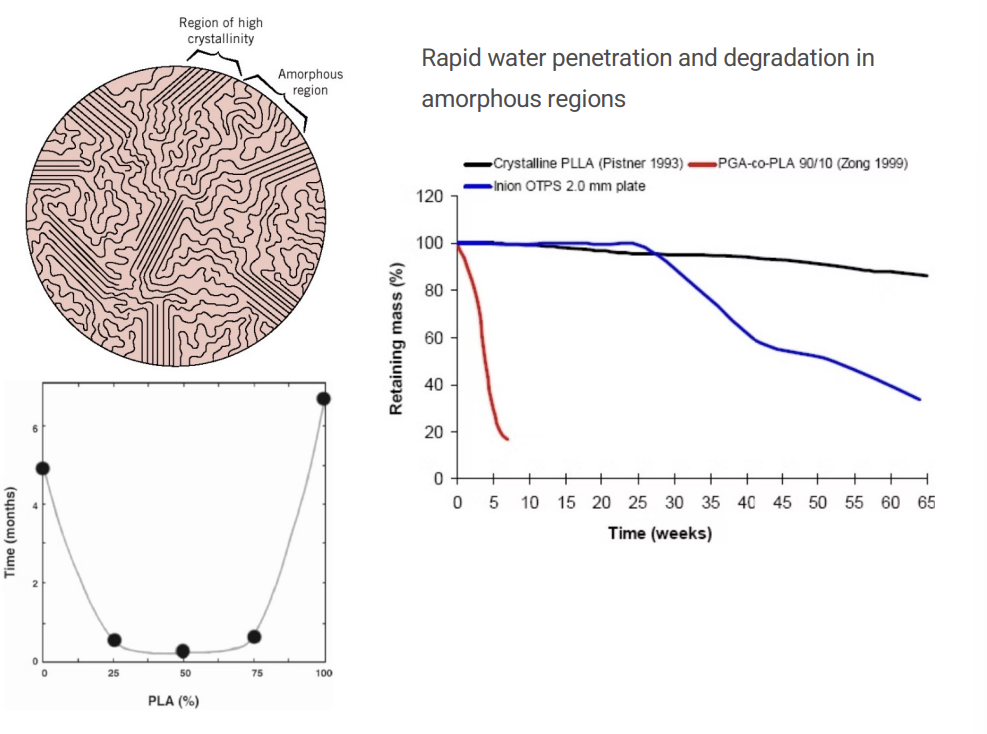
Degradable Polymers
Degradable Polymers => common materials = PGA, PLA, PDO, and copolymers (mixtures of the above).
Multifilament braids (FASTER DEGRADATION) => braided structures. Ex. decron, vicryl, polysorb, typical PGA or PGA/PLA copolymers; properties = flexible and easy to handle, faster degradation, higher SA (more water penetration). Ex. vicryl = ~90% PGA/10% PLA => balanced strength and moderate degradation rate.
Monofilaments (SLOWER DEGRADATION) => exs. PDS II, maxon, etc. Made from PDO or COMPLEX copolymers. Properties: smoother (less tissue drag), slower degradation, and lower infection risk.
Right Image PGA => PGA fibers: original (2 to 5 weeks), rapid structural breakdown, fibers become fragmented quickly. Think: guppies = hydrophilic = degrade faster than PLA. PLA fibers => much slower change. Still relatively intact after 5 weeks. Confirms: PGA degrades faster than PLA.
Graph on Bottom: Strength versus Weight Loss: Strength is lost before the material fully degrades. Why? Polymer chains break (loss of mechanical integrity), but mass is still present until the fragments dissolve. Picture: tensile strength decreases rapidly. Weight loss later increases.
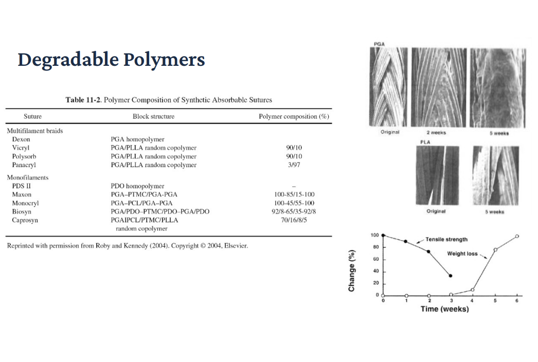
Mechanisms of Release
Drug release depends on how the polymer erodes. Surface erosion = controlled, steady- delivery. Bulk-erosion = fast, less predictable release. Surface erosion => degradation happens layer by layer from the outside. The core stays intact until exposed. What happens: Drug is released gradually as the surface erodes. Thickness decreases over time! Graph: release rate dC/dt is constant => flat line => called zero-order release (ideal for medicine); good for steady drug levels in the body, avoid spikes or overdosing!
Problem: Zero-order release best obtained from surface-eroding devices, but polymers with surface erosion!
Bulk Eroding: BIG initial spike (burst release) then decreasing release over time! Can exceed toxic dose. Water penetrates the entire system. First degradation happens throughout the whole material at once. What happens: Drug is trapped initially. Then, suddenly releases.
Image: Poly(anhydride) Implant: a classic example of a surface eroding material. Aliphatic (category of hydrocarbons where carbon atoms are joined together in straight chains, branched chains, or non-AR rings) segments: Degrade within days, providing the initial “drive” for erosion. Aromatic segments: degrade over years, providing the structural stability needed to slow the overall process down.
More clarification: Surface Erosion (slow water penetration, stays on the outside); shape gets smaller but keeps its shape; polyanhydrides; release is predictable and constant. Bulk Erosion: Fast water penetration (soaks the whole thing), shape stays the same size but gets hollow or soft, PLA, PGA, PLGA (release is often fast at first and then unpredictable). Drug Release for Bulk Erosion: as the internal surface crumbles, you often get a massive burst of drug all at once because the “walls” holding the drug in are failing everywhere.
Top Schematics: Left Side: Surface-Eroding Matrix: In the second frame, the gray box has shrunk in size; left portion is gone; Water is unable to penetrate the interior. It can only react with the molecules on the very surface. As those molecules break off (erode), the drug molecules that were trapped there are "liberated" and released! The drug in the center of the box remains perfectly dry and protected until the erosion front actually reaches it. This is why the release is so steady; you release a constant amount of drug for every millimeter of polymer that "melts" away.
Right Side: Bulk-Eroding Matrix: In the second frame, the gray box is still the EXACT same size as the first frame, but notice the teal dots on the far left. They are now in a white area, even though the "box" hasn't shrunk yet. Water has rushed into the entire structure. It is breaking the polymer chains in the middle, the back, and the front all at the same time yet. The polymer is becoming MORE POROUS and "Swiss-cheese-like." The drug is released because it can now diffuse through the water-filled pores that have formed inside the matrix. The device will eventually crumble all at once, but it doesn't necessarily get smaller in dimensions until the very end of its life.
More Chat: Surface Erosion is generally preferred because the dosage is predictable. If 10% of the thickness is gone, 10% of the drug is gone. Bulk Erosion is more common (materials like PLA/PGA) but harder to control. There is a risk that after a few weeks, the entire structure becomes so weak that it "dumps" the remaining 50% of the drug in a single day, which could be toxic.
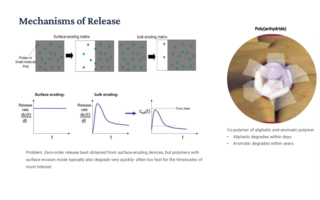
Additional Factors in Polymer Degradation
Environmental Stress Cracking: Tensile stresses in the biological environment causes the EXTERIOR of the implant to develop deep cracks perpendicular to the primary loading axis. Inflammatory cells are required before environmental stress cracking will occur. More Clearer: Environmental Stress Cracking: Cracks form on the surface of the implant due to mechanical stress and biological environment. How: the implant is under tensile (pulling) stress, body fluids, and biological activity weaken the structure! Deep cracks form PERPENDICULAR to the load direction! More (Gemini): For ESC to happen, you need tensile stress (the material being pulled apart) and a specific chemical environment. The Biological Trigger: The slide notes that inflammatory cells (like macrophages) are required (this is because that act as the chemical catalyst that initiates the crack!). These cells settle on the polymer surface and release reactive oxygen species or other chemicals. The Result: These chemicals weaken the polymer chains. Because the material is under stress, deep cracks begin to form perpendicular to the direction of pull.
Enzyme-Catalyzed Degradation: Enzymes are catalysts, LOWERING the required activation energy for specific reactions. Some can cause hydrolytic or oxidative degradation of synthetic polymers.
Beyond primary degradation mechanisms, mechanical stress and specific proteins can facilitate polymer dissolution. Enzymes present in surrounding tissue also contribute by catalyzing bond cleavage. Variability in enzyme production makes predicting enzyme-catalyzed degradation challenging. An understanding of these elements is essential for predicting the degradation response for a given material.
Degradation Mechanisms Across Material Classes
Polymers (PGA, PLA, etc. => remember, these are bulk-eroding and biodegradable polymers; mixing PGA and PLA often leads to disruption of crystallinity and faster degradation than pure PGA or PLA) (they are multifilament degradable polymers). Primary Mechanisms: Chain scission (hydrolysis, oxidation), Swelling & dissolution, Surface & bulk erosion. Driving Factors: Water penetration, local pH (remember hydrolysis causing acidic end groups can release protons, leading to local pH drop, which speeds up hydrolysis and leads to a further pH drop [autocatalysis]), Crystallinity, enzyme activity. Timescale: Weeks to years.
Metals: Primary Mechanism: electrochemical corrosion (oxidation [metal LOSES electrons], reduction). Driving factors: galvanic coupling (contact between different metals accelerates corrosion), passivation failure (passivation layer = protective oxide layer [if it breaks, it leads to rapid corrosion]), mechanical loading (stress can crack protective layers), and biological environment. Timescale: months to decades (think of a hip implant); acute if passivation fails!
Ceramics (degrade by dissolving or cracking): Primary Mechanism: Dissolution (e.g. calcium phosphates [bone-like materials]), slow crack growth (cyclic loading) (tiny cracks grow under repeated stress; happens under cyclic loading such as walking or chewing), phase transformation (e.g., zirconia aging) (some ceramics change crystal structure over time; ex. when zirconia ages, the transformation weakens the material, which can lead to cracking or failure). Driving Factors: Solubility, grain size (smaller grains = more surface area exposed to the environment => faster degradation), porosity (more PORES = more fluid penetration = faster degradation), pH (more acidic => speeds degradation). Timescale: rapid (resorbable) to extremely slow (inert). Ceramics are often used for bone repair (calcium phosphates are chemically similar to bone, bioactive, and resorbable [gradually dissolve and get replaced by bone]). Ceramics are also often used for wear-resistant implants (ex. zirconia and alumina), these are hard, low friction, and highly wear-resistant. They are used in hip joint replacements (femoral heads), dental implants, and joint surfaces.
Corrosion of Metals and Ceramics
Corrosion is an electrochemical process involving electron transfer through oxidation and reduction reactions. Oxidation generates electrons at the anode (AN OX = loss of electrons at the anode [aka metal atoms are oxidized at the anode [releasing electrons]) (OR: an OX LOSES [in a battle]), while reduction consumes them at the cathode (FAT RED CAT = reduction is where gains [or CONSUMES] electrons at the cathode). For a metal M with n valence electrons, oxidation is represented as M → M^n+ + ne (will lose or release electrons).
Metals are generally more susceptible to degradation than ceramics in physiological fluids due to their electrochemical nature. Think: Ceramics like alumina or zirconia are ionic or covalent solids; they are ALREADY IN A CHEMICALLY STABLE, oxidized state, they do not easily exchange electrons, so in physiological fluids, they don’t form electrochemical cells easily, and they do NOT easily exchange electrons. Corrosion involves ion leaching, potentially causing biological consequences. Characterization is vital for predicting structural changes, failure, and biocompatibility.
Half-Cell Potentials: Standard reduction potentials rank metal oxidation behavior relative to a STANDARD HYDROGEN ELECTRODE. Metals with more negative potentials are more active (ANODIC). The galvanic series (galvanic series rank metals based on their corrosion behavior in environments like seawater; important in real-world conditions like physiological fluids in the body) (when two metals are connected, the more active metal [anode] corrodes and the less active metal [cathode is protected] => this is called galvanic corrosion] derived from metal corrosion in seawater, indicates relative activity in saline solutions, similar to bodily fluids.
![<p>Corrosion is an electrochemical process involving electron transfer through oxidation and reduction reactions. <strong>Oxidation generates electrons at the anode (AN OX = loss of electrons at the anode [aka metal atoms are oxidized at the anode [releasing electrons]) (OR: an OX LOSES [in a battle])</strong>, while <strong>reduction consumes them</strong> at the cathode (FAT RED CAT = reduction is where gains [or CONSUMES] electrons at the cathode). For a metal <em>M</em> with <em>n</em> valence electrons, <strong>oxidation </strong>is represented as M → M^n+ + <strong>ne</strong> (will lose or release electrons). </p><p>Metals are generally more susceptible to degradation than ceramics in physiological fluids due to their electrochemical nature. Think: Ceramics like alumina or zirconia are ionic or covalent solids; they are ALREADY IN A CHEMICALLY STABLE, oxidized state, they do not easily exchange electrons, so in physiological fluids, they don’t form electrochemical cells easily, and they do NOT easily exchange electrons. Corrosion involves ion leaching, potentially causing biological consequences. Characterization is vital for predicting structural changes, failure, and biocompatibility.</p><p>Half-Cell Potentials: <strong>Standard reduction potentials rank metal oxidation behavior relative to a STANDARD HYDROGEN ELECTRODE</strong>. Metals <strong>with more negative potentials are more active (ANODIC)</strong>. The galvanic series (galvanic series rank metals based on their corrosion behavior in environments like seawater; important in real-world conditions like physiological fluids in the body) (when two metals are connected, the more active metal [anode] corrodes and the less active metal [cathode is protected] => this is called galvanic corrosion] <strong>derived from metal corrosion in seawater</strong>, indicates relative activity in saline solutions, similar to bodily fluids.</p>](https://assets.knowt.com/user-attachments/b644adc5-ce0b-42c7-b465-6f4e46f4780f.png)
Electrochemical Corrosion
Ex: consider the corrosion of zinc in an acid solution:
Oxidation => (AN OX LOSES) => Zn loses or releases two electrons at the anode.
Reduction => (FAT RED CAT) => 2H+ + 2e- → H2 (gas). At the cathode, reduction occurs, where electrons are consumed or gains (here, by 2H+).
Other possible reduction reactions (with oxygen): If oxygen is present, different reduction reactions can occur: in acidic solution, O2 + 4H+ + 4e^- → 2H2O. In neutral/basic solution, O2 + 2H2O + 4e^- → 4OH-. These reactions can replace hydrogen formation and still drive corrosion!
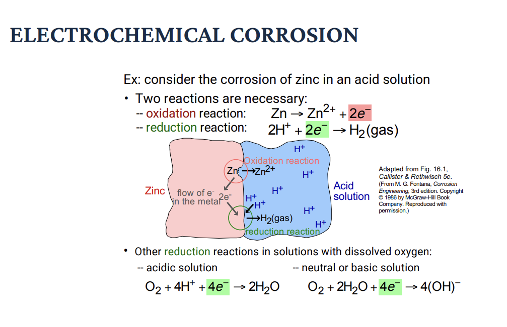
Corrosion of Metals
Moving down the list = increasing tendency to corrode! Think: AN OX loses: oxidation reaction happens at the anode (where metals loses electrons). For example, at the top, Au is very stable (rarely corrodes). At the bottom, K is extremely reactive (most negative V0metal). Left = EMF series = a list of metals arranged by their standard electrode potential (V0). The top = more positive V0 => the more cathodic (less likely to corrode). The bottom = more negative V0 = more anodic (more likely to corrode) => the metal with the LOWER (more negative) potential (V0 metal) corrodes! => why? If it more easily loses electrons => undergoes oxidation => exactly what corrosion is.
Potential of Cd is less than Ni, so Cd corrodes. Cell behavior. Electrons flow from Cd → Ni. Cd dissolves into solution as Cd2+. Ni remains intact! The voltage difference deltaV0 = 0.153 V is the driving force for the reaction! Insight: Corrosion = a galvanic (electrochemical) process. When 2 metals are connected, the more anodic metal sacrifices itself. The more cathodic metal is protected.
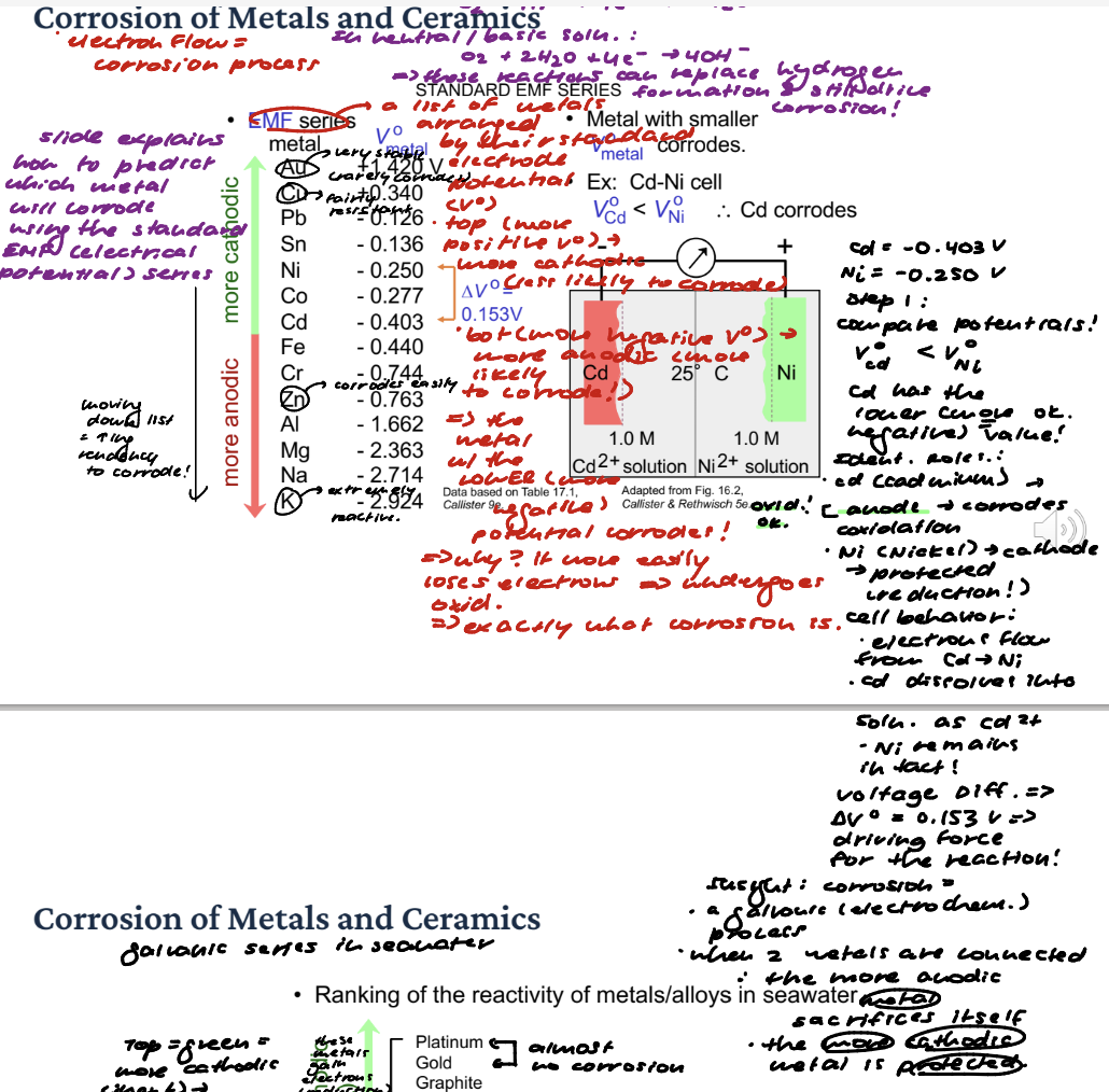
Corrosion of Metals
Galvanic Series in Seawater => ranking of the reactivity of metals/alloys in seawater. 316 SS (passive) (passive = protected by a thin oxide layer => behaves more cathodic) is protected by an oxide layer. Similar to the EMF series, the more anodic = oxidation occurs, and the more cathodic metal = protected. Think if Steel is connected to Zinc in seawater, Zn (lower) (more anodic) corrodes and steel (higher) is protected! => used in galvanization (process of protecting iron or steel from corrosion by coating it with zinc) and sacrificial anodes (a piece of more reactive metal s attached to a metal structure to prevent it from corroding).
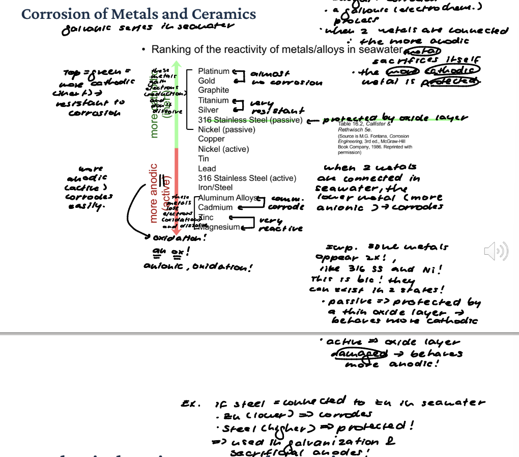
Mechanical Environment and Corrosion
Stress and Galvanic Corrosion: BENDING a metal causes the tensile side to be ANODIC (more reactive; more prone to oxidation), promoting galvanic corrosion (the accelerated corrosion of the more reactive, anodic metal when it is in contact with a more noble, cathodic metal in an electrolyte; aka corrosion caused by galvanic coupling) (reminder: galvanic coupling: when two dissimilar metals are connected in the presence of an electrolyte like water or saltwater).
Stress Corrosion Cracking: Occurs under tension in a corrosive environment, forming cracks PERPENDICULAR to stress. Failure can occur suddenly even if stress is not very high => metal can break unexpectedly.
Fatigue Corrosion (when a material is weakened by repeated loading cycles [cyclic stress]): Disrupts the passivating film, exposing the underlying surface and leading to corrosion.
Clarification: Galvanic Corrosion: When you bend a metals, the stretched (tensile) side becomes more anodic. The other side becomes more cathodic => this creates a tiny galvanic cell within the same metal. Result: the tensile side corrodes faster (think AN OX => anode = oxidation).
![<p>Stress and Galvanic Corrosion: BENDING <strong>a metal causes the tensile side to be ANODIC</strong> (more reactive; more prone to oxidation), promoting <strong>galvanic corrosion</strong> (the accelerated corrosion of the more reactive, anodic metal when it is in contact with a more noble, cathodic metal in an electrolyte; aka corrosion caused by galvanic coupling) (reminder: galvanic coupling: when two dissimilar metals are connected in the presence of an electrolyte like water or saltwater).</p><p>Stress Corrosion <strong>Cracking: </strong>Occurs under tension in a <strong>corrosive environment,</strong> forming cracks PERPENDICULAR to stress. Failure can occur suddenly even if stress is not very high => metal can break unexpectedly. </p><p><strong>Fatigue Corrosion (when a material is weakened by repeated loading cycles [cyclic stress]):</strong> <strong>Disrupts the passivating film, exposing the underlying surface and leading to corrosion</strong>.</p><p>Clarification: Galvanic Corrosion: When you bend a metals, the stretched (tensile) side becomes more anodic. The other side becomes more cathodic => this creates a tiny galvanic cell within the same metal. Result: the tensile side corrodes faster (think AN OX => anode = oxidation). </p>](https://assets.knowt.com/user-attachments/6c17f4e5-4d69-4668-85f4-0b2da614ea02.png)
Biological Environment and Corrosion
Protein Attachment: Alters the passive layer, REDUCING oxygen diffusion and oxide layer stability. They ALSO act as electron carriers (can FACILITATE corrosion reactions) and consume corrosion reaction products (shifts equilibrium => promotes MORE corrosion!). Clarification: The oxide layer on a metal needs a constant supply of oxygen from your blood to "heal" itself if it gets scratched. Proteins are large, bulky molecules. When they adsorb (attach) to the surface, they form a dense "carpet." This carpet acts as a physical barrier that slows down oxygen diffusion to the metal surface. Without enough oxygen reaching the surface, the metal can't maintain its protective oxide coating. The "passive" layer becomes "active," meaning the raw metal underneath is now exposed to the salty, corrosive environment of your body. “Acting as Electron Carriers”: Corrosion is an electrochemical process—it involves the movement of electrons from the metal (anode) to an electron "sink" (cathode) . Facilitated Transport: Some proteins contain metallic ions or specific chemical groups that can shuttle electrons. The "Bridge": Instead of the electron having to jump directly to a molecule in the fluid, the protein acts like a copper wire or a bridge. It accepts an electron from the metal and passes it along to an acceptor (like oxygen) further away. This "SPEEDS up" the electrical circuit of corrosion. “Consuming Corrosion Products (Le Chatelier's Principle)”: This is a bit of "chemical suction." When metal corrodes, it releases metal ions into the immediate area. Complexation: Proteins are excellent at grabbing onto these metal ions. According to basic chemistry, if you remove the products of a reaction, the reaction will speed up to try and create more. By grabbing and "pulling" the metal ions away from the surface, proteins keep the concentration of ions near the metal very low. This "sucks" more ions out of the metal, effectively dissolving the implant faster than it would in plain salt water. AKA proteins grabbing onto corrosion rection products shifts equilibrium to making more corrosion reaction products (AHA more corrosion occurs than would have if proteins not present).
Bacteria: Bacterial metabolism changes regional pH, affecting passive layer stability (passive layer is sensitive to pH changes; when bacteria changes pH, the passive layer can become unstable; once damaged, mor metal is exposed => more corrosion) and CONSUMPTION of hydrogen (drives corrosion reaction forward), thus encouraging anodic dissolution (metal corrosion happens when part of the metal becomes an anode; at the anode, metal atoms lose electrons and become ions => this is dissolution; anodic dissolution means: the metal is actively breaking down into ions and entering the environment) (makes sense => if we are driving corrosion forward, there will be more oxidation reactions at the anode [AN OX loses]; at the anode, metals lose electrons).
Inflammatory cells: Recruitment of inflammatory cells causes pH DROP and release of oxidizing agents, although oxidizing agents sometimes contribute to passive layer growth!!!
Chemical and cellular components of the biological environment can affect corrosion rates. Inflammatory responses, protein attachment, and bacterial presence can influence the stability of the passive layer and electrochemical potential. It's important to understand their affect on a metal before use in the body.
Controlling Metal Corrosion
Design and Fabrication: Mitigate stress-induced corrosion by minimizing stress raisers (stress raisers AKA stress concentrators = features in a material that cause stress to become higher in a small, local area compared to the rest of the material). For example, avoid sharp corners, notches => lead to stress corrosion and cracking. Select metal combinations close in the galvanic series to prevent galvanic corrosion (makes sense). Employ non-reactive metals or those forming passive oxide coatings.
Extra Processing Steps: Heat-treat stainless steels to reduce intergranular corrosion (PREVENTS weak regions along grain boundaries). Pretreat metals with nitric acid to form a passive surface layer before implantation!
Protective Layers: Apply metallic (gold, Ti), ceramic (oxides), or polymeric (plastics) coatings to provide a barrier between the active metal and its surroundings, thus decreasing dissolution of the implant (block contact with bodily fluids => slower corrosion!).
Reducing corrosion involves strategic implant (design and fabrication). Mitigation (taking actions to reduce the severity, impact, or likelihood of a problem or risk) can be achieved through material selection, processing and adding protective coatings to minimize dissolution of the implant in the body.
Pourbaix Diagrams in Corrosion
A Pourbaix diagram (also known as an E-pH diagram!!) is a graphical representation that shows the thermodynamic stability of different chemical species in an aqueous electrochemical system. It maps out stable regions of metals, ions, and oxides as functions of potential (E) AND pH. It helps predict corrosion behavior and passivation conditions.
3 Important States:
Immune State: Metal remains stable and won't corrode.
Passive State: Protected by oxide film formation. Ex. Iron forms Fe2O3 (rust layer in controlled form) => corrosion is slowed or stopped.
Active State: Corrosion occurs through metal dissolution. Metal dissolves into ions. Ex. Fe → Fe2+.
Example: Pourbaix diagram for iron in water showing regions of immunity (Fe), passivity (Fe2O3), and corrosion (Fe2+).
Pourbaix Diagrams in Corrosion
Pourbaix diagrams plot regions of corrosion, passivity, and immunity as a function of electrode potential and pH.
Corrosion: metal concentration > 10-6 M at equilibrium. Immunity (cathodic protection): equilibrium between metal and its ions at < 10-6 M. Chat: This condition can be achieved naturally or by cathodic protection, where the metal is forced to stay at a low electrochemical potential so it cannot oxidize. Passivity: equilibrium between metal and its reaction products (e.g. oxides) at concentrations < 10-6 M.
Left Diagram: Pourbaix diagram for an immune metal: golf. Gold = a noble metal; it mostly lies in the immunity region, meaning it doesn;t corrode easily. That’s why you see gold being used in jewelry.
Right => Chromium shows all 3 regions. Corrosion at high potentials. Passivation over a wide range. Immunity at low potentials. Diagram also overlays bodily fluids like gastric acid (acidic), saliva, intestinal fluid, and urine => shows chromium used in SS is safe in the body because it stays in the passive region, forming a protective oxide.
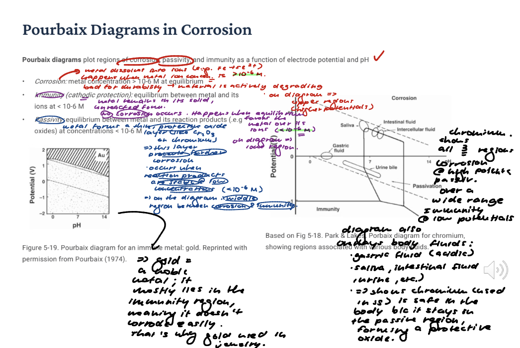
Factors Influencing Corrosion
Crevice Corrosion: Occurs in narrow, deep cracks due to oxygen DEPLETION and chloride ion diffusion (chloride comes from things like saltwater; as corrosion begins inside the crevice, metal ions accumulate inside; the solution inside becomes more positively charged; Once Cl- accumulates, they PENETRATE and disrupt the passivation oxide layer), ACCELERATING metal dissolution. Metals like stainless steel are more susceptible because it relies on a protective oxide layer (passivation). Low oxygen prevents this layer form reforming => more corrosion.
Pitting Corrosion: Results from flaws disrupting the passivation film, creating small anodes and large cathodes. It's dangerous due to localized material loss and potential undetected failure. Chat: Pitting Corrosion occurs at tiny defects on the metal surface: scratches, impurities, and weak spots in the oxide layer. Why > Small area loses its passive film. That spot becomes an anode (corroding site) => this crease a highly concentrated attack in one spot, deep pits that grow inward, and they are hard to detect (tiny surface openings); can cause sudden failure with little overall mass loss.
Intergranular Corrosion: Affects cast (to form a solid object by pouring liquid material into a mold and letting it solidify) devices with multiple grains, where grain boundaries act as ANODIC regions. Chromium depletion in stainless steel is a common example. Explanation: At grain boundaries: the structure is more disordered, atoms are less tightly bonded, and impurities often accumulate there. So grain boundaries become: easier sites for metal to dissolve (anodic behavior) (impurities disrupt metal-metal bonds: fewer strong metallic bonds, more brittle, unstable structure). SS resists corrosion because of chromium. Chromium forms a thin, protective oxide layer (Cr2O3). This is what gives SS its “stainless” property (passivation). Chromium carbides form at grain boundaries. This pulls out carbon out of nearby regions, so the areas become chromium-depleted zones.
Metal processing techniques and device design influence corrosion rates by creating microstructural variations, leading to localized ion concentration changes. Identifying and mitigating these factors can significantly improve implant durability.
Passivation: The Protective Oxide Layer
Passivation: Certain metals (Ti, Cr, Ni, stainless steels) spontaneously form a thin (2–10 nm), dense, adherent oxide layer when exposed to oxygen or water. This passive film acts as a kinetic barrier to further metal dissolution, protecting the underlying material. The film is self-healing: if scratched or disrupted, it reforms in milliseconds to seconds in an OXYGENATED environment.This explains why titanium and 316L stainless steel appear on BOTH the "passive" (noble) and "active" (reactive) positions in the galvanic series — the oxide film shifts their effective electrochemical potential.
When Passivation Fails: The protective passive layer can be compromised, leading to various forms of corrosion, especially in the harsh biological environment: Chloride ions (abundant in body fluids at ~150 mM) can locally PENETRATE or DESTABILIZE the passive film → pitting corrosion. Mechanical disruption (fretting [a type of surface damage that happens when two materials are pressed together and experience tiny repeated sliding motions], cyclic loading) can strip the film faster than it reforms → fatigue corrosion. Crevice geometries (e.g., screw-plate junctions) create oxygen-DEPLETED zones where the film cannot reform → crevice corrosion. Low pH from inflammatory response ACCELERATES film breakdown, particularly in infected sites.
Key Insight: Passivation is the single most important reason we can use reactive metals like titanium and chromium alloys inside the human body. Most corrosion failures in implants trace back to passivation breakdown.
Corrosion Prevention (i)
Materials Selection: Use metals that are relatively unreactive in the corrosion environment -- e.g., Gold or Au. Use metals that passivate (form a thin (5-10 nm, adhering oxide layer that slows corrosion).
Oxide layer acts as a shield, preventing further attack on the metal underneath!
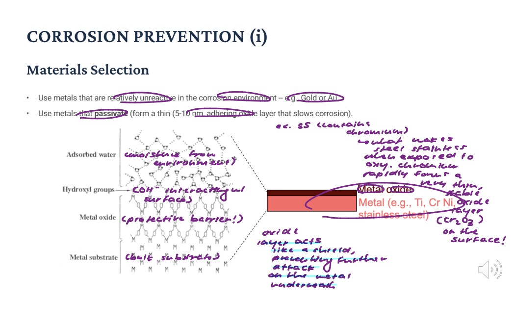
Corrosion Prevention (ii)
Add inhibitors (substances added to solution that decrease its reactivity): Slow oxidation/reduction reactions by removing reactants (e.g., remove O2 gas by reacting it w/an inhibitor!!!) (O2 is a key reactant in many cathodic reactions; if you remove O2, cathodic reaction cannot process) (think about earlier: in acidic and neutral or basic solution, oxygen reacted with electrons) (more accurately electrons are consumed in the cathodic reaction) and oxidation reaction by attaching species to the surface.
Cathodic (or sacrificial) protection: Attach a more anodic (more reactive, will oxidize or corrode) material to the one to be protected.
Galvanized steel is an example of cathodic protection: Zn is more reactive, so it oxidizes first. Zn protects the steel.
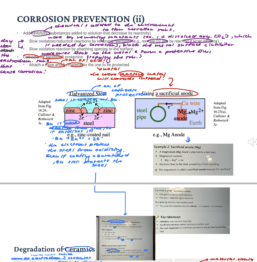
Degradation of Ceramics
1.) Dissolution: Calcium phosphate ceramics (hydroxyapatite, βTCP) dissolve in physiological fluids via chemical dissolution. Rate depends on: Ca/P ratio (more bone-like ration => slower, more stable degradation), crystallinity (amorphous ceramics => faster dissolution), porosity (more pores = more SA exposed => fluids can penetrate deeper => faster degradation), local pH (low pH / acidic => often increase dissolution). βTCP dissolves faster than HA due to lower thermodynamic stability. Clinically used in bone graft substitutes where controlled resorption is desired.
2.) Slow Crack Growth (Static Fatigue): Water molecules at crack tips in oxide ceramics (alumina, zirconia) cause stress-assisted bond breaking. Subcritical crack propagation under sustained or cyclic loading leads to delayed failure. Critical for load-bearing implants: femoral heads, dental crowns. Characterized by crack velocity vs. stress intensity factor (V-K) curves. Clarification: In oxide ceramics like alumina and zirconia, tiny cracks often ALREADY exist. At the tip of a crack (very end or front edge of a crack where it is actively growing or likely to grow), stress is highly concentrated (a stress raiser) and atomic bonds are stretched and weakened. When water is present: water molecules react with these stretched bonds. They help break bonds more easily (chemical assistance). This is called stress corrosion at the crack tip: stress + water = easier bond breaking! “Subcritical crack propagation”: Normally, a crack only grows when stress reaches a critical level (fracture toughness). But here: cracks grow below that critical stress very slowly over time. This is called: subcritical crack growth. So even if the load seems “safe”, the crack is still extending little by little. “Under sustained or cyclic loading → delayed failure”: (a) Sustained (static) load: constant stress over time; crack slowly grows => sudden failure later. (b) cyclic loading (fatigue): repeated loading/unloading, accelerates crack growth! Key idea: failure is delayed, not immediate. A component may appear fine for months or years, then suddenly fracture. Why this is critical in implants: In load-bearing medical ceramics like: hip implants (femoral heads) and dental crowns. These materials are strong but brittle and operate in a wet environment (body fluids = water). So: water-assisted crack growth is always possible!! Even small flaws can grow over time. “Crack velocity vs. stress intensity factor (V–K curves)”: Engineers study this using: K (stress intensity factor) → how strong the stress is at the crack tip. V (crack velocity) → how fast the crack grows A V–K curve shows: low K → very slow crack growth higher K → faster growth. near critical K → rapid fracture. This helps predict: how long a component will last and safe stress limits.
Phase Transformation (Aging): Yttria-stabilized zirconia (Y-TZP) undergoes tetragonal → monoclinic phase transformation in HUMID environments. Known as low-temperature degradation (LTD) or "aging". Causes surface roughening, microcracking, and strength loss. Accelerated by steam sterilization (uses hot, pressurized steam to completely kill mico-Unlike metals, ceramic degradation is not electrochemical — it is driven by dissolution chemistry, environmentally-assisted fracture, and phase instability.organisms) and body temperature exposure over years. Chat: Yttria-stabilized zirconia (Y-TZP) is widely used because it’s: very strong, tough for a ceramic, and used in hip implants and dental crowns. Its strength comes from a special crystal structure called the tetragonal phase. Zirconia can exist in different crystal structures (phases): Tetragonal → strong, stable (desired form) Monoclinic → weaker, less dense. Under certain conditions, it transforms: tetragonal → monoclinic. This transformation involves a volume expansion (~3–5%) and creates internal stresses. Why this happens in humid environments: Water (moisture) plays a key role. Water molecules penetrate the surface They react with the crystal structure. This destabilizes the tetragonal phase (why it happens in body fluids, steam, and humid air!!) “Low-temperature degradation”: It happens at relatively low temperatures (like body temperature ~37°C). It occurs slowly over time (years). Causes surface roughening (phase change starts at the surface, grains expand and push outward, and the surface becomes rough). Microcracking: volume expansion creates stress, and tiny cracks form between the grains. Strength Loss: cracks weaken the material. Can lead to reduced toughness and eventual fracture.
Unlike metals, ceramic degradation is not electrochemical — it is driven by dissolution chemistry, environmentally-assisted fracture, and phase instability.
Thermal Transitions & Biomaterial Degradation
Thermal Transitions
Applications: Impact on processing, sterilization, and long-term stability of biomaterials.
Clarification: Sterilization is a major "stability" hurdle for biomaterials. Many hospitals use Autoclaving (pressurized steam at 121 deg C). If a polymer has a Tg or Tm lower than 121 deg C, the heat from the autoclave will cause the implant to warp, shrink, or lose its structural "memory." Note: Higher than Tg => rubbery region! Lower than Tg => glassy region! So if a polymer has a Tg lower than 121 deg C, and we are at 121 deg C, the polymer is at higher than its Tg and its rubbery state! For materials with low thermal transitions (like some PLGAs), engineers must use alternative methods like Gamma Irradiation or Ethylene Oxide (EtO) gas, which don't require high heat.

Yellow; dashpot => viscous (no recovery)
Class: Under a constant load (creep test): a curve shows strain increasing linearly with time under constant stress; this means: deformation keeps increasing steadily. No leveling off. That behavior corresponds to a viscous or rubbery (viscoelastic fluid-like) state, where: polymer chains can move freely; chains can slide past each other continuously!! SO, strain keeps accumulating over time. Above Tg, the polymer is rubbery (below Tg, the polymer is glassy). That’s when creep becomes strong and continuous! In rubbery state: polymer chains are no longer locked, they slide, untangle, and rearrange. So under constant stress: deformation keeps increasing => linear creep. Linear strain vs. time => constant strain rate and viscous-like behavior => this is like honey flowing steadily under gravity! So, above Tg, polymer chains move freely, so the material behaves like a viscous fluid and shows steady, continuous strain increase (viscous creep) under constant stress.
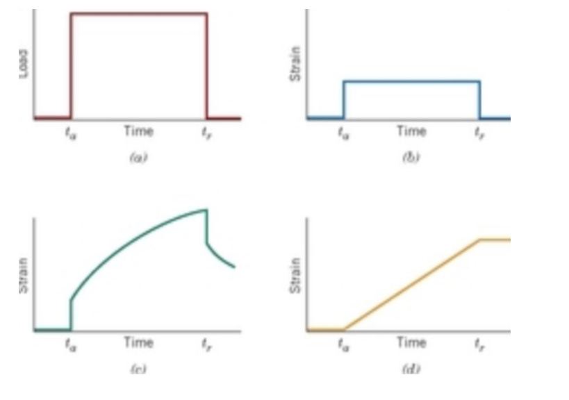
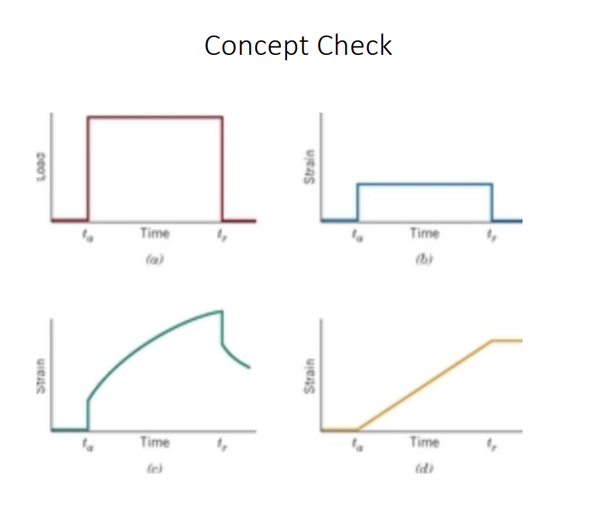
Concept Check: Testing your ability to identify how different types of materials respond to a sudden, temporary load. In MSE, we call this creep and recovery!
Red (a): At time ta, a constant load is suddenly applied and at time r, the weight is suddenly removed.
Blue (b): Purely Elastic Response: The instant the load is applied, the material stretches. The instant it is removed, it snaps back to exactly 0 strain. Key Feature: No time dependence. Strain graph = an exact copy of the load graph, it behaves like an ideal spring.
Green (c) : VISCOELASTIC response (Human Tissue or Biopolymers): How most biomaterials actually behave. Creep: When the load is applied at ta, there is an immediate ELASTIC JUMP, followed by a slow increase in strain over time. The polymer chains are slowly sliding past each other. Recovery: When the load is removed at tr, the material snaps back partway, but then takes its time "oozing" back toward its original shape. Key Feature: It shows delayed elasticity. It "remembers" the load for a while after it's gone. Clarification: creep = Elasticity (The Snap): When you put a heavy book on it, the shelf bows slightly. If you take the book off immediately, the shelf snaps back to being flat. CREEP (The Slow Sag): If you leave that heavy book there for three years, and then take it off, the shelf stays permanently bowed. Chat: Creep is when a material slowly and permanently deforms over time under a constant load, even if the load isn’t very high. Think: Constant stress + time => gradual deformation.
The weight wasn't heavy enough to "break" the shelf instantly, but because the weight was there for a long time, the internal molecules slowly slid past each other and "settled" into a new, deformed shape.
Yellow (d): Purely Viscous Response (e.g., Honey or Oil): This material has no "memory" and NO desire to return to its original shape. The Reaction: There is no instant jump. Instead, the strain increases at a constant, linear rate as long as the load is on (like pouring honey).The Result: When the load is removed at tr, the material just stops moving. It stays permanently deformed.Key Feature: Permanent deformation. It behaves like a "dashpot" (a piston in oil).

Green; Instant Jump at t0, when load is first applied, there’s a sudden increase in strain (that’s elastic deformation [instant, recoverable]), curved region (primary creep) (strain increases but the rate SLOWS down) (material is ADJUSTING INTERNALLY; polymer chains gradually rearrange and slide past each other over time under load, slope decreases over time); standard linear viscoelastic (look below for more viscoelastic models)
Class: Strain increases rapidly at first THEN it levels off. So, when the load is removed, strain recovers but not fully,; there is a time-dependent recovery and a kind of permanent deformation => viscoelastic behavior; what most polymers and soft tissues are going to be.
The graph shows time-dependent strain under load, followed by partial recovery when the load is removed => hallmark viscoelastic behavior.
![<p>Green; Instant Jump at t0, when load is first applied, there’s a sudden increase in strain (that’s elastic deformation [instant, recoverable]), curved region (primary creep) (strain increases but the rate SLOWS down) (material is ADJUSTING INTERNALLY; polymer chains gradually rearrange and slide past each other over time under load, slope decreases over time); standard linear viscoelastic (look below for more viscoelastic models)</p><p>Class: Strain increases rapidly at first THEN it levels off. So, when the load is removed, strain recovers but not fully,; there is a time-dependent recovery and a kind of permanent deformation => viscoelastic behavior; what most polymers and soft tissues are going to be.</p><p>The graph shows time-dependent strain under load, followed by partial recovery when the load is removed => hallmark viscoelastic behavior. </p>](https://assets.knowt.com/user-attachments/652386e9-d15b-469b-9c84-5b49aa808494.png)

Blue; Think: metals below their yield (similar to a spring)
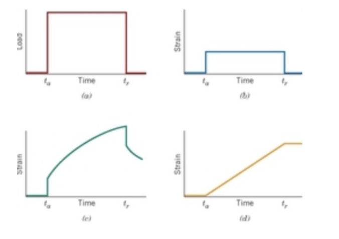

Tg of PS = 100 deg C and Tm = 240 deg C
So, at 70 deg C, we are below Tg, so PS is glassy. Crystalline => add even mor stiffness. Expected behavior => more elastic! Material is stiff, glassy, and brittle. Instant Recovery, no viscous flow, and no creep => Blue (b).
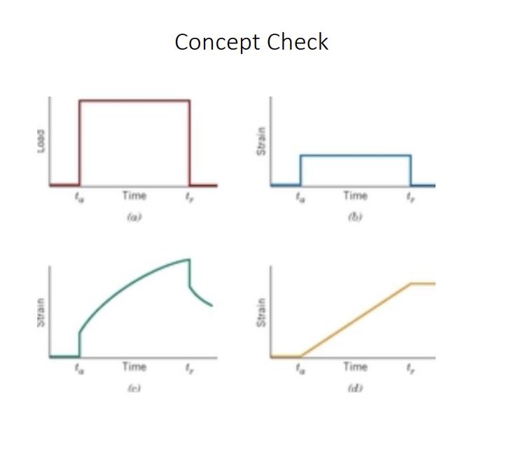
Interesting, Viscoelastic Related Models
Elastic Deformation: A recoverable Deformation; Viscous deformation: non-recoverable deformation.
Maxwell: Spring (elastic deformation) + Dashpot (viscous deformation) connected in series. When force is applied, there is an instant energy deformation due to stretching of spring. Further deformation takes place because of deformation of dashpot. When the force is removed, the spring returns to its original shape leading to recovery of the deformation. Model does not predict creep under constant stress condition ACCURATELY because this model suggest strain increase linearly with time. But, polymer mostly show strain RATE decreases with time. Good in understanding the deformation and recovery of SOFT SOLIDS like thermoplastic polymer in the vicinity of their melting point. Some More Clarification: Real viscoelastic materials: Do not keep deforming forever at a constant rate. Instead, they show: Primary creep (slowing down AKA strain rate is decreasing over time) Secondary creep (steady) Sometimes stabilization (in some materials). Maxwell shows unbounded deformation. But real materials: often slow down or resist deformation over time.
Kevin-Voigt: Spring and dashpot in parallel; Once force is applied, NO instantaneous deformation since the dashpot cannot deform instantaneously. At constant stress, the model is quite realistic as it predicts strain rate to decrease with time. So, model is EXTREMELY good for modelling creep in materials. BUT with regard to relaxation (after take off load), model is much less accurate. But, model can be used to predict the deformation behavior at LOW loading for ORGANIC polymers rubber and wood.
Standard Linear Viscoelastic (SLV) Model: Accurately describes BOTH the creep and the stress relaxation of a viscoelastic material.
Creep = time-dependent, gradual increase in strain (deformation) of a material subjected to a constant, sustained load. If a viscoelastic material is subjected to constant stress, it will show creep, which is a slow and continuous deformation over time!!
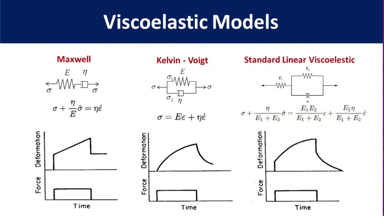

Tg of PS = 100 deg C and Tm = 240 deg C
At 180 deg C, we are above Tg but below Tm, so the polymer is rubbery. Amorphous => no crystalline regions. Chains are mobile, entangled, and free to flow. We expect the behavior to be more viscous flow, where strain increases LINEARLY with time but no recovery when unloaded; material flows almost like a viscous liquid => Yellow (d).
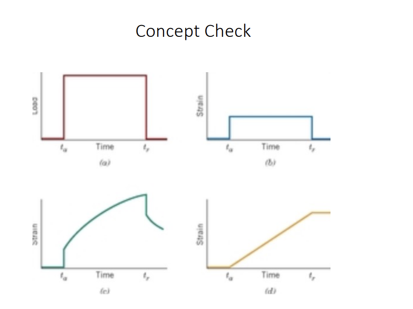
Tg of PS = 100 deg C and Tm = 240 deg C
At 180 deg C, we are in the rubbery region. Now we CROSSLINK some of those chains; crosslinks are covalent bonds. They cannot be broken by thermal energy below. at this temperature. So even though individual chains, segments or they're mobile, because we're above the glass temperature, that cross link network CAN’T flow because of those bumps. The chains stretched, and coil BETWEEN those cross links, but they can't permanently rearrange. Expected behavior => more viscoelastic!! Get some time-dependent deformation, but the chain segments BETWEEN the cross links are mobile and can REATTANGE, but the cross links prevent the viscous flow!!
Chat: Above Tg, chain segments gain mobility and can wiggle, rotate, and rearrange, so you get time-dependent deformation (creep-like behavior). BUT: crosslinks act like permanent anchors between the chains: they prevent the chains from sliding past each other permanently; they stop full viscous flow (no “liquid-like” behavior).
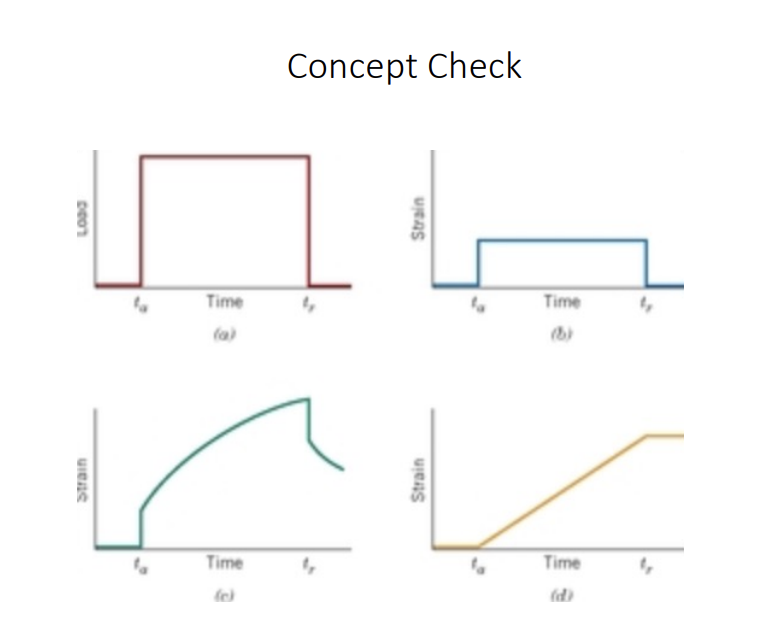

Tg of PS = 100 deg C and Tm = 240 deg C
At 100 deg C, we are AT glass transition behavior. Exactly at the TG or the glass transition, the amorphous chains are just beginning to gain mobility. So, some segments can move. Others are still frozen, and as a result, the material is transitioning, transitioning from glassy to the rubbery. So, you get a mixed structure: part rigid + part mobile at the same time. So, the expected behavior is viscoelastic = a mix of elastic response and viscous response that, you know, in this condition, the material creeps (material deforms over time), but it does so slowly. It also recovers, but it does so incompletely, not all the way. At Tg, stiffness also drops since material becomes much more softer (rubbery).
Thermal Transitions in Metals and Crystalline Ceramics
Reminder (unrelated): Viscoelastic materials exhibit an instantaneous elastic response and a time-dependent viscous response; creep is the gradual, time-dependent increase in strain under constant applied stress, resulting from the viscous component, and this is followed by partial, time-dependent recovery after unloading.
Crystalline materials (like most metals and ceramics) have atoms arranged in a highly ordered repeating pattern called a crystal lattice. Their behavior changes sharply at a key temperature: the melting point (Tm).
The characteristic thermal transition for crystalline materials is the melting point (Tm), the temperature above which the material's highly ordered structure breaks down!!
Liquid Behavior: Above Tm, the material behaves as a liquid and deforms via VISCOUS FLOW (INTERESTING!!!). Below Tm, the substance is a highly ordered solid, with its crystal structure and grain boundaries intact. Note: METALS AND CERAMICS can still show viscous flow, but only when they are in the LIQUID state. They do not behave like polymers, which can flow viscously while still being solid (above Tg). ALSO NOTE: CRYSTALLINE (ceramic/metal) => will not have Tg.
AMORPHOUS Ceramics (GLASSES): Thermal Transitions
No Distinct Tm: Glasses lack a distinct melting point (Tm). Instead, they become INCREASINGLY VISCOUS with DECREASING temperature until solid-like!!!! OH GENERALLY TRUE (even if not ceramic): Think: When you heat up honey, the viscosity decreases!
Defined Transitions: Thermal transitions are defined by VISCOSITY: Tm (eta= 100 P), the working point (eta = 104 P), and the glass transition temperature (Tg) are important for glass shaping.
Glass Transition (Tg): Below the glass transition temperature (Tg) the material is considered to be a glass (solid).
NOTE: AMORPHOUS (ceramic) => will have no Tm.
Thermal Transitions in Polymers
1.) Liquid, Rubbery Solid, or Glass: Polymers can behave as a liquid (above Tm), rubbery solid (above Tg), or glass (below Tg), depending on temperature and molecular structure. Crystalline polymers MELT at Tm, transitioning from ordered crystals to randomly ordered chains.
2.) Glass Transition (Tg): Amorphous polymers possess a glass transition point (Tg), generally LOWER than Tm. Below Tg, the material is glassy and brittle; above Tg, it is rubbery and elastic.
3.) Chain Flexibility: Factors INFLUENCING secondary bond formation, like branching (more branching => lower Tm since chains don’t pack efficiently => less crystallinity => lower Tm) and molecular weight impact Tm (APPARENTLY HIGHER M.W. typically INCREASES Tm; as chains get LONGER [higher Mw], there is more SA for van der Waals forces and hydrogen bonding to act between the chains; it takes more energy to shake these long, entangled chains out of their ordered, crystalline positions!). Chain flexibility and chemical constituents greatly affect Tg. Clarification: in many materials (especially polymers), chains are held together by primary bonds (strong covalent bonds WITHIN the chain and secondary bonds [weaker forces BETWEEN the chains] [van der Waals forces, dipole-dipole interactions, hydrogen bonding] [Melting Tm depends HEAVILY on how strongly chains stick together via these secondary bonds and how well they can pack]).
Melting & Glass Transition Temps
What factors affect Tm (controlled by how well chains pack + intermolecular forces) and Tg (controlled by how easily chain segments move => mobility / flexibility)? Both Tm and Tg increase with increasing chain stiffness! Chain stiffness is increased by presence of bulky side groups (think phenyl rings attached to backbone; reduce flexibility; increase in Tm since leads to BETTER ordered packing in some cases or stronger interactions!; increase in Tg since harder SEGMENT motion), polar groups or side groups (ex. -OH, -NH2, and -COOH) (create STRONG intermolecular attractions like hydrogen bonding and dipole-dipole interactions; result: chains stick together; Tg increases since MORE energy is needed for segment motion and Tm increases since MORE energy is needed to melt crystalline regions), chain double bonds and aromatic chain groups (increase in stiffness by restricting rotation along backbone so increases both Tm and Tg)!
Regularity of repeat unit arrangements – affects Tm only. Clarification: This refers to how ordered and consistent the polymer chain structure is, such as: Stereoregularity (tacticity): isotactic (all groups same side), syndiotactic (alternating), atactic (random), Regular vs irregular repeat placement along the chain Symmetry and ability to pack neatly.
Graph: The different lines represent how different types of structures expand:
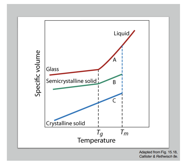
Diagram for Specific Volume vs. Temperature
Chat: Y-axis: Specific volume (how much space the material occupies). X-axis: Temperature (increasing to the right). Higher specific volume = material expands / becomes less dense.
Reminder: Crystalline materials: sharp melting at Tm. Amorphous (glass): gradual softening at Tg. Semicrystalline: combination of both behaviors (Tg + Tm).
Slope = Thermal Expansion. Steeper Slope => material expands more with heat. Solid => low expansion. Rubbery/liquid => higher expansion.
Note: Crystalline does not have a change in slope at Tg (there is no Tg for crystalline solids).
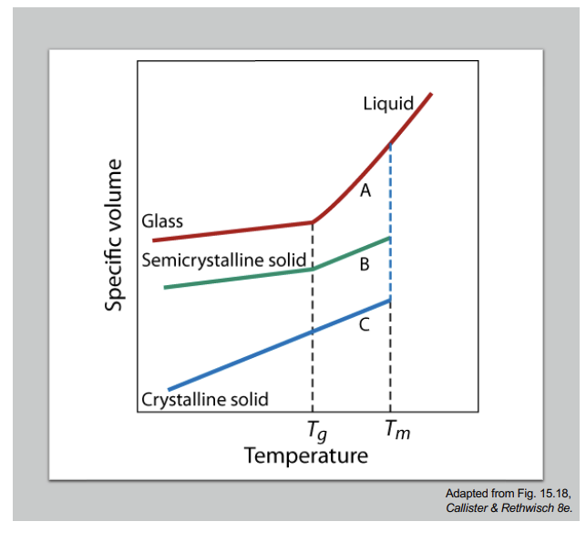
Polymer Crystallization and Annealing
Crystallization Temperature (Tc): At Tc, polymer chains gain sufficient energy (more accurately => enough molecular motion is still available for chains to move into ordered positions before they freeze completely) to move into a highly ordered crystalline state, an exothermic process. Chat: Tc is the temperature at which a polymer (or sometimes other materials) starts to form an ordered crystal structure while COOLING (Think: Trc). When a polymer is cooling from the melt: at high temperature, chains are random and mobile (liquid-like). As temperature drops, motion slows down. At Tc, polymer chains become able to align and pack neatly into an ordered structure (crystals). So, Tc is the point where crystallization begins during cooling.
Annealing: Annealing involves raising the temperature to Tc (at this temperature, chains are mobile enough to rearrange), MAINTAINING it for a time t (polymer chains slowly align and pack into crystals; crystallinity increases), and SLOWLY cooling. The Avrami equation describes the degree of crystallinity X(t). Annealing is a heat treatment used to INCREASE crystallinity and reduce internal stresses in a polymer.
Melting Temperature (Tm): Further heating ABOVE Tc leads to the melting temperature Tm, disrupting the crystal structure (remember: when heating temperature above Tm, the material's highly ordered structure breaks down).
The degree of crystallinity of the polymer developed at time t, X(t), is described by the Avrami equation as X(t) = 1 - e-ktn.
Thermal Analysis Techniques: DSC
Thermal Analysis: Thermal analysis techniques measure material properties as a function of temperature, providing insight into chemical and physical makeup. DSC is popular, revealing melting and glass transitions.
Differential Scanning Calorimetry (DSC) records the heat flow difference between a sample and reference as temperature changes. If the sample needs extra heat, it absorbs heat (endothermic); if it releases heat => it gives off heat (exothermic). Two types: power-compensated (sample and reference are kept at the same temperature; the instrument adjusts the power input separately to each; measures how much extra power is needed for the sample) ( how much more heating power does the sample need to match the reference?) and heat-flux DSC (sample and reference are places in the same furnace; both are heated together; measures temperature difference between them, and converts that into heat flow) (how differently does heat flow through the sample compared to the reference).
Graph: Endo = Up!
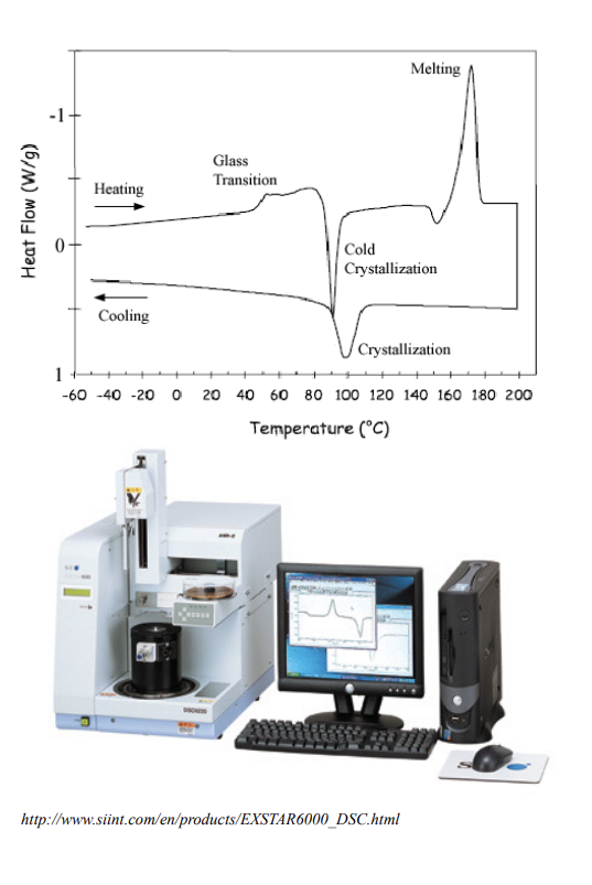
DSC: Instrumentation and Applications
Basic Components: DSC involves furnaces (part that controls temp), DSC sensors (measuring part), and a processor (converts raw sensor signals into heat flow data). It measures heat capacity changes at Tg and melting over a range at Tm, making it useful for polymers.
Percent crystallinity: DSC determines percent crystallinity by comparing the area under the Tm curve for semicrystalline and crystalline polymers. Also, both Tg and Tm can be determined via DSC.
Graph: Sample 1 (solid) and Sample 2 (dashed) have Tg and Tm. Area under the peak is higher for Sample 2, so it has a higher crystallinity.