6.2 ELECTRICITY:
1/44
Earn XP
Description and Tags
Electric charge is a fundamental property of matter everywhere. Understanding the difference in the microstructure of conductors, semiconductors and insulators makes it possible to design components and build electric circuits. Many circuits are powered with mains electricity, but portable electrical devices must use batteries of some kind. Electrical power fills the modern world with artificial light and sound, information and entertainment, remote sensing and control. The fundamentals of electromagnetism were worked out by scientists of the 19th century. However, power stations, like all machines, have a limited lifetime. If we all continue to demand more electricity this means building new power stations in every generation – but what mix of power stations can promise a sustainable future?
Name | Mastery | Learn | Test | Matching | Spaced | Call with Kai |
|---|
No analytics yet
Send a link to your students to track their progress
45 Terms
WHAT IS THE NATIONAL GRID?
HOW DOES POWER TRANSFER FROM THE NATIONAL GRID TO HOMES? (PROCESS)
The National Grid is a system of cables and transformers linking power stations to consumers.
1. Power stations fuelled to power generators. | 2. Gens make electricity = 250KV. | 3. Step-up = 400KV. | 4. Electricity transmitted through overhead cables on pylons. | 5. Step-down = 230V. | 6. Consumers. |
WHAT IS A STEP UP TRANSFORMER?
STEP-UP transformers are used to increase the potential difference, this will decrease the current through the wire, so less energy is wasted as thermal energy, and this makes the national grid an efficient way to transfer energy.
à Step-up transformers are needed because when electricity is transmitted over large distances, it is heated up by a high current, so energy is waste (as thermal energy).
WHAT IS A STEP DOWN TRANSFORMER?
STEP-DOWN transformers are used to decrease the potential difference (and increase the current) for safe domestic use.
WHAT DOES THE AMOUNT OF ENERGY AN APPLIANCE TRANSFER DEPEND ON?
•The amount of energy an appliance transfers depends on how long the appliance is switched on for and the power of the appliance.
WHAT IS DIRECT P.D AND WHAT DOES IT LOOK LIKE ON A VOLTAGE-TIME GRAPH?
•It has a direct flow of p.d which makes the current constant (or ‘direct’) . A direct current (d.c.) flows in only one direction from (positive to negative) because.
•Supplies by cells and batteries.

WHAT IS ALTERNATING P.D AND WHAT DOES IT LOOK LIKE ON A VOLTAGE-TIME GRAPH?
•An alternating p.d makes the current also alternate from positive to negative in successive cycles.
•It has two identical terminals. The frequency changes direction back and forth every second.
•On a voltage-time graph, this would appear as a curve alternating between positive and negative voltages. The positive and negative values indicate the direction of current flow.

WHAT IS FREQUENCY?
The number of times the current changes direction back and forth each second.
WHAT IS MAINS ELECTRICITY?
•Supplied by an (a.c). This comes from electricity produced using magnets
•Generated at a frequency of 50 Hz.
•P.D. of 230V.
•Transported through the national grid.
•You can connect to it through a three core cable attached to a plug. Most electrical appliances are connected to the mains using three core cable.
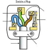
LABEL THIS:
WHAT IS EACH WIRE MADE OF AND SURROUNDED BY? WHY?
WHAT DOES A CABLE-GRIP DO?
Each wire is made of copper and surrounded by insulation. The insulation covering each wire is colour coded for easy identification.
Copper wires and plastic are both good insulators.
The extra plastic wrapping is for safety.
CABLE-GRIP holds the cable tightly in place so that wires do not become loose.
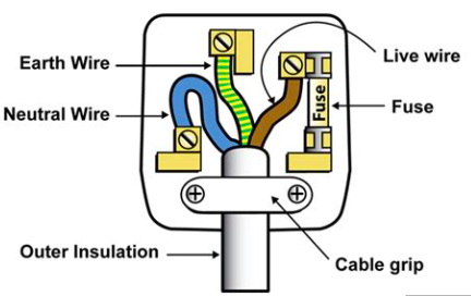
WHAT DOES THE EARTH WIRE DO?
EARTH WIRE is connected to the case of appliances. It is a safety wire to stop the exterior appliance becoming live.
WHAT IS EARTHING?
Without the earth wire, if a fault occurs and the live wire becomes loose, there is a danger that it will touch the case. The next person who uses the appliance could get electrocuted.
The earth wire is therefore connected to the case and is attached to a metal plate or water pipe underground. As the wire is made of copper, the earth wire provides a low resistance path to the ground. In the event of a fault, the live current passing through the case will follow this path to the ground instead of passing through a person.
WHAT DOES THE LIVE WIRE DO? WHAT HAPPENS IF YOU TOUCH IT?
Carries the 230 V a.c from the power supply. Current enters the device through this wire.
It is connected to a fuse for safety.
Touching the live wire can create a large p.d across the body and result in a larger current then flowing through it.
CAN A LIVE WIRE BE DANGEROUS WHEN A CIRCUIT IS CLOSED?
The live wire can be dangers even if a switch in the circuit is open (the outlet switch is off).
E.g. A TV is switched off (no current flows), but is still plugged in.
∅The live wire between the wall and the switch on the TV is still at an a.c.
∅All it need sis a path for the electricity to flow through.
∅This Plath can be provided by a damaged cable exposing the live wire.
∅If someone touches this, a p.d will be created between the live and earth, causing a current to flow and the person to be electrocuted.
WHAT DOES THE NEUTRAL WIRE DO?
Completes the circuit.
Connects to the cable in the wall.
Carries current away from the appliance.
WHICH TWO WIRES CREATE A DANGEROUS SITUATION IF THEY CONNECT?
Any connection between the live and earth wires can be dangerous because it creates a p.d, causing current to flow.
WHAT IS ONE WATT?
One watt is the power when one joule of energy is transferred in one second.
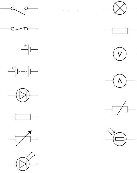
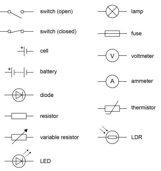
WHAT ARE THESE CIRCUIT SYMBOLS?
WHAT IS ELECTRIC CURRENT?
WHAT IS THE SIZE OF THE ELECTRIC CURRENT?
WHAT DOES THE CURRENT THROUGH A COMPONENT DEPEND ON?
WHAT HAPPENS TO CURRENT IF RESISTANCE IS GREATER?
Electric current is a flow of electrical charge. (Higher current = higher rate of flow.)
The size of the electric current is the rate of flow of electrical charge.
The current through a component depends on both the resistance of the component and the potential difference across the component.
The greater the resistance of the component the smaller the current for a given potential difference (pd) across the component.
Bigger current = more charge.
As long as the resistance is kept the same, increased voltage = increased current.
A current has the same value at any point in a single closed loop.
The direction of current flow is always from the positive to the negative terminal of the power supply.
1 Amp = 1000mA
WHAT IS CHARGE?
When current flows past a point in a circuit for a length of time.
o1C/s = 1 amp.
WHAT DOES ELECTRICAL CHARGE REQUIRE TO FLOW THROUGH A CLOSED CIRCUIT?
For electrical charge to flow through a closed circuit the circuit must include a source of potential difference.
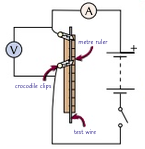
Required practical activity 15: use circuit diagrams to set up and check appropriate circuits to investigate the factors affecting the resistance of electrical circuits. This should include: • the length of a wire at constant temperature • combinations of resistors in series and parallel.
Set up equipment as shown.
Close the switch and record current and p.d.
Open the switch. Move the crocodile clip 10cm further along the wire. Allow the wire to cool.
Close the switch and record current and p.d.
Repeat steps 3 and 4 at least 5 times.
Use measurements to calculate resistance.
Plot a graph with R (y-axis) against length of wire. and draw a line of best fit. It should go through the origin - showing resistance ∝ length of wire. If it doesn’t go through the origin it could be because your first clip isn’t attached at exactly 0, so all the values are slightly off = systematic error.
WHERE ARE AMMETERS AND VOLTMETERS PLACED?
AMMETER: In circuit.
VOLTMETER: In parallel TO WHAT YOU’RE MEASURING.
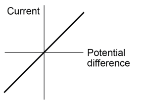
ANALYSING IV GRAPHS.
•Can be used to determine the resistance).
•A straight line through the origin = p.d and current are directly proportional (resistance is constant).
•A steep gradient = low resistance, as a large current will flow for a small p.d.
•A shallow gradient = high resistance, as a large p.d is needed to produce a small current.
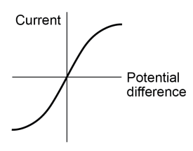
•For some resistors the value of R is not constant but changes as the current changes, this results in a non linear graph
WHAT IS AN OHMIC CONDUCTOR?
HOW ARE CURRENT AND P.D LINKED IN OHMIC CONDUCTORS?
For some resistors, the R remains constant but that in others it can change as the current changes.
Ohmic conductors e.g. wires and fixed resistors.
•A conductor that that obeys Ohm’s Law is called an Ohmic Conductor.
•The current through an ohmic conductor (at a constant temperature) ∝ to p.d across the resistor.
This means that the resistance remains constant as the current changes.
Ohmic Conductors are indicated through linear graph.
HOW DO TEMPERATURE AND R LINK?
Generally, increase in temperature —> Increase in R.
SET UP AN EXPERIMENT TO CALCULATE A COMPONENTS IV CHARACTERISTICS.
VI GRAPH OF A FILAMENT LAMP?
The resistance of components such as lamps, diodes, thermistors and LDRs is not constant; it changes with the current through the component.
The resistance of a filament lamp increases as the temperature of the filament increases.
So as current increases —> fil lamp heats up more —> resistance increases —> less current can flow —> graph gets less shallow —>curve.
•Filament lamps are non-Ohmic conductors (so the current and p.d are not directly proportional.
•The potential difference increases —> current increases. —> temperature increases (and light turns on) —> resistance will also increase.
•It is indicated by a curved graph.
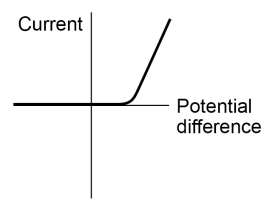
VI GRAPH OF A DIODE?
The resistance of components such as lamps, diodes, thermistors and LDRs is not constant; it changes with the current through the component.
The current through a diode flows in one direction only. The diode has a very high resistance in the reverse direction.
This is shown through a horizontal line on the x-axis, showing that no current is flowing.
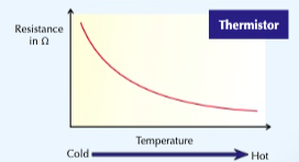
HOW DOES THE RESISTANCE OF A THERMISTOR RELATE TO TEMPERATURE?
WHAT ARE APPLICATIONS OF THERMISTORS?
The resistance of a thermistor decreases as the temperature increases.
The applications of thermistors in circuits eg a thermostat, car engine temperature sensors is required.
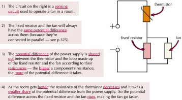
WHAT CAN SENSING CIRCUITS BE USED FOR AND HOW CAN YOU MAKE ONE WITH A THERMISTOR?
Sensing circuits can be used to turn on or increase the power to ompoinses depending on the conditions that they are in.
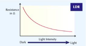
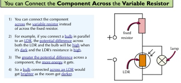
HOW DOES THE RESISTANCE OF AN LDR RELATE TO LIGHT INTENSITY?
WHAT ARE APPLICATIONS OF LDR’s?
The resistance of an LDR decreases as light intensity increases.
The application of LDRs in circuits eg automatic switching lights on when it gets dark is required.
WHAT IS A SENSING CIRCUIT EXAMPLE WHERE COMPONENTS ARE CONNECTED TO THE VARIABLE RESISTER?
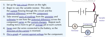
Required practical activity 16: use circuit diagrams to construct appropriate circuits to investigate the I–V characteristics of a variety of circuit elements, including a filament lamp, a diode and a resistor at constant temperature.
Build this. Make note of p.d. of battery,
Measure current. Calculate resistance.
Add another resistor in series/parallel with the first.
Measure current and p.d. and calculate resistance.
Repeat 3 and 4 until you have added 4 resistors at least.
Plot a graph.
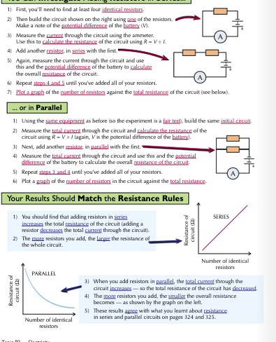
WHAT ARE THE TWO WAYS OF JOINING ELECTRICAL COMPONENTS?
There are two ways of joining electrical components, in series and in parallel.
Some circuits include both series and parallel parts.
CURRENT, P.D, AND RESISTANCE IN SERIES?
Same current through each component —> current reduces when a resistor is added —> total resistance increases.
Bigger resistance = bigger its share of the total p.d.
Total p.d of the power supply is shared between the components.
Vtotal = V1 + V2
Total resistance of two components is the sum of the resistance of each component.
This is because by adding a resistor, the two have to share the total p.d.
P.d across each resistor is lower, so the current through each resistor is also lower.
CURRENT:
IM = I1 = I2 = I3
P.D:
VM = V1 + V2
RESISTANCE:
ΩM = Ω1 + Ω2
WHAT HAPPENS IF YOU ADD MORE RESISTORS?
Adding resistors in series increases the total resistance.
• solve problems for circuits which include resistors in series using the concept of equivalent resistance.
PROS AND CONS OF SERIES?
Can design circuits to measure quantities, test components, measure p.d, resistance, current, and make sensing circuits.
If you remove or disconnect one component, the circuit is broken and they all stop.
CURRENT, P.D, AND RESISTANCE IN PARALLEL?
P.d across each component is the same —> e.g. bulbs connected in parallel will all be the same brightness.
Total current through the whole circuit is the sum of the currents through the separate components.
In parallel, there are junctions where the current either splits or rejoins.
The total current going into a junction (has to) = the total current leaving the junction.
If two identical components are connected in parallel, then the same current will flow through each component.
The total resistance of two resistors is less than the resistance of the smallest individual resistor.
Both resistors have the same p.d. —> the pushing force making current flow = same source of p.d for each resistor added.
The current has more than one direction to go in.
Increases the total amount of current that can flow around the circuit.
Increase in current —> Decrease in total resistance.
CURRENT: | IM = I1 + I2 + I3 |
P.D: | VM = V1 = V2 = V3 |
RESISTANCE: | ΩM < Ω1 + Ω2 + Ω3 |
WHAT HAPPENS IF YOU ADD MORE RESISTORS? | Adding resistors decreases the total resistance because the extra resistors will create extra pathways for charge to flow through à allows more charge to flow overall àsmaller overall resistance. |
WHAT IS THE POWER TRANSFER IN ANY CIRCUIT RELATED TO?
The power transfer in any circuit device is related to:
The potential difference across it.
The current through it.
The energy changes over time:
WHEN IS WORK DONE?
Work is done when charge flows in a circuit
WHAT IS P.D?
As charge flows around a circuit, energy is transferred to/from the charge.
The p.d between two points in a circuit = amount of energy transferred by each coulomb of charge passing between those two points. / The p.d tells you the difference in electrical potential from one point in the circuit to another.
More p.d = more charge = more current
When an electrical charge goes through a change in p.d, E is transferred.
Energy is supplied to the charge at the power source to “raise” it through a potential.
The charge gives up this E when it “falls” through any potential drop in components elsewhere in the circuit.
This means that a battery with a bigger p.d. will supply more E to the circuit for every coulomb of charge which flows round it, because the charge is raised up “higher” at the start.
WHAT IS RESISTANCE?
•The resistance of a component is the measure of how it resists the flow of charge. Each circuit component has a different resistance.
•The higher the resistance of a circuit:
oEach circuit component has a different resistance.
oThe more difficult it is for the charge to flow.
•This means that good conductors have a low resistance and insulators have a high resistance.
•Resistance is measured in Ohms (Ω).
•In a circuit, a variable resistor can be used to control the current by changing the resistance.
•For some resistors, the value of R remains constant but that in others it can change as the current changes.
HOW IS ENERGY TRANSFERRED IN CIRCUITS?
The charge carriers take energy around the circuit. (A moving charge transfers energy.)
When they go through an electrical component, energy is transferred to make the component work.
WHY DO MOVING CHARGES TRANSFER ELECTRICITY?
The charge does work against the resistance of the circuit.
WHAT DOES IT MEAN WHEN WORK IS DONE BY A FORCE?
WHAT DOES THIS DEPEND ON?
WORK IS DONE BY A FORCE:
When a force causes an object to move, work is done against frictional forces, causing the object's temperature to increase and energy is lost as heat and sound to the surroundings.
The work done by a force depends on:
The size of the force.
And the distance moved.
WHAT DOES IT MEAN WHEN WORK IS DONE WHEN A CURRENT FLOWS?
WORK IS DONE WHEN A CURRRENT FLOWS:
A current flows when there is a p.d in the circuit which is provided by a power supply. This gives each charge an amount of energy and is the work done by the power supply when a current flows.