image resolution and artefacts
1/19
There's no tags or description
Looks like no tags are added yet.
Name | Mastery | Learn | Test | Matching | Spaced | Call with Kai |
|---|
No analytics yet
Send a link to your students to track their progress
20 Terms
what principles are imaging modalities based on
variation in impedance in the tissue causes acoustic waves to be reflected back to the transducer
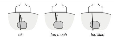
needs to be enough impedance for the beam to be reflected and not just pass through the tissue
but not too much as to stop the wave from reaching deeper structures
why is sound speed estimated in US machines and what is it a failure of?
to calculate the depths of different structures the sound speed need to be known
in the body sound speed is not constant
US machines average the sound speed → 1540m/s
close enough to give estimation of structure depths
if actual speed is too different → depth is wrong, location is wrong, artifacting → failure in condition 1
ex:
fat → slower
muscle → faster
what are the 9 ideals conditions for B mode imaging
sound speed and absorption is known and constant
born approximation stuff:
scattering is much weaker than incident wave
wave is only scattered once
array geometry:
elevation focusing restricts beam to a thin imaging plane
beamforming restricts beam to a thin line within the imaging plane
pulse:
probe can emit and detect all frequencies (infinite bandwidth)
emitted and received signals are individual pulses with an infinitesimally short pulse duration
misc:
there is no scattering from beyond the imaging depth
data is noise free
what is spatial resolution
the ability to distinguish between 2 features located close to each other
there is lateral, axial and elevation resolutions
what is lateral resolution
what affects it
what is it a failure of?
how is it improved?
→ ability to distinguish between two objects at the same depth
affected by → beam width =aperture diameter1.41λF
failure of condition 5 → beam is not a perfectly thin line
even if you move the center of the A line the sides of the beam still hits adjacent structures → lateral artefacting
improved using:
multi-zone focusing
receive beamforming
what is axial resolution?
what affects it
what is it a failure of
→ ability to distinguish between objects at different depths
affected by pulse duration → depths information is provided by their separation in time
separation>\frac{FWHM}{2}
failure in condition 6 and 7 → pulse not infinitesimally small nor does it have infinite bandwidth (not instant)
axial resolution equation
axial resolution=2coτ
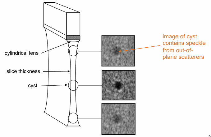
elevation resolution
what affects it
what is it a failure of
affected by the element length b → usually 20 - 30λ which is a compromise between elevation resolution and depth of field
larger length → narrower focus → better resolution
however → beam diverges quickly → poorer resolution after focus → poorer depth of field
failure of condition 4
what artefacting does elevation resolution lead to
out of plane artefacting → reflections from objects outside you slice → speckle
what does failure in condition 3 produce
waves can be scattered multiple times → multiple strong reflections between specular scatterers
b-lines
comet-tails
mirror-image artifact:
beam hit large specular surface causing beam to reflect
reflected beam hits another surface and bounces back to the specular surface
produces a mirror image across the first specular boundary
failure in condition 1
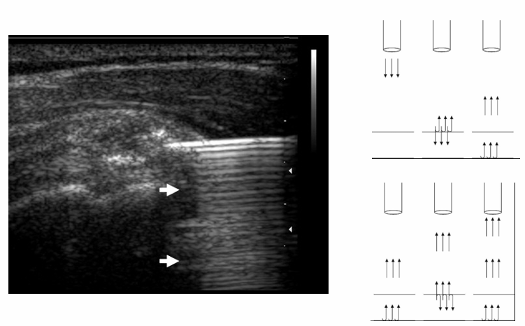
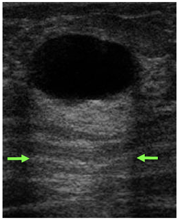
enhancement artefact:
Enhancement beyond a fluid-filled (low attenuation) region
US passes through a region of low attenuation and is absorbed less than other US waves
The time gain compensation in the area after it then enhances it above surrounding levels (it was not needed as it was less attenuated)
Time-gain-compensation is wrong as attenuation is not uniform
the reverse can occur producing shadow artefacts:
strong absorber prevents US beam from reaching area behind it
time gain compensation is insufficient leaving a dark shadowy area
refraction artefacts:
different medium densities causes sound speed to change → beam bends
causes objects to appear in the wrong place or missed
failur in condition 5, how is it minimes?
grating/side-lobe artefacts:
echoes received from the side/grating lobe are interpreted as an object originating from the main beam field of view
reduced by changing transducer design and apodisation
failure in condition 8
scattering from beyond the imaging plane → range ambiguity artefacts
scattering from beyond the image appears at shallower depth inside the image
if you change the imaging depth the artefact will move
failure in 4 and 7
→ instant pulse + thin slice = speckle (texture in US image)
medium contains many diffusive scatterer (<λ ) that are randomly distributed
may have different impedances
→ scattered wave reach the transducer and constructively + destructively interfere with each other
does not give any position or structural information as the speckle is dependent on transducer and processing
but it is deterministic (always appears the same)
how do we reduce speckling
using image compounding:
average several ultrasound images taken at different conditions → non-linear processing
this lead to images with uncorrelated speckle patterns
averaging removes this varying component
what is the drawback of compounding?
reduced frame rate
what are types of non-linear processing
persistence (temporal compounding): several subsequent image frames are averaged
spatial compounding: images taken from different scan directions are averaged
frequency compounding: images taken at different frequencies are taken
choosing transducer frequencies
transducers only have a finite bandwidth on transmit or receive (failure of 6) but this can be chosen depending on:
depth → lower frequencies can travel deeper as they are absorbed less
resolution → higher frequencies have better spatial resolution
higher frequencies = shorter wavelength → narrower focus width + shorter pulse length (better axial resolution)
what determines frame rate?
pulse repetition frequency: time required for pulse to travel to the maximum depth (Lmax) and then return to the transducer
PRF=round trip time1=2LmaxC0 remember that it is a frequency not time period
frame rate=nPRF where n is the number of scan lines
what reduces frame rate
compounding
b-mode imaging
multi-zone transmitting