B748 Flight Instruments Display System
1/32
There's no tags or description
Looks like no tags are added yet.
Name | Mastery | Learn | Test | Matching | Spaced | Call with Kai |
|---|
No analytics yet
Send a link to your students to track their progress
33 Terms
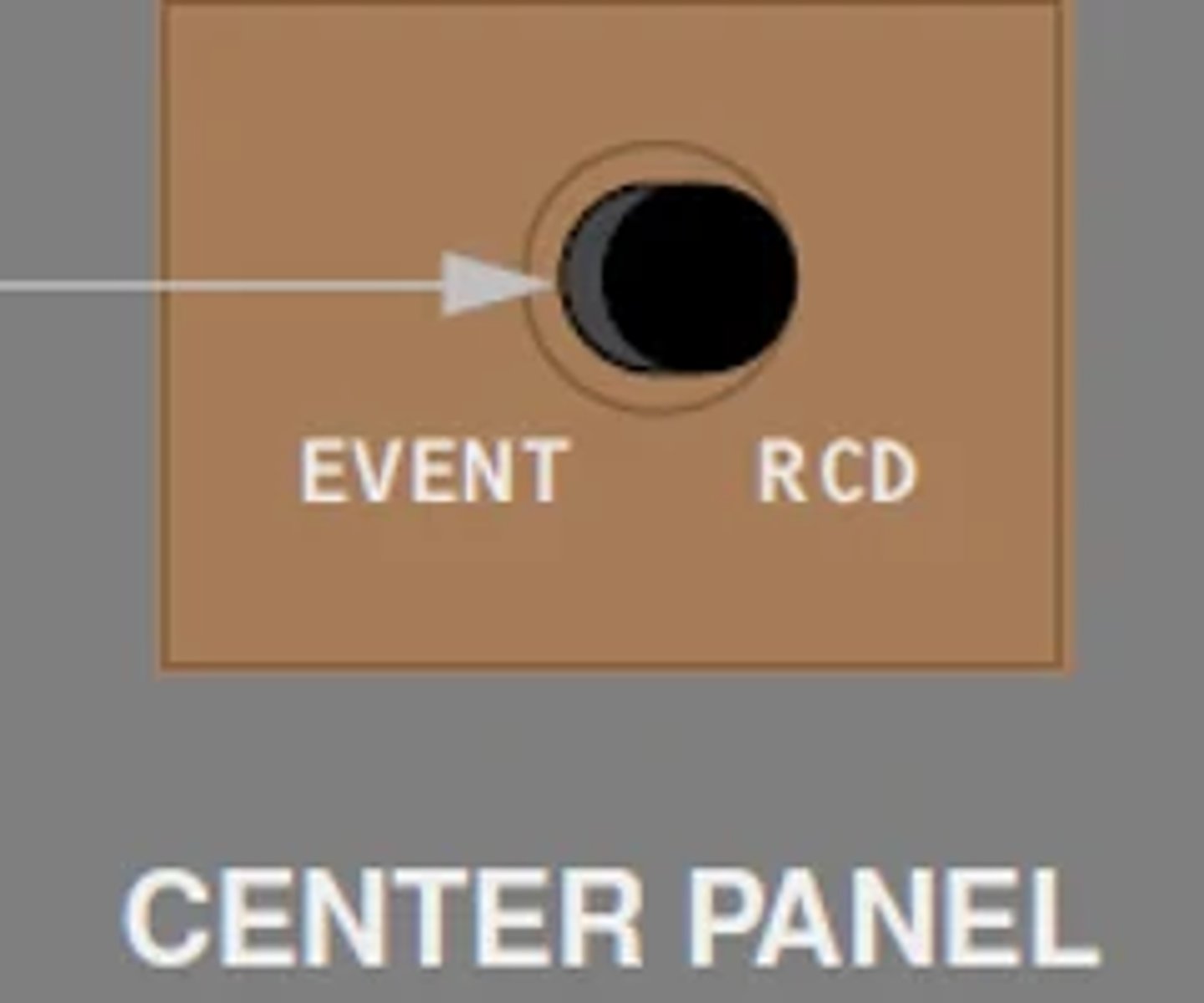
Describe the operation of the EVENT RECORD switch? FCOM 1 - 31.10.8
Records up to 5 EICAS events
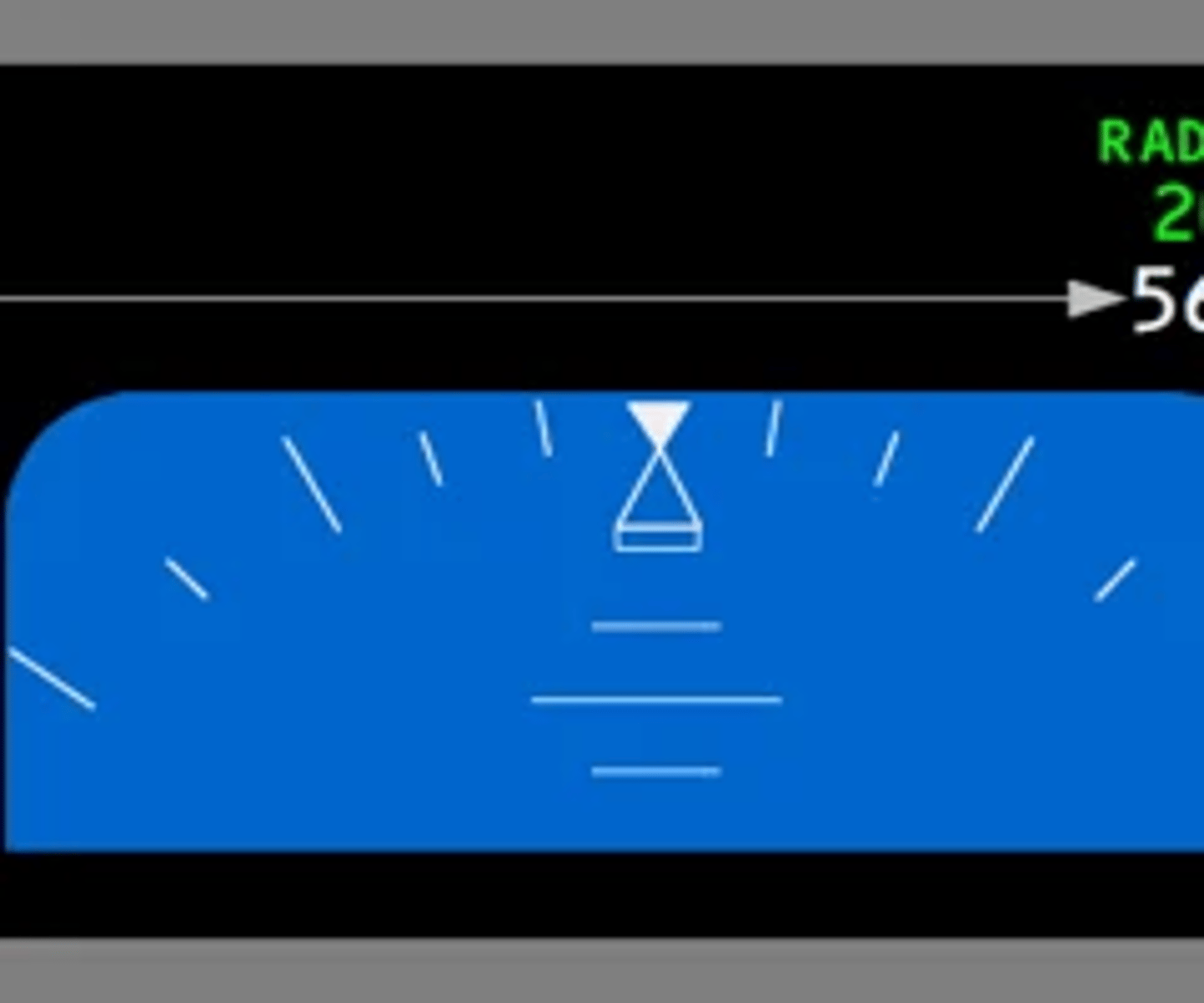
When and where is the radio altitude displayed? FCOM 1 - 31.10.18
PFD when the radio altitude is below 2,500ft
When will TCAS RA be inhibited and what is annunciated on left side of the navigation display? FCOM 1 - 31.24.4
When TA/RA is selected on the transponder panel and a GPWS or PWS warning alert occurs, TCAS inhibits RA mode and operates in TA ONLY mode. All aircraft that would have been predicted as a RA are predicted as a TA. When a subsequent GPWS or PWS warning alert occurs while a RA is occurring, the RA is discontinued and becomes a TA. When GPWS or PWS warning alerts are no longer occurring, TCAS returns to TA/RA mode and provides RAs for all appropriate TAs.

When will weather radar transceiver receive power? FCOM 1 - 31.10.62
WXR (weather radar)—
• powers radar transceiver selected on weather radar control panel
• displays in expanded MAP, MAP CTR, VSD, VOR, and APP modes
• displays weather radar information (refer to Chapter 34, Navigation Systems)
• with WXR FAIL displayed on ND, cancels WXR FAIL message

Describe EIU functions input and output? FCOM 1 - 31.20.1
The integrated display system consists of three identical EFIS/EICAS interface units (EIUs) which receive and display airplane systems information. The EIUs supply information to the flight crew on six display units:
• Captain and First Officer primary flight display (PFD)
• Captain and First Officer navigation display (ND)
• engine indication and crew alerting system (EICAS)
• the multifunction display (MFD). The lower display can be used as the
Multifunction Display (MFD), refer to Aircraft General, Chapter 20
What are the normal air data source for captain and first officer display?
Captain - L
F/O - R
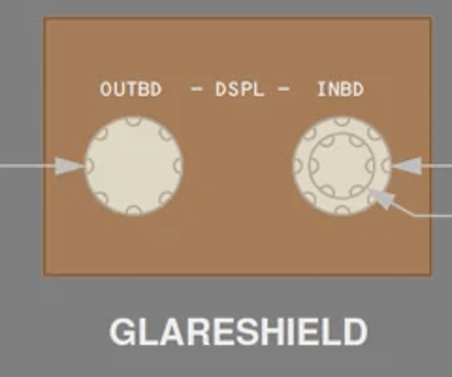
What are the features of display unit brightness control knob and what does the inner knob control? FCOM 1 - 31.10.71
1 Outboard (OUTBD) Display Brightness Control
Rotate—adjusts brightness of outboard display.
2 Inboard (INBD) Display Brightness Control (outer)
Rotate—adjusts brightness of inboard display.
3 Inboard (INBD) Display Brightness Control (inner)
Rotate—adjusts weather radar or terrain display brightness on inboard display.
What are the normal and back up power sources for the ISFD? FCOM 1 - 31.20.11
- The main battery bus powers the ISFD. Selecting the battery switch ON activates the ISFD. After 10 seconds, a 90 second initialization sequence begins.
- The ISFD is powered by a dedicated battery/charger system capable of providing power for up to 150 minutes after loss of power to the main battery bus.
Where does the approach data for the ISFD come from? FCOM 1 - 31.20.11
ILS or GLS information is provided by the left approach receiver.
What are the pitot static sources for the ISFD? FCOM 1 - 31.20.11
The ISFD receives pitot and static pressure from auxiliary pitot and alternate static sources.
What are the sources of heading information to the ISFD FCOM 1 - 31.20.11
Heading information is provided by the left ADIRU. In non-polar regions, the ISFD displays magnetic heading. In polar regions, the ISFD displays true heading with TRU displayed on the left side of the compass rose.
What is the purpose of ADM? FCOM 1 - 31.20.12
The pitot static system provides pitot pressure and static pressure to the air data modules (ADMs), integrated standby flight display, and elevator feel computer. The ADMs convert the inputs to digital data for use by the Air Data Computers (ADCs).
Describe center ADC role and switching FCOM 1 - 31.20.14
The center ADC is a standby ADC and may be selected as a replacement using the Center Air Data selector. The center ADC has its own pitot probe and ADMs but receives static pressure and AOA inputs from the same probes as the ADC it replaces and uses the opposite side TAT probe.
Where can static air temperature data be viewed FCOM 1 - 31.20.14
SAT displays on Progress page 2.
What are status messages used for? FCOM 1 - 31.21.1
EICAS status messages indicate equipment faults which affect airplane dispatch capability
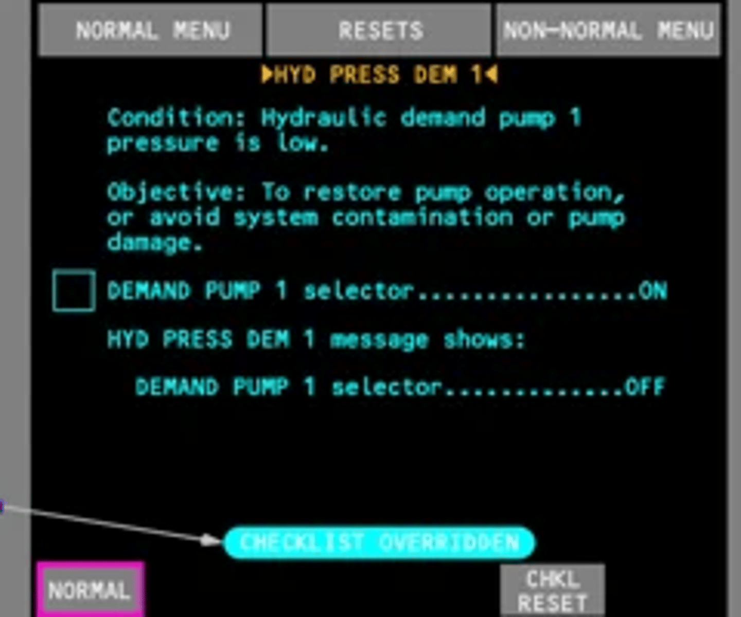
What is the implication of a rectangular symbol prefaced EICAS message? FCOM 1 - 31.21.2
A rectangular symbol [] prefaces an alert message that has procedural steps. The rectangular symbol [] also prefaces EICAS alert messages for checklists that have notes or information of which the crew must be made aware.
List the types of EICAS messages that cannot be cancelled? FCOM 1 - 31.21.2
Red EICAS alert messages remain displayed and cannot be canceled by pushing the Cancel/Recall switch.
Communication messages can not be cancelled by pushing the Cancel/Recall switch.
What differentiates Caution Messages from Advisory messages? FCOM 1 - 31.21.3
EICAS caution messages are displayed in amber below the lowest warning message. EICAS advisory messages are displayed in amber below the lowest caution message and are indented one character so they may be distinguished from EICAS caution messages.
How to view multiple pages of EICAS messages and what happens when the last page is reached? FCOM 1 - 31.21.3
Multiple pages of EICAS caution and advisory
messages can be displayed one page at a time by pushing the Cancel/Recall switch. If there are more EICAS warning messages in the list than can be displayed on one page, no page number is displayed and it is not possible to display other pages.
What are the indications when the aircraft is approaching a stall? FCOM 1 - 31.21.8
Warning of an impending stall is provided by left and right stick shakers, which independently vibrate the left and right control columns.
What triggers the EICAS message AIRSPEED LOW to display? FCOM 1 - 31.21.8
The EICAS caution message AIRSPEED LOW is displayed and the box around the current airspeed indication on the PFD is highlighted amber if airspeed is below minimum maneuvering speed.
Describe takeoff configuration warnings and inhibits FCOM 1 - 3|.2|.9
• airplane is on the ground, and
• Fuel Control switches are in RUN position, and
• engine two or three thrust is in takeoff range, and
• airspeed is less than V1, and
• any of the following configurations exist:
− flaps not in a takeoff position, or
− leading edge flap fault is detected, or
− body gear not centered, or
− parking brake set, or
− Speedbrake lever not in DN detent, or
− stabilizer trim not in takeoff range
The CONFIG message remains displayed until the airplane is configured for a normal takeoff or until engine 2 and 3 thrust is decreased below takeoff range and airspeed is less than V1.
How is altitude alert presented when approaching to the selected altitude? FCOM 1 - 31.21.10
At 900 feet prior to reaching the selected altitude a c-chord sounds and a highlighted white box is displayed around the selected altitude and the current altitude on the PFD. The highlights are no longer displayed when within 200 feet of the selected altitude.
How is altitude alert presented when deviating from the selected altitude? FCOM 1 - 31.21.10
When departing the selected altitude by 200 feet, the EICAS alert message ALTITUDE ALERT is displayed, and a highlighted amber box is displayed around the current altitude. The message and amber highlights are no longer displayed when:
• subsequently re approaching to within 200 feet of the selected altitude, or
• a new MCP altitude is selected, or
• departing more than 900 feet from the selected altitude
What are the conditions that inhibit the ALTITUDE ALERT message? FCOM 1 - 31.21.11
Alerts when departing MCP selected altitude are inhibited when:
• glideslope captured, or
• landing flaps selected and landing gear down and locked
What will show up on the ND display when data displayed exceeds the display capability? FCOM 1 - 31.23.3
EXCESS DATA
When does STATUS cue inhibit begin and end? FCOM 1 - 31.24.4
- engine start begins
- ends 30 minutes after lift off
When does the airplane takeoff inhibit apply to master caution light and beeper FCOM 1 - 31.24.8
All EICAS caution messages, except:
AUTOPILOT
AUTOTHROTTLE
DISC
NO AUTOLAND
SPEEDBRAKES
EXT
Begins:
LAND 2 or
LAND 3
displayed on
PFD, and
200 feet
radio attitude
Ends:
75 knots airspeed, or
40 seconds elapse, or
800 feet radio altitude
When does airplane takeoff inhibit apply to the fire bell? FCOM 1 - 31.24.6
V1 until 400 feet RA or 25 seconds after V1 whichever occurs first
When is EICAS warning CONFIG GEAR inhibited? FCOM 1 - 31.24.7
Lift off until 800 feet RA or 140 seconds after nose gear strut lift off, whichever occurs first.
Describe ECL override color change FCOM 1 - 31.50.14
Items displays in cyan
Describe the difference between closed loop items and open loop items and their color change FCOM 1 - 31.60.3
- close loop continuous monitor of flight deck switch, lever or selector. color change to green when completed and sensed
- open loop require flight crew to manually confirm. color changes from white to green
What is the ECL priority when on ground and in flight FCOM 1 - 31.60.7
On the ground with all fuel control switches in CUTOFF and all engine start switches not pulled, the priority is:
• checklists for EICAS warning messages
• NORMAL checklists (incomplete or not yet opened)
On the ground with any fuel control switch in RUN, or any engine start switch pulled; or in the air, the priority is:
• checklists for any EICAS alert messages that have icons
• incomplete unannunciated checklists
• NORMAL checklists