8.5 Step Response of a Series RLC Circuit
1/3
There's no tags or description
Looks like no tags are added yet.
Name | Mastery | Learn | Test | Matching | Spaced | Call with Kai |
|---|
No analytics yet
Send a link to your students to track their progress
4 Terms
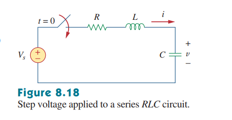
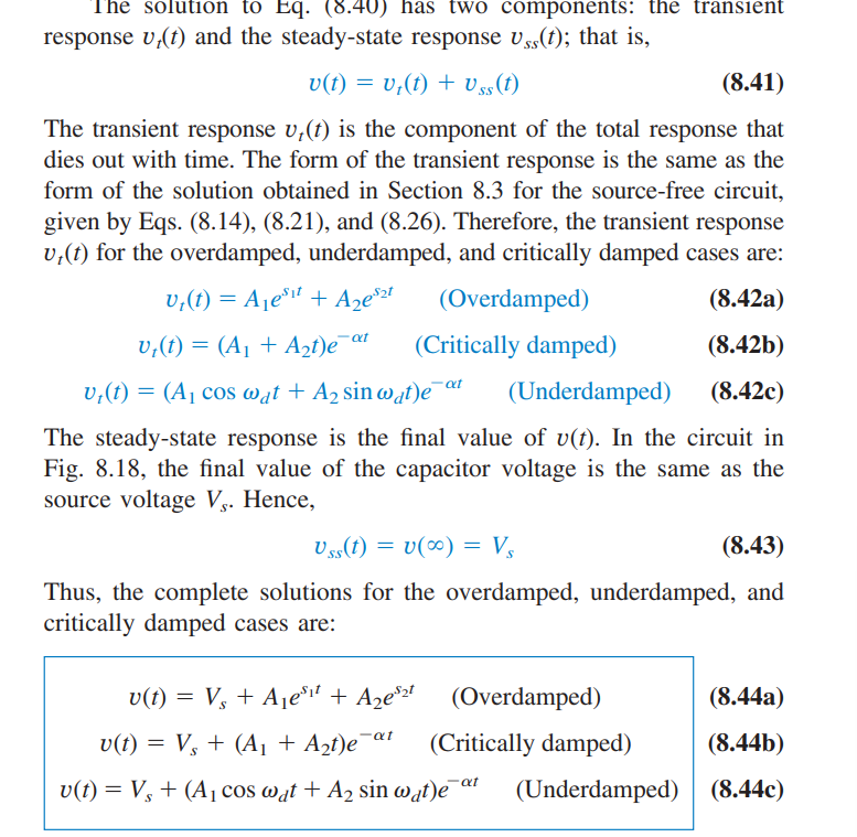
The Step Response for a Series RLC Circuit
For a series RLC circuit, the step response will typically be to a voltage source. From there, we will calculate the VOLTAGE response, NOT the current response (since, again, we are connecting to a voltage source).
Voltage Function
The voltage function is nearly identical to the previous response functions, the only difference is that the final voltage function is defined as the sum of the transient response (as if it were a source-free RLC circuit) and the initial voltage source itself.
The logic behind this is that the transient response will eventually decay to 0, so the minimum/maximum voltage of the capacitor in the series RLC circuit has to be the voltage source to which it is connected.
Auxiliary Equation/Initial Conditions
When solving for the voltage function’s coefficients, we must utilize three forms of information:
V(0)
The initial capacitor voltage at steady-state
I(0)
The initial current through the inductor at steady-state
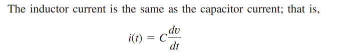
The Differential Term
This time, however, we utilize the fact that i(t) = C(dv/dt); more specifically, we utilize the fact that i(0) = C(dv(0)/dt). No longer do we use the same auxiliary equation.
filler
filler