Unit 1 Exam
1/314
There's no tags or description
Looks like no tags are added yet.
Name | Mastery | Learn | Test | Matching | Spaced | Call with Kai |
|---|
No analytics yet
Send a link to your students to track their progress
315 Terms
Refers to various techniques for producing images of internal structures (anatomy) and/or function (physiology) that are used for diagnosis
Diagnostic imaging
Entire Volume of Tissue between source and image receptor is projected onto 2D image
True
Produces x-rays
X-ray source
Receives/detects x-rays
Image receptor
Shows the radiograph/image
Image display device (for digital imaging)
Components that contribute to radiographic image formation and display
Imagine chain
Path of radiation (x-ray beam) must include ______ and _____
anatomy of interest; receptor
Consists of x-ray photons, travels in straight lines, and is divergent
features of x-ray beam
reduction in x-ray beam intensity as it travels through the anatomy
attenuation
the _____ and ____ the structure, the more x-rays are absorbed and the more the beam is attenuated
thicker; denser
Differentially attenuated by structures of different density
Incident beam
Carries information from incident beam to receptor
Transmitted beam
Black/dark structures, less radiodense, attenuating structures
Radiolucent
White/light structures, more radiodense, attenuating structures
Radiopaque
This property of an object refers to ability to attenuate or absorb xrays
Radiodensity
metal > enamel > dentin & cementum > bone > muscle > fat
MEDCBF
order of decreasing density as it appears
Range of densities on an image. Defines as difference in densities between light and dark regions
Contrast
Shows both light and dark areas with few shades of gray in-between
High contrast
Shows various light and dark shades of gray
Low Contrast
Imaging sharpness, spatial resolution, contrast resolution, magnification, distortion
What are these?
Parameters of radiographic image quality
Measures how well a boundary between two areas of differing radiodensity is revealed (ex, dark radiolucent structure and white radiopaque structure)
Sharpness
Measures how well an image reveals small objects that are close together
Spatial Resolution
Difference between object size on image and actual object size
Size distortion
Increase in size of object on image compared to actual size of object (caused by divergent paths of x-ray photons in a beam)
Magnification
Difference in appearance of object shape on image compared to actual object shape (unequal magnification of different parts of the same object)
Shape Distortion
______ should be as SMALL as possible
Focal spot, Object-receptor distance
____ should be as LONG as possible
Source-receptor distance
_____ should be parallel to the long axis of the object
Receptor
_____ should be perpendicular to the object and receptor
Central beam
An area on target of X-ray tube where x-rays are produced
Focal spot
Focal spot size for dental, panoramic, and cone beam CT machines range from ______
0.4 - 0.8 mm
A smaller focal spot yields a
sharper image
Xrays produced at different points in the focal spot that pass through the same point on an object
will NOT hit the same spot on the receptor
Blurring of object edges
geometric unsharpness, penumbra, adumbration
A larger focal spot creates a wider zone of geometric unsharpness
loss of image sharpness
Increasing _____ distance reduces x-ray beam divergence, minimizes image magnification as x-rays in the center of beam travel nearly parallel
Source-object
Increasing _____ distance reduces x-ray beam divergence, reduces geometric unsharpness as x-rays in the center of beam travel nearly parallel
source-object; source-receptor
Decreasing _____ distance reduces x-ray beam divergence, reduces geometric unsharpness and minimizes image magnification as x-rays in the center of beam travel nearly parallel
Object-receptor
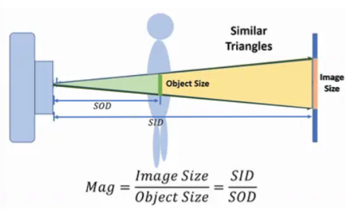
Define SID and SOD
SID = source to image distance (source-receptor distance)
SOD = source to object distance
Magnification caused by an increased object-receptor distance can be minimized by ________________
Increasing the source-object distance
Occurs when not all the parts of an object are at the same source-to-object and/or object-to-receptor distance
Image shape distortion
Minimizing shape distortion can be done by
Aligning the object and image receptor parallel with each other. Aligning the central ray perpendicular to both the object and image receptor
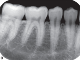
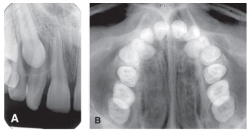
Which root appears disproportionately longer?
Palatal roots, compared to buccal roots
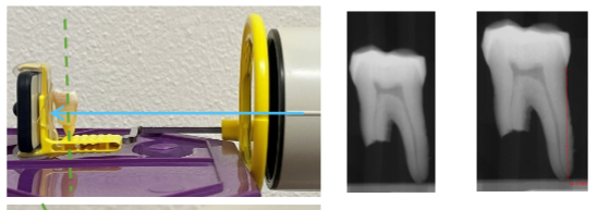
Image of object is shorter than true object.
Object is not parallel to receptor
Central ray is perpendicular to receptor, NOT object
Foreshortening
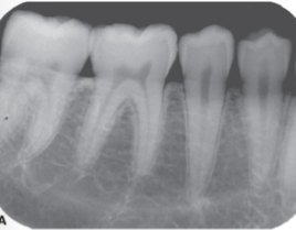
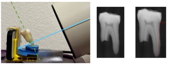
Image of object is longer than true object.
Object is not parallel to receptor
Central ray is perpendicular to object, NOT receptor
Elongation
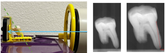
What is happening here
Foreshortening
What is happening here
Insignificant Distortion
What is happening here
Elongation
Use as small a focal spot as practical (determined by manufacturer, can’t be changed)
Increase the source-to-object distance
Minimize the object-to-receptor distance
Where are these principles important?
Maximizing Image Sharpness
If focal spot is small, what happens to image sharpness?
Increases
If focal spot is large, what happens to image sharpness?
Decreases
If source-receptor distance is short, what happens to image sharpness and image magnification
Image sharpness decreases, Image magnification Increases
If source-receptor distance is long, what happens to image sharpness and image magnification
Image sharpness increases, image Magnification Decreases
If object-receptor distance is short, what happens to image sharpness and image magnification
Image sharpness increases, Image magnification decreases
If object-receptor distance is long, what happens to image sharpness and image magnification
Image sharpness decreases, Image magnification increases
If source-object distance is short, what happens to image sharpness and image magnification?
Image sharpness decreases, Image magnification increases
If source-object distance is long, what happens to image sharpness and image magnification?
Image sharpness increases, Image magnification decreases
Circumstances that suggest a need for diagnostic imaging
Selection criteria
Examples of selection criteria
Clinical evidence of an abnormality, high probability of disease that is not clinically evident
Patient age/demographic social/medical/dental hx
Exception: BTW for detection of early interproximal caries
Should record the complete area(s) of interest
Have the least possible amount of distortion
Have optimal density and contrast to facilitate interpretation
What radiographs SHOULD do
Projections show the entire length of tooth and surrounding peri-radicular bone
PA
Projections show only the crowns of teeth and adjacent alveolar crests
BTW
Projections show an area of teeth and bone larger than periapical images
Occlusal
Consists of PAs and BWs (18-20 images) )14-16 PAs_
FMX
attached to tubehead aperture to direct x-ray beam
Position indicating device, also called a “cone” or “aiming cylinder”
Receptors have __ active side that needs to face source
1
What type of receptor uses a photostimulable phosphor plate (PSP)?
Indirect
What type of receptor uses a solid state, direct digital sensor (CCD/CMOS), corded?
Direct
This projection technique is preferred, produces images with less distortion, anatomy may prevent strict adherence
Position receptor parallel to long axis of teeth and direct central xray perpendicular to both
Paralleling Technique
Another word paralleling technique
Right-angle, long cone, or extension cone technique
In the paralleling technique, where is the receptor placed for maxillary imaging?
Toward the center/height of the palatal vault
In the paralleling technique, where is the receptor placed for mandibular imaging?
Deep in the lingual vestibule, pushing tongue out of the way toward midline
Anatomic constraints of the paralleling technique
Shallow palate/vestibule, presence of tori
Long cone is used to ____ the source-object distance
Increase
Distance from source to edge of cone ranges from ____
8-20 inches
Distortion is likely, used when anatomy is tricky
Bisecting Angle Technique
2 triangles are equal when they share 1 complete side and have 2 equal angles
Cieszynski’s rule of isometry
Receptor is positioned close to lingual surfaces of teeth, mentally bisecting angle between long axis of teeth and long axis of receptor. Xray tube positioned at right angle to bisecting line
Process of the Bisecting Angle Technique
In bisecting angle technique, actual length of tooth will be equal to that on image, except for
Multirooted teeth
What is the bone distortion of the bisecting angle technique
Alveolar ridge is projected coronal to its true position, and the alveolar bone height is distorted around teeth

Where does the cone point in + angulation
Cone points downward
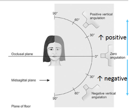
Where does the cone point in - angulation
Cone points upward
Angle between x-ray beam and line ____ to floor/occlusal plane in vertical angulation
Parallel
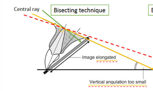
What vertical angulation error results in vertical angle being too small (under-angulation)
Elongation
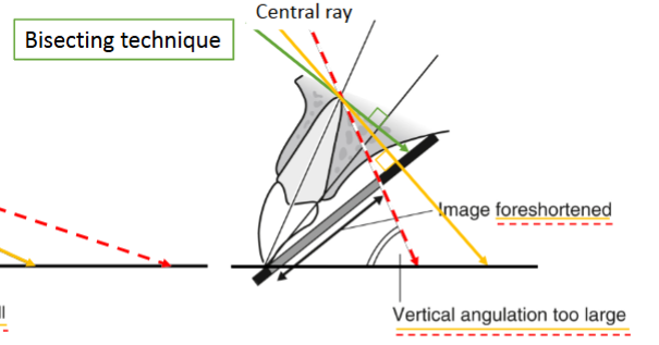
What vertical angulation error results in vertical angle being too large (over-angulation)
Foreshortening
Geometrically accurate (w/ long cone), reproducible, good periodontal bone levels, zygomatic process above upper molars
Advantages of paralleling technique
Positioning can be uncomfortable, position can be hard for operator, anatomy sometimes makes technique impossible
Disadvantages of paralleling technique
Receptor positioning is comfortable, simple and quick, adequate for most diagnostic purposes if done correctly
Advantages of bisecting technique
Foreshortening and elongation can distort image, not reproducible, perio bone levels are poorly shown, requires skill, and zygomatic process overlies upper molar roots
Disadvantages of bisecting technique
___ projection geometry produces images that are more reliably accurate for periodontal bone level evaluation than ____
BTW; PAs
Where is the vertical beam angle placed for bitewings
Parallel to occlusal plane, perpendicular to receptor, 0-10 degrees to compensate for curve of Wilson
Where is the horizontal beam angle place for bitewings
Directed through interproximal spaces, getting open contacts between teeth is ideal
When are Vertical bitewings done
When a pt has moderate-severe alveolar bone loss. Orientation increase chance alveolar crests are captured.
Primary objectives of periapical projections
Capture full length of root and 2-3mm of periapical bone, entire crowns and open contacts, and capture all interproximal bone levels
Occlusal images are used where
Pediatrics for evaluation of developing dentition
Receptor is only available in film (not digital), “tube” side is positioned toward the jaw to be examined, vertical angulation is steep, standardized projections have a desired relationship between the central ray, receptor, and region being examined
Occlusal Technique
Occlusal localizes in mesiodistal and buccolingual dimensions
Periapical localizes in mesiodistal and S-P dimensions
ID position of object relative to surrounding anatomic landmarks on both projections
Right angle technique
Uses changes in relative positions of two separate objects that occurs when the image projection angle is changed
SLOB Rule
SL in SLOB rule
“Same lingual”
lingual objects shift in same direction as tubehead
OB in SLOB rule
“Opposite Buccal”
buccal objects shift in opposite direction from tubehead