[L16] Carbon capture & storage
1/42
There's no tags or description
Looks like no tags are added yet.
Name | Mastery | Learn | Test | Matching | Spaced | Call with Kai |
|---|
No analytics yet
Send a link to your students to track their progress
43 Terms
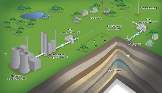
Carbon capture
CO2 can be captured from a process or the atmosphere and permanently stored geologically
Carbon separation plant
extracts CO2 from gases
CO2 capture & separation → CO2 compression unit → transport via pipeline → CO2 compression unit → CO2 injection & storage
Necessity of carbon capture & applicable sectors
fossil fuels will likely remain a major source of energy globally as is cheapest option
can be applied to electricity and industry sectors (main sources of CO2 emissions)
CSS demand
Total UK emissions in 2023 ~380 MtCO2
IEA (International Energy Agency) projects ~120 GtCO2 sequestered total by 2050 (mainly coal power)
IPCC (Intergovernmental Panel on Climate Change) up to 20 GtCO2/a of GGR in 2100 → ideal case
GGR
greenhouse gas removal
Current CSS state
~ 50 MtCO2/a operational
~ 310 MtCO2/a in various stages of development and construction
➔ <1 % of projected demand
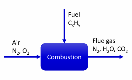
Conventional combustion
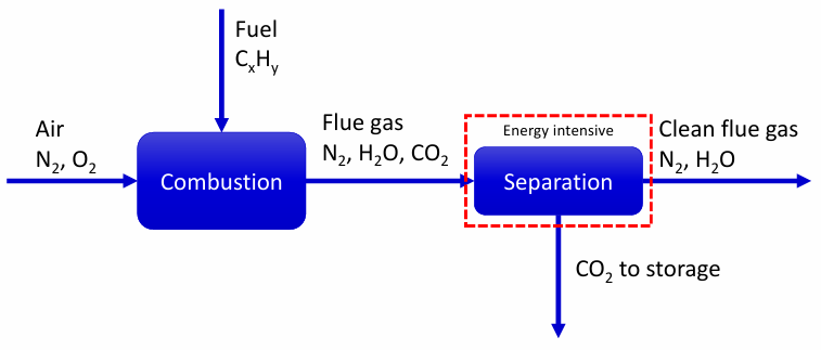
Post-combustion capture
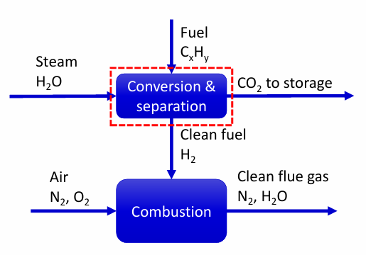
Pre-combustion capture
Oxy-fuel combustion
Separation can happen on
flue gas
fuel
air
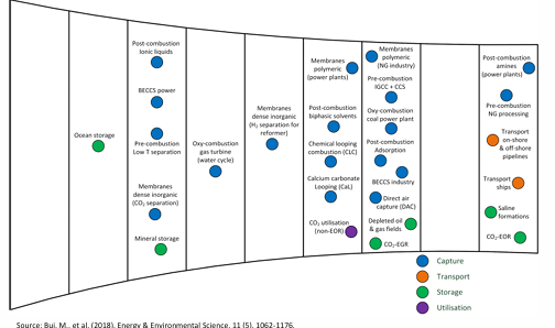
CSS current technologies
large variety
must advance through series of scale-up steps
trouble at TRL 3 (=proof of concept), TRL 6 (=pilot plant), and TRL 7 (demonstration)
technical challenges or insufficient funding
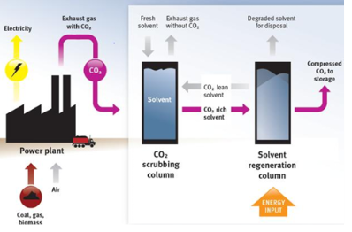
Chemical absorption post combustion capture
chemical absorption
separation using liquid solvent
Aamines such as Monoethanolamine (MEA) and Piperazine typically used as solvents
Lean solvent (blue) is contacted with the flue gas and absorbs some of the CO2
Heat is applied to the rich solvent (red) to reverse the reaction and recycle the solvent ➔ takes steam away from plant
absorption based on the fact that CO2 is slightly acidic
undertaken at low pressure (1 – 2 bara)
Chemical absorption post combustion capture advantages
“End of pipe” technology ➔ can be retrofitted to existing plant = retrofittable
Mature technology, experience with large-scale projects in the O&G industry
Flexibility → range of operating conditions
Chemical absorption post combustion capture disadvantages
High CapEx → large gas volumes
large equipment
Parasitic energy ➔ reduced plant efficiency → parasitic energy for solvent regeneration: ~20 % of steam from plant
Solvent losses & solvent disposal
→ Amine degradation
Solvent susceptible to chemical degradation in O2, SO2, CO2, high temperatures
Solvent losses to environment
Measured amine loss of ~ 0.35 – 2.0 kgsolvent/tCO2 from first pilot plants (much improved now)
Degradation products could present health risks, need to be monitored
Adsorption post-combustion capture
Adhesion of species/molecules to a solid surface
Porous solids are used in a cyclic process to separate gas mixtures → pores give more surface area per volume
Absorption depends on pressure, concentration, and temperature → cycling via pressure changes (PSA, VSA) or temperature changes (TSA)
Sorbent regeneration in adsorption post-combustion capture
Research typically focused on VSA
Fast cycle times (minutes), greater throughput
TSA not considered traditionally
Cycle times >6-12 hours
Better CO2 recovery as compared to VSA
New ‘rapid-TSA’ process developed
Cycle time ~2 minutes
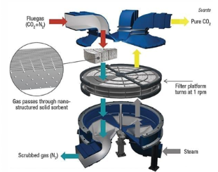
Rotary absorbers for commercial application in adsorption post-combustion capture
Rotary wheel adsorber (Svante VeloxoTherm )
Laminated gas channels
Adsorbent coated on laminations
Negligible pressure drop
Higher gas throughput
1tpd plant applied at a cement plant
30 tpd demonstrator plant in operation
500 tpd and 2,000 tpd plants designed
Advantages of adsorption post-combustion capture
Retrofittable
Range of operating conditions, many potential materials available
Particularly well suited for low concentrations ➔ direct air capture
Potentially cheaper and more environmentally friendly than amine absorption
Disadvantages of adsorption post-combustion capture
Challenging material selection
Need for cyclic processes
Energy requirements to generate vacuum
So far only used for small volumes, expensive to scale up
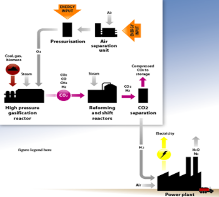
Pre-combustion capture
Hydrogen production
React hydrocarbon fuel (typically natural gas) with steam and oxygen
- Produces ‘syngas’ – CO2, CO, CH4, H2
- Syngas further reacted to produce CO2 and H2
CO2 is separated from H2 and stored
H2 is used as a clean fuel
First part of process identical to conventional H2 production process
Hydrogen / CO2 separation in pre-combustion capture
Conventional technologies from industrial hydrogen production process
Pressure swing adsorption
Cryogenic separation
➔ fundamentally based on boiling point of species
Physical absorption
Chemical absorption
Advantages of pre-combustion capture
Uses processes that are already commercially used
Lower energy penalty than post-combustion capture
Overall hydrogen production process can be very efficient (60 – 65%) – does not include efficiency of power plant
Disadvantages of pre-combustion capture
High CapEx (capital expenditure = upfront money)
Complex process – low flexibility
No commercial scale demonstration of pre-combustion capture for power generation (hydrogen turbine is issue currently)
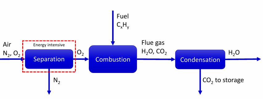
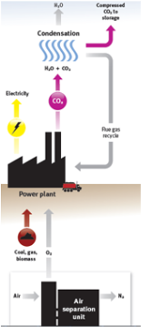
Oxy-fuel combustion
O2 separated from air
Fuel is combusted in pure oxygen
Flue gas (ideally) only contains H2O and CO2
H2O can be condensed out
No further separation of CO2 required
Air separation in oxy-fuel combustion
Cryogenic distillation
Mature, very high capacity, very high purity, high energy requirements
Vacuum swing adsorption
Mature, medium capacity, high purity, low energy requirements
Membranes
High purity, very low capacity
For a 500 MWe power plant, ≈10,000 tpdO2 (tonnes per day) is required
Only cryogenic distillation can provide this quantity
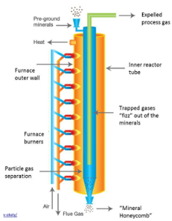
Innovation in CCS for cement
Two-thirds of CO2 come directly from the limestone
Indirect heating of calciner results in pure CO2 stream, no further separation required
Gas turbine CCS technology can be applied to flue gas from furnaces
CO2 transport technologies
Available & mature:
CO2 pipelines already exist for EOR
Ship transport already exists for food grade CO2
Large scale CCS: pipeline, ship
Small scale CCS: trucks, rail
Unlikely to be economically viable
CO2 transport challenges
Transported under pressure (≈100 bar, 30 °C) or liquefied (-37 °C, 11 bar)
Significant energy requirement for compression
Purification required before transport and storage
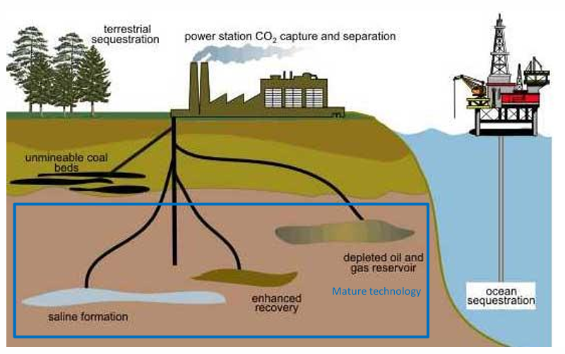
CO2 storage
enhanced oil recovery
saline aquifers
carbonation
Injection and storage of CO2 over 1 MMtpa CO2 is technically viable
>10 industrial scale demonstration projects
Enhanced Oil Recovery (CO2 injected into oil reservoir)
>98 % of properly stored CO2 will remain over 10,000 year
CO2 storage research
not concerned with actual storage of CO2
Focused on improving:
Site characterisation
Plume migration
Managing risks of leaking
Detecting leaks with certainty
Captured versus avoided CO2
additional energy required to operate the CCS plant can have associated emissions (ex: additional boiler to generate steam for regeneration)
→ CCS processes could have more emissions than CO2 they capture
Captured CO2 = gross CO2 to storage
Avoided CO2 = net CO2 (emissions of original process – emissions of new process)
Avoided CO2 always < captured CO2
➔ Cost of avoided CO2 > cost of captured CO2 (per unit of CO2)
Factors that impact cost of CCS
Location in the world
Available resources (e.g. land, water)
Technology
Brownfield vs greenfield
Technology maturity
Labour
Rates
Unionised
Commercial
Risks
Contingencies
Warranties and insurances
Price of CO2
Capture process
Technology choices
Chemicals and fuel cost
Transport
Mode of transport
Route distance
Flow rate through pipeline
Pressures
Storage
“Finding costs” / exploration
Capacity
Injectivity
Containment
Evolution of cost number of plants in operation
learning curve
costs will reduce as more plants are built
Costs versus CO2 concentration
lower concentration = more expensive = more difficult to separate a dilute stream
not suitable for small scales (house boilers for ex)
GGR technologies
greenhouse gas removal necessary for 1.5C target
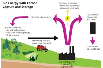
Bioenergy with carbon capture & storage (BECCS)
Direct air capture (DACCS)
Bioenergy with CSS
Feasible technology
Social aspects & social acceptance
Life cycle analysis needed to calculate net carbon removals
Drax bioenergy plant to be fitted with post-combustion CCS
controversial ➔ burning trees and biomass then capturing CO2
must replant for it to be effective
energy created by burning biomass ➔ CO2 emitted and trapped
= two steps of removal (biological + geological)
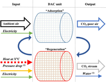
Direct air capture
Adsorption based (Climeworks & others) (solid materials)
Absorption based (Carbon Engineering) (liquid chemicals)
Technically feasible, but needs large energy input as CO2 is very dilute
Economically questionable
Socially acceptable
No large-scale demonstrations yet
DACCS vs BECCS
DACCS
Lower land requirement
Higher social acceptance
Energy consumer
Very expensive
BECCS
Higher land requirement
Lower social acceptance
Energy producer
Cheaper (but still expensive)
Both have their place:
Region specific requirements
Life cycle assessment to calculate net removals ➔ make sure CO2 removed >> CO2 caused by operating plant
CO2 utilisation
Convert the captured CO2 to valuable products
Enhanced oil recovery
Chemicals
Plastics
Food/beverage
Main sectors using CO2 as feedstock:
fertilizer (urea)
methanol (fuel) → can use carbon to make it → recycling carbon
inorganic carbonates (cement-like materials, minerals)
organic carbonates / polyurethanes
technological use (supercritical CO2, solvents, extraction)
food & drink (carbonated drinks, modified atmosphere packaging, dry ice)
CCS barriers
Every element required for CCS is already proven but is not deployed
Economics
No inherent value: not doing CCS will always be cheaper
Product (CO2) has no value
Transport & storage infrastructure not available / too expensive
Policy
Regulations, difficult permitting processes
No mandates for CCS
Carbon prices not high enough
Making it a commercial reality
Any current CCS examples involves some amount of public funding → reduces capital costs for developer
Incentives for carbon capture (e.g., US: 85$/tCO2 stored)
Carbon pricing to make unabated fossil fuels less attractive
Mandates (e.g., emission standards)
Manage risks associated with CCS projects
Pick the right application
Service providers and users
Power companies do not want to start operating CO2 stores
Clear transfer of liability needed
CCS criticism
Plenty of points of criticism
Unreliable / technically infeasible
Increases emissions
Prolongs use of fossil fuels
Distraction / Diverts investment from other “clean” solutions
Waste of taxpayer money
Greenwashing
Not zero emissions ➔ Some are justified, others not
CCS conclusion
Required to achieve climate targets, but should not compete with other low carbon technologies (e.g., renewables)
Provide different services & value in the economy
CCS technologies are well understood and considered mature
Improvements are possible, but current technology is sufficient to deploy CCS
Need to consider the whole energy system
can provide value with power system resilience (grid balancing)
combination of technologies are required to achieve emissions targets
can provide emission reductions for industry
some processes do not have CO2-free alternatives at all, or that will be available at large scale by 2050
CCS required in the short-term (~30 years) while transitioning to renewables and new industrial processes
GGR is no longer optional
Key challenge is to find a ‘business case’
Specific for each scenario
Supportive policy framework and clear financial models needed
Transparency essential for public acceptance, need to show successes