Electricity
1/32
There's no tags or description
Looks like no tags are added yet.
Name | Mastery | Learn | Test | Matching | Spaced | Call with Kai |
|---|
No analytics yet
Send a link to your students to track their progress
33 Terms
current
the rate of the flow of charge
conventional current vs actual current
conventional current: positive to negative
actual current: negative to positive
resistance and temperature
temperature increases - amplitude of vibrations increases - more frequent collision of electrons with metal ions - resistance increases
current increases - more conduction electrons collide with the metal lattice ions - transfer of the electron kinetic energy to the positive ions - component / wire heats up due to increase in amplitude of vibrations of positive metal ions / increase in rate of vibration - greater number of collisions per second - increased resistance
the resistance of a filament lamp will be lowest when it is first switched on, hence the initial current will be at its largest value, causing a sudden rapid change in temperature - this is why it is more likely to fail when it is first switched on.
potential difference
the work done per unit charge between two points when charges when charge moves between them
insulator, conductor and semiconductor
insulator - electrons are not free to move - don’t flow when a potential difference is applied
metals - conductor - some delocalised electrons - will flow when a potential difference is applied
semiconductor - number of charge carriers increases with temperature or light intensity as electrons are liberated - reducing resistance
number of electrons
(current x time) / e = number of electrons
potential difference in series vs in parallel
series: Vs = V1 + V2 + …
parallel: Vs = V1 = V2 =…
electromotive force: emf
the amount of chemical energy transferred to electrical energy per unit charge through power source / work done in moving 1C of charge whole way around circuit
similar to voltage but takes into account internal resistance of the power supply, making it greater than the voltage
emf=IR+Ir
R is circuit resistance and r is internal resistance
Internal resistance
the resistance inside a source of electrical energy
courses a loss of pd per unit charge when current passes through it
Terminal potential difference
the pd across the terminals of a power supply
power
work done per unit time
power = current x potential difference
resistance and ohms law
a measure of how difficult it is for current to flow through a component in a circuit - ratio of voltage across component to current through component
R = V/I
the pd across a metallic conductor is proportional to the current it, provided the physical physical conditions. (temperature) do not change
measuring resistance
set up a series circuit
ammeter placed in series used to measure current flowing through it
ammeter should have zero resistance to avoid altering the reading due to internal resistance
voltmeter placed in parallel and used to measure pd across it
voltmeter should have infinite resistance to stop current flowing though it
each time variable resistor is adjusted, a reading is taken from the ammeter and the voltmeter
voltage current graph plotted - gradient is the resistance of the resistor for an ohmic component only
for non ohmic components, instantaneous resistance must be found using instantaneous values of current and pd.
factors affecting resistance
resistance is directly proportional to length
inversely proportional to cross sectional area
the constant of proportionality is the resistivity
current takes the path of least resistance
resistivity
the resistance per unit length x the cross sectional area of a material
superconductors and the critical temperature
wire or device made of a material that has 0 resistivity at and below a critical temperature
electrical resistivity drops to 0 as soon as cooled to critical temperature - superconducting
when a current flows through it, no resistance so no pd - current has no heating effect
applications of superconductors
superconducting power cables - high temperature superconductors - lossless transmission of electrical power - no electrical energy dissipated in overcoming resistance
superconducting electromagnet - uses coils of superconducting wire - cooled to low temperatures during operation. can produce stronger magnetic fields than ordinary iron core electromagnets and can be cheaper to operate - used in mri scanners
ohmic and non ohmic components
ohmic components have a constant value of resistance as the current through it varies- current directly proportional to potential difference provided physical conditions do not change
non ohmic component have resistance varying with current
positive and negative temperature coefficient
ptc - resistance increases with increasing temperature
ntc - resistance decreases with increasing temperature
filament lamp
When switched on, temp is low - resistance is low
current increases rapidly and becomes very high
temperature of filament also increases rapidly and becomes very high
maximum heating at start as current peaks - energy supplied more rapidly than lost - filament could melt and fail
resistance also increases with temperature
increase in resistance decreases current
curren steady when constant temperature - energy supplied = energy dissipated from filament
Measuring resistivity of wire
measure diameter at 3 different points along wire and take an average
calculate cross sectional area
switch on and take readings of current from ammeter and potential difference from voltmeter
change length of wire and measure new I and V
measure length of wire
vary resistance on variable resistor to take multiple I V readings for each length of wire ( and find a average)
calculate R using V/I for each length
plot R against L (graph is straight line)
R = rho*L / A
gradient = rho/A
A x gradient to find resistivity
maximum power delivered to load
when load resistance = internal resistance of the source
conservation of energy and charge in a circuit
1C of the charge gains Ɛ J on passing through cell
1C transfers Ir J in cell
then transfers energy to components IR J
measurement of internal resistance
circuit with cell, ammeter, variable resistor in circuit
voltmeter in parallel across cell
take readings of the pd and current using ammeter and voltmeter while resistance is varied
as current increases, terminal pd decreases because energy transferred by internal resistance Ir increases
emf is displayed on a voltmeter as terminal pd only when no current flows
rearrange emf equation V=−Ir+Ɛ
circuit with cells in series
if in same direction, emfs add
if in different directions, find difference
identical cells in parallel
each time an electron passes through the power supply, it can only pass through one of the cells, therefore all the cells combined act as a single source of emf
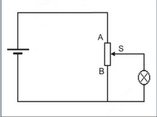
potential divider
two or more resistors in series connected to a source of pd
the ratio of the potential differences across each resistor is equal to the resistance ratio of the two resistors

potential divider with variable pd
when sliding contact at B, resistance of branch parallel to bub has no resistance - resistance of branch with bulb has greater resistance -all current arriving from positive terminal to the junction will flow through first loop - no current through bulb. Also no potential difference across bulb as it is connected in parallel to a wire with no potential drop across it - does not turn on
as sliding contact moves towards A, the resistance of branch connected in parallel to bulb increases - not as small compared to resistance in branch with bulb - proportion of current through bulb increases (current through branch with resistor decreases) - the pd across bulb also increases as the potential drop it is connected in parallel to becomes greater - gets brighter as power transferred electrically to bulb increases
At A, the supply pd is across branch connected in parallel to bulb and so across the bulb - bulb also receives maximum possible current
Kirchhoff’s 1st Law:
at any junction in a circuit, the total current entering the junction is equal to the total current leaving the junction.
Kirchhoff’s 2nd Law:
for any closed loop in a circuit, the sum of the emf’s round the loop is equal to the sum of the potential drops around the loop.
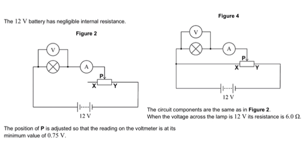
potentiometer circuit vs variable resistor circuit
Fig 4 (potentiometer) voltage range 0 -12V
Fig 2 voltage range 0.75 - 12V
Potentiometer has wider voltage range
At any particular voltage across lamp, more power dissipated in potentiometer circuit (12V across variable resistor always)
whereas for Fig 2, variable resistor only receives a portion of 12V across it
for any current in lamp, there is always more current in figure 4 circuit, producing more heating
purpose of a fixed resistor in a variable resistor circuit
to limit the current, preventing a short circuit and overheating of battery
to divide the terminal potential between two resistors
operating current
required to turn on / normal brightness