Review of Chapter 6-13 -- *Visualization, Modeling, and Graphics for Engineering Design* by Lieu & Sorby
1/91
There's no tags or description
Looks like no tags are added yet.
Name | Mastery | Learn | Test | Matching | Spaced | Call with Kai |
|---|
No analytics yet
Send a link to your students to track their progress
92 Terms
Assembly Constraints
Relationships (e.g., Concentric, Coincident, Distance) defined between parts in an assembly to position them correctly and define their degrees of freedom.
Associativity
The property where a change made to a part model automatically updates that part in all assemblies where it is used.
Base Instance
The first, fixed component in an assembly. All other parts are positioned relative to it.
Bill of Materials (BOM)
A tabular list of the components, with quantities of each for the parts, that make up an assembly.
Bottom-Up Modeling
The process of creating individual parts first and then bringing them together into an assembly.
Clearances
The minimum distances between two instances in an assembly.
Components
References of object geometry (part files) used in assembly models.
Exploded Configuration
A view of an assembly that shows instances separated from one another, used as the basis for an assembly drawing.
Hierarchy
The parent-child relationships between instances in an assembly.
Instances
Copies of components that are included within an assembly model.
Interference
The amount of overlap between two instances in an assembly.
Subassembly
A logical grouping of assembly instances that is treated as a single entity within the overall assembly model.
Top-Down Modeling
The process of establishing the assembly and its hierarchy before the individual components are created.
Adjacent Views
Orthogonal views presented on a single plane that are created immediately next to each other.

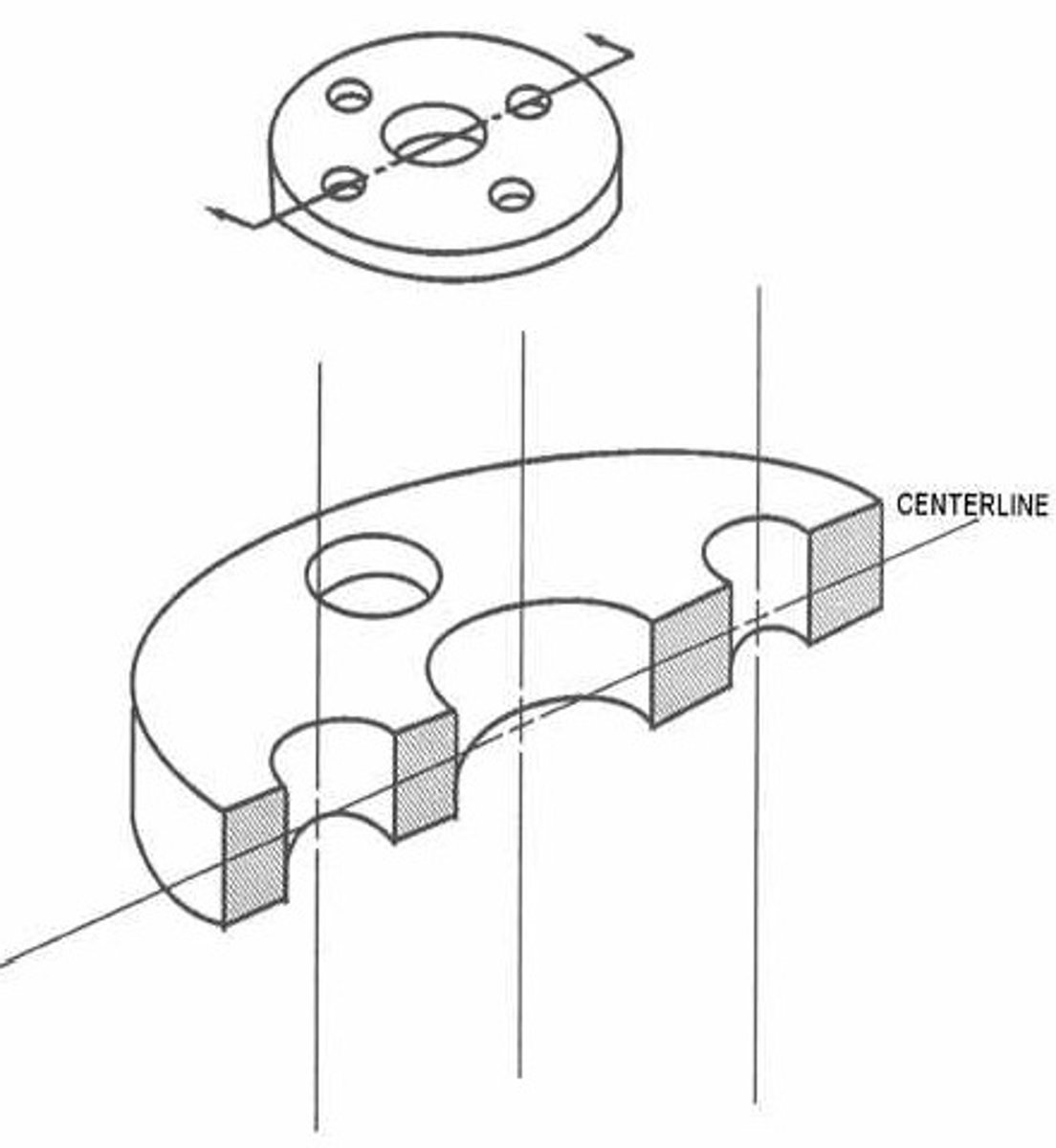
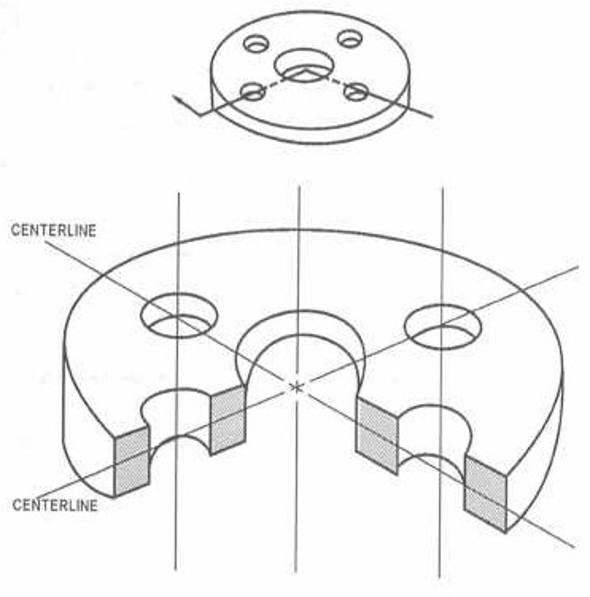
Centerline
A series of alternating long and short dashed lines used to identify an axis of rotational symmetry.
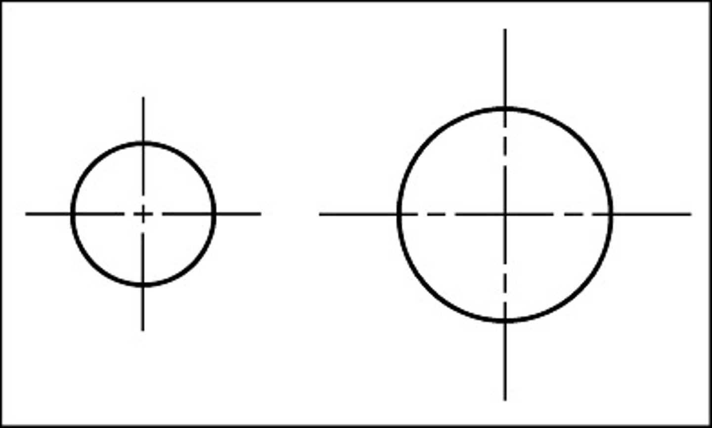
Centermark
A small right-angle cross that is used to identify the center of a circle or arc, representing the end view of an axis.
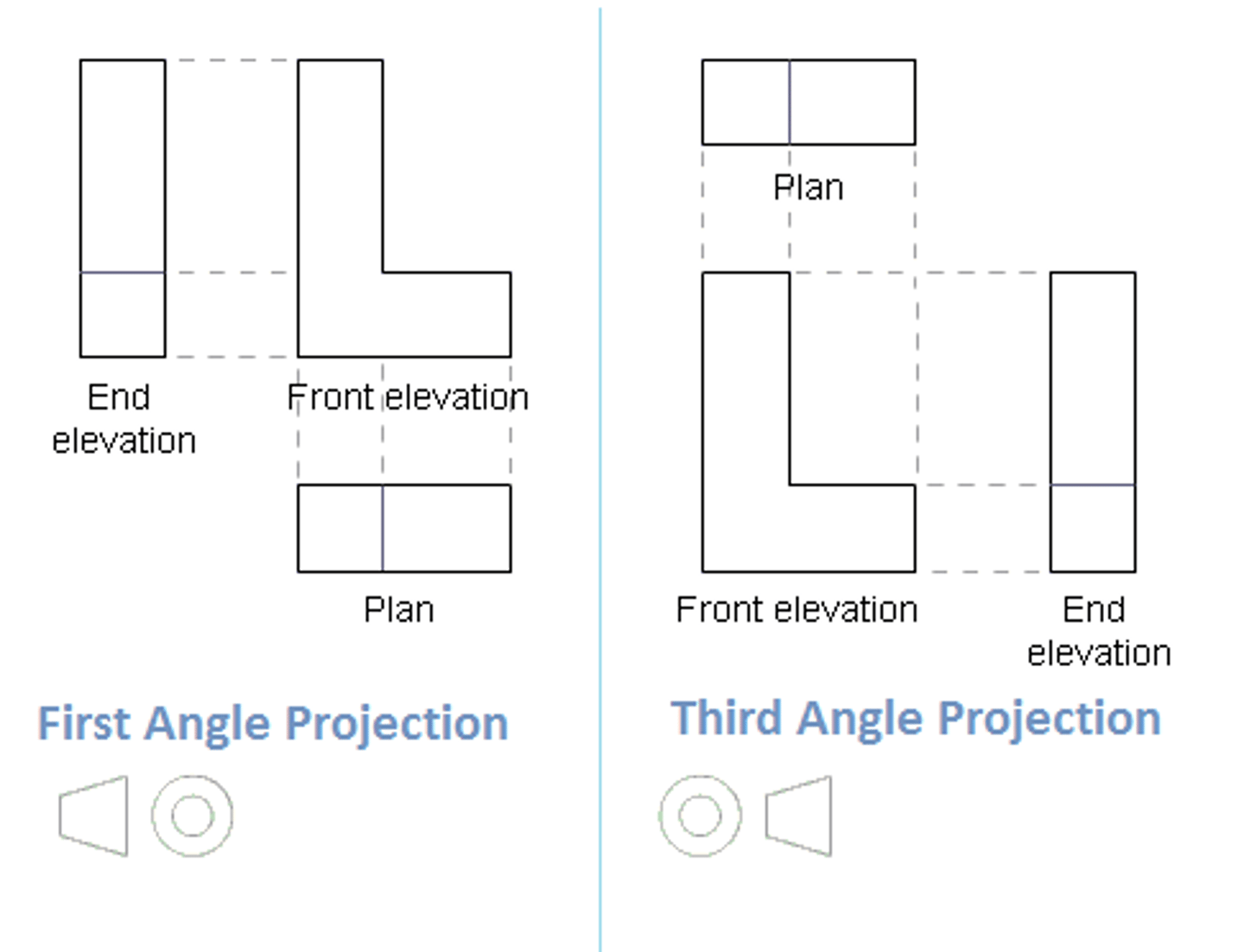
First-Angle Projection
A projection standard where the object is placed between the viewer and the projection plane. .
Basically: From the front profile, the right and top views are positioned to the LEFT and BOTTOM

Glass Box
A visualization aid where an object is imagined inside a transparent box, and its six principal views are projected onto the sides, which are then unfolded into a single plane.
Hidden Lines
The representation, using dashed lines, of edges that cannot be seen from the current viewing direction because the object is opaque.
Multiple Views
The presentation of an object using more than one image on the same drawing.
Multiview
Refers to a drawing that contains more than one image of an object, where adjacent images are orthogonal projections.
Orthogonal Projection
The process of creating a view of an object using projection lines that are perpendicular to the viewing plane.
Preferred Configuration
The standard drawing presentation of an object using its top, front, and right-side views.
Six Standard Views (Principal Views)
The top, front, bottom, rear, left-side, and right-side views of an object.
Third-Angle Projection
A projection standard where the projection plane is between the viewer and the object. (Common in the US).
Basically: From the front profile, the right and top views are positioned to the RIGHT and TOP
Viewing Plane
A hypothetical plane between an object and its viewer onto which the image of the object is imprinted.
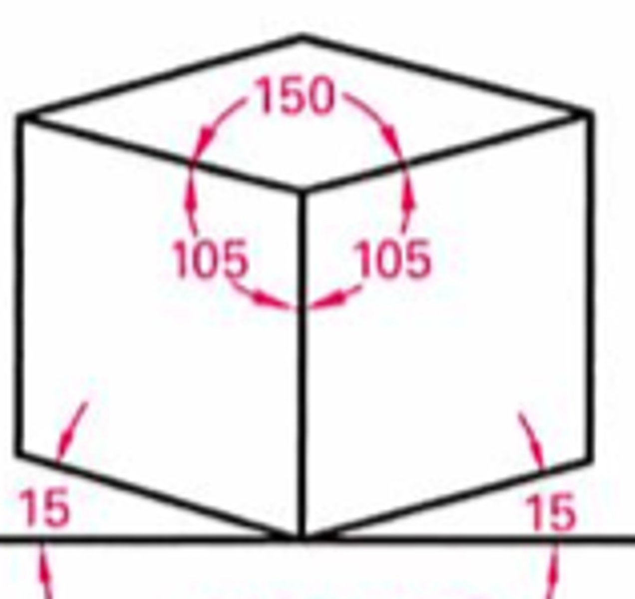
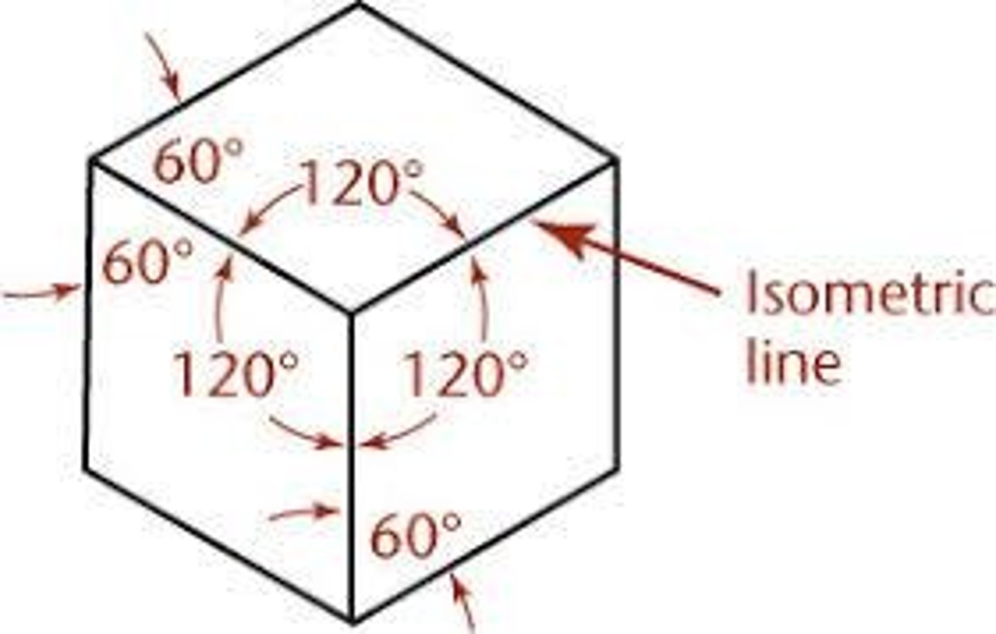
Axonometric Drawing
A pictorial drawing where the object is rotated so all three axes are visible, with a constant scale factor in each direction.
Basically: the three different views-- Isometric (the angles of all axis are equal), Dimetric (the angles of only 2 axis are equal), Trimetric (none of the axis angles are equal).
Cabinet Oblique Drawing
An oblique drawing where the receding axis is drawn at half-scale to reduce VISUAL DISTORTION.
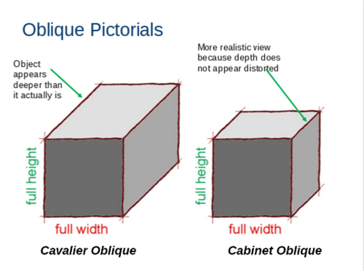
Cavalier Oblique Drawing
An oblique drawing where the receding axis is drawn at full/true-scale.
Visually it creates a stretched illusion as you can see from the attached image... thats why its important to make this distinction.

Dimetric Drawing
An axonometric drawing where the scale factor is the same for two of the three axes.
Elevation View
In perspective drawing construction, the front view of the object (literally, the front view).
Ground Line (GL)
In perspective drawing, a line on the elevation view that represents the height of the ground.
Basically: the flat line on the drawing the represents the ground
Horizon Line (HL)
In perspective drawing, the line that represents the horizon, where left and right vanishing points are located.
Isometric Drawing
An axonometric drawing where the scale factor is the same for all three axes (120 degrees between axes).
Isometric Lines
Lines on an isometric drawing that are parallel to one of the three main isometric axes.
Measuring Line (ML)
A vertical line used in perspective drawing to transfer heights from the elevation view.
Measuring Wall
A line that extends from the object to a vanishing point to help establish horizontal locations in a perspective drawing.
Oblique Pictorial
A sketch of an object that shows one face in the plane of the paper and the third dimension receding at an angle.
Perspective Drawing
A pictorial drawing where parallel lines converge at vanishing points, offering the most realistic presentation.
Pictorial
A drawing that shows the 3-D aspects and features of an object.
Picture Plane (PP)
In perspective drawing, the viewing plane through which the object is seen.
This is a bit different than the viewing plane. Think of the viewing plane as where the drawing is IMPRINTED on for you to see... think of the picture plane as a window through which you see the drawing.
Plan View
In perspective drawing construction, the top view of the object. (Birds eye view pretty much)
Station Point (SP)
In perspective drawing, the theoretical location of the observer's eye.
Trimetric Drawing
An axonometric drawing where the scale factor is different for all three axes.
Vanishing Point (VP)
The point on the horizon line where parallel lines appear to converge.
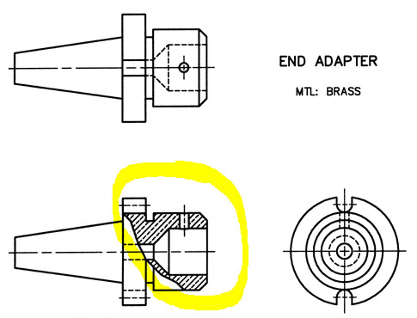
Broken-Out Section
A section view where an irregular portion of the object is broken away to reveal interior detail, without a full cutting plane line.
Cutting Plane
A theoretical plane used to hypothetically cut and remove a portion of an object.
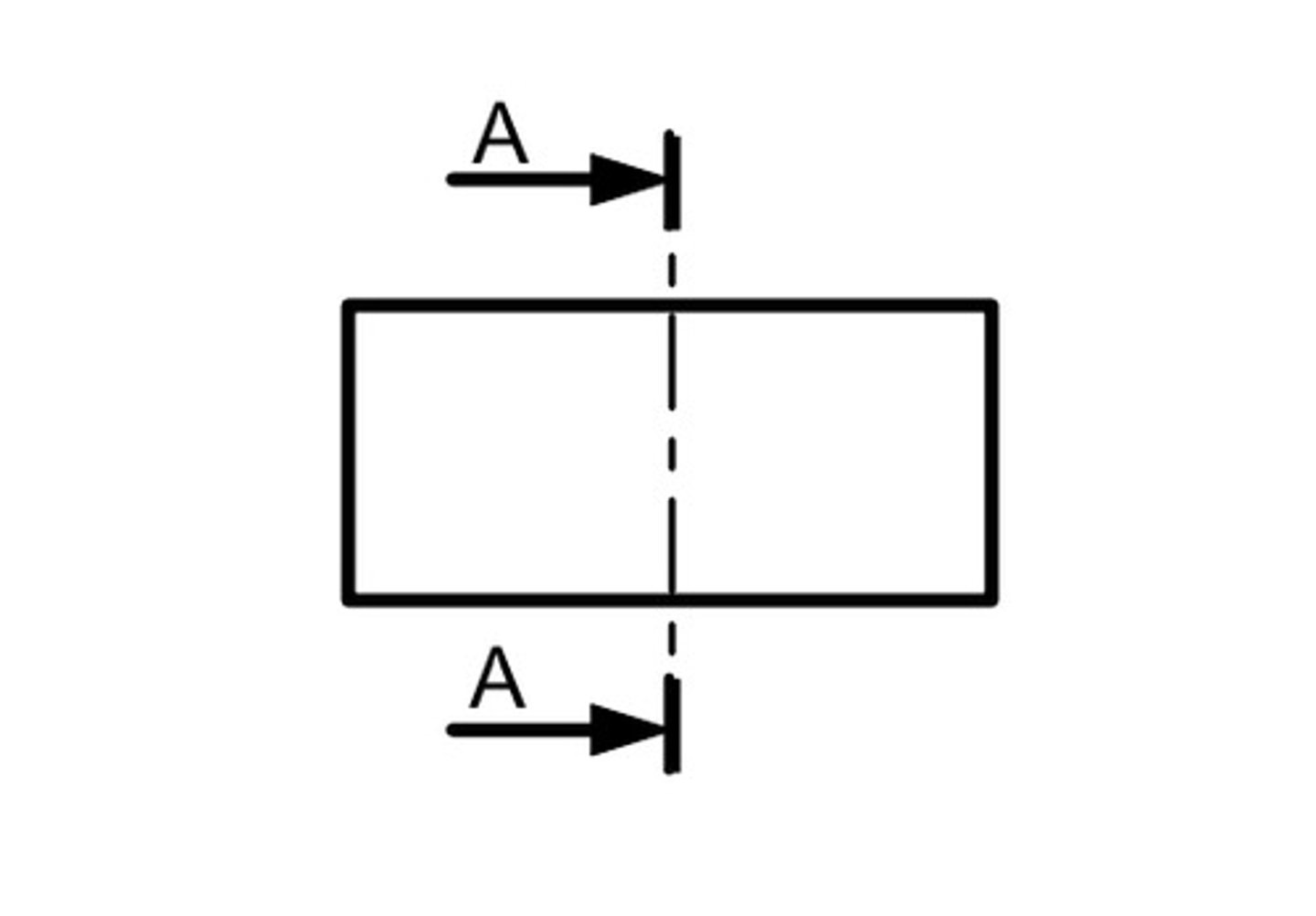
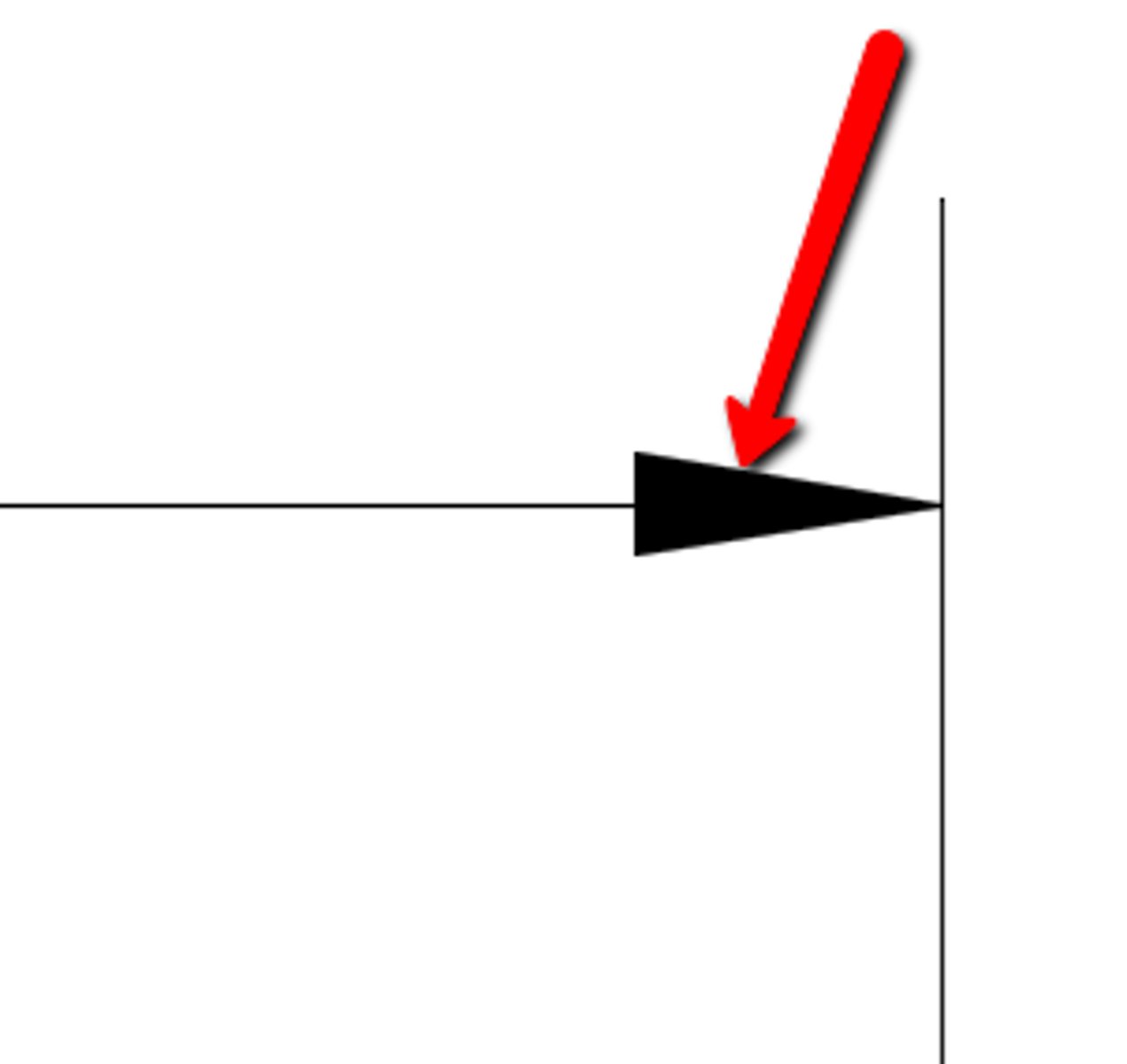
Cutting Plane Line
The line on an orthographic view that shows the path of the cutting plane, with arrows indicating the viewing direction.
Full Section
A section view produced when a single cutting plane cuts the object completely into two pieces.
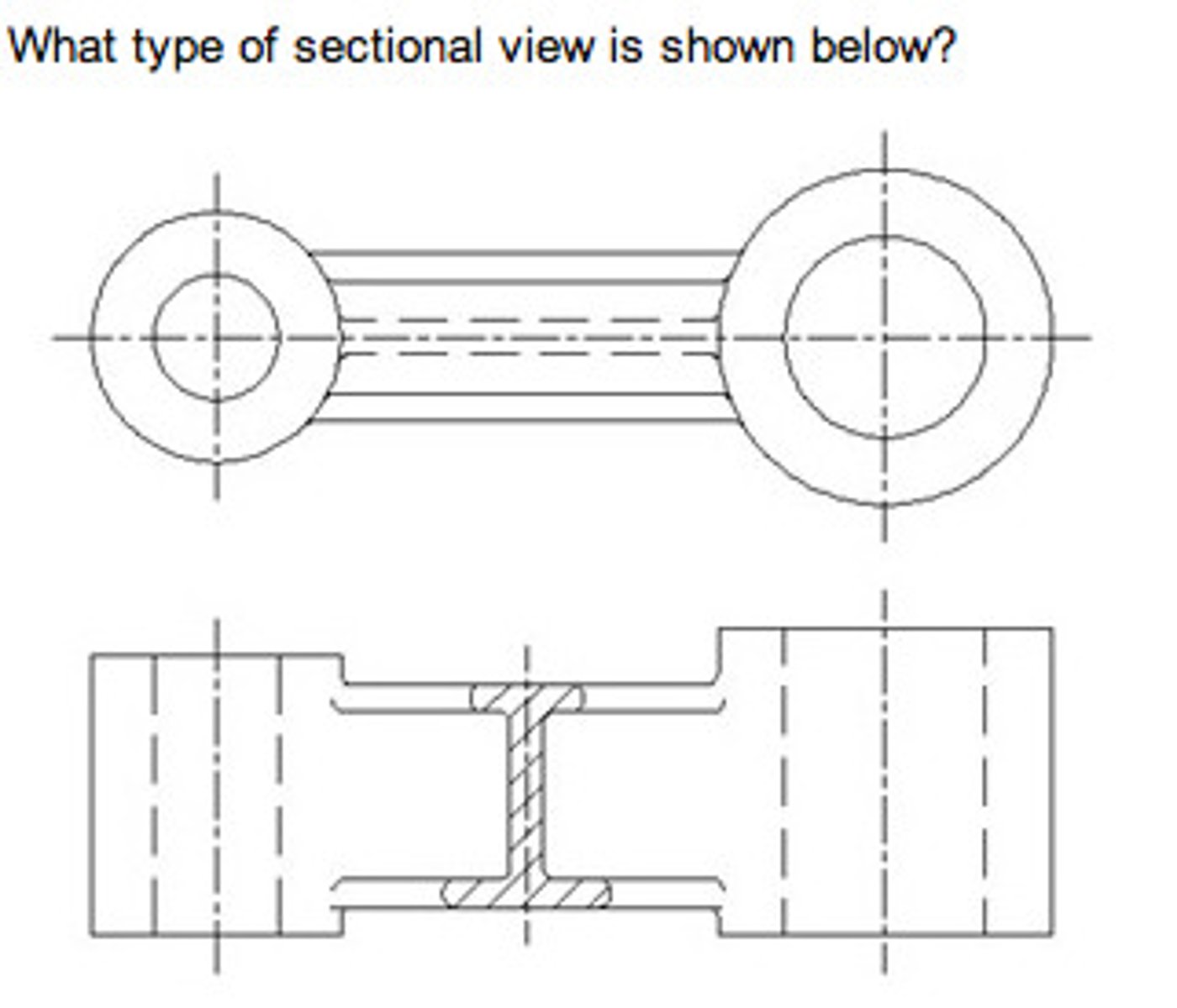
Half Section
A section view produced when a cutting plane cuts an object only up to a plane or axis of symmetry.
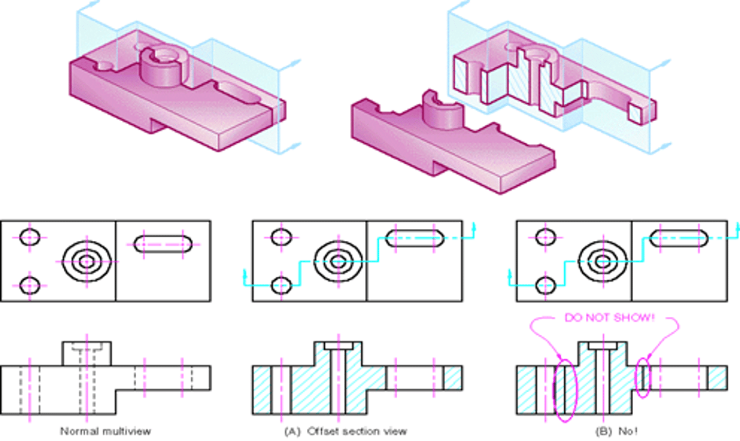
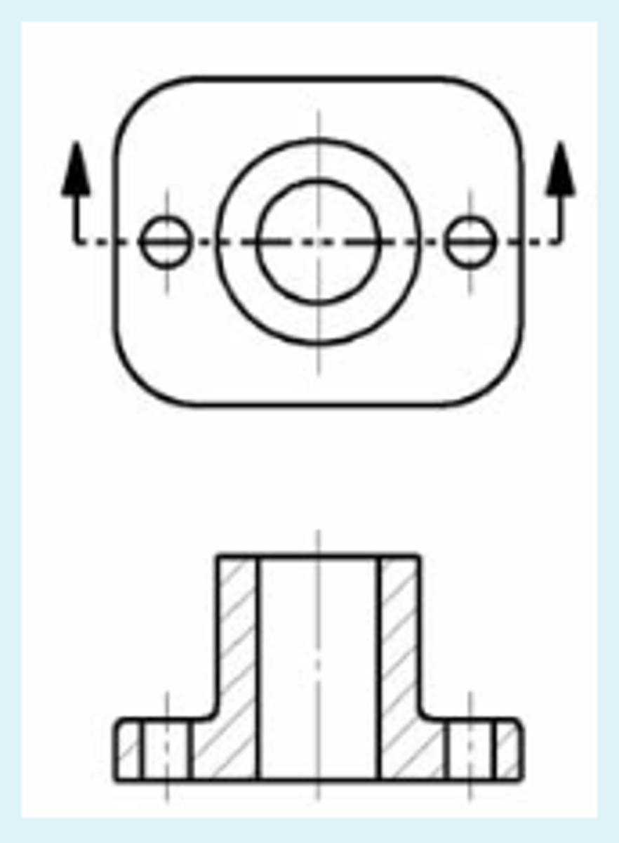
Offset Section
A section view produced by a stepped cutting plane that passes through multiple, offset features of interest.
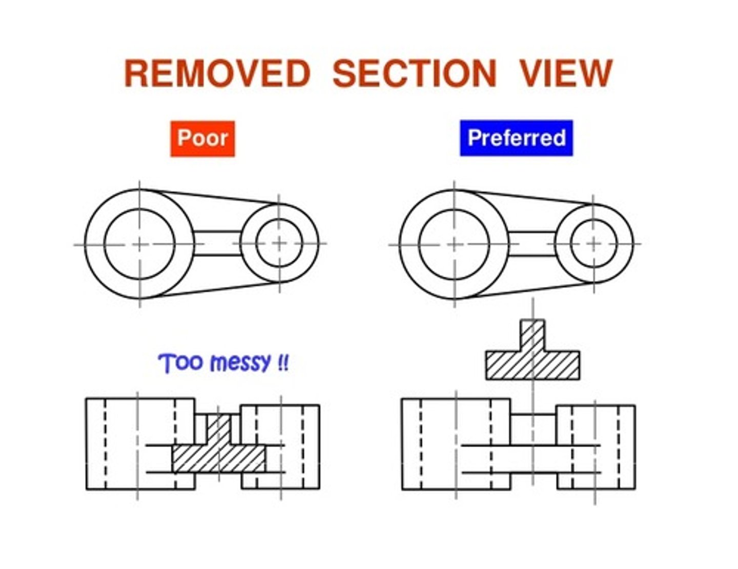
Removed Section
A section view that is not in direct projection alignment but is placed elsewhere on the drawing sheet.
Basically: When a section cut out is done, but looks way too messy, the "Removed section" feature allows u to take the cross-section (ONLY the cross section and not an entire drawing) out elsewhere in the drawing paper for deeper examination.
Revolved Section
A cross-section that is rotated 90 degrees and superimposed on the orthographic view.
Basically: Instead of putting the cross-section elsewhere on the paper, you put it direction on the view you were already working from.
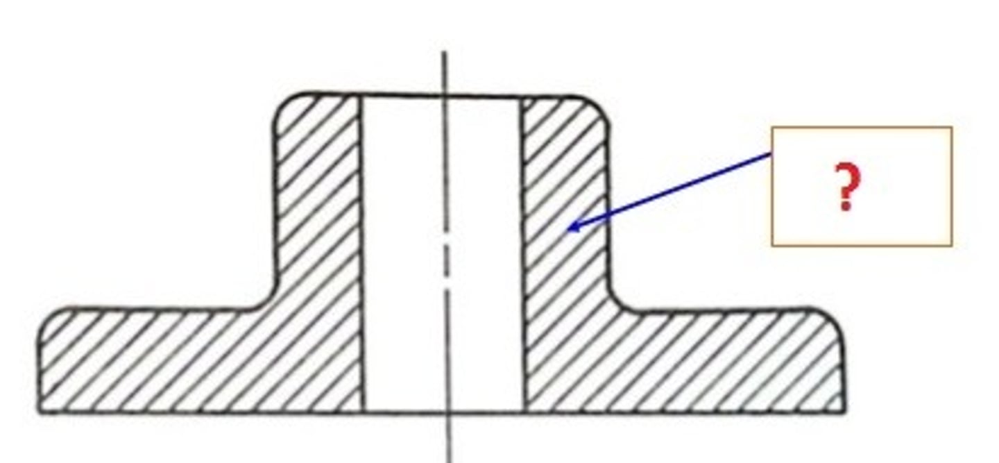
Section Lines
The patterned shading (hatching) used to indicate the surfaces of the object that have been cut by the cutting plane.
Section View
A view that presents an object as if a portion has been hypothetically cut away to reveal interior details.
Viewing Direction
The direction from which the section is observed, shown by arrows on the cutting plane line.
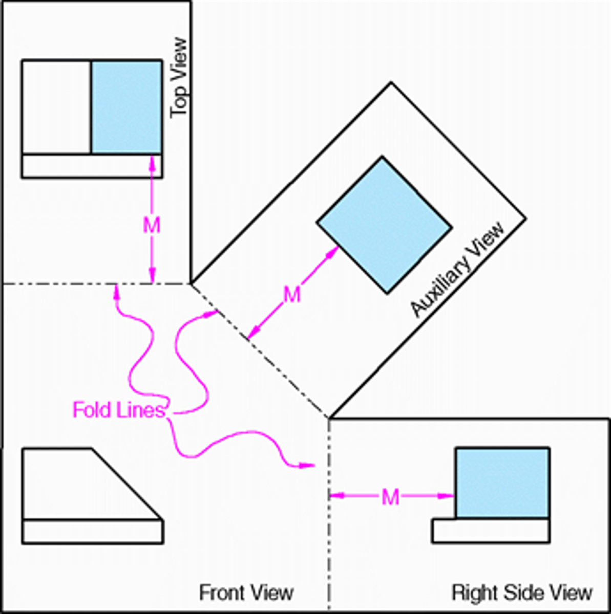
Auxiliary Views
A view projected onto a plane that is not parallel to the principal projection planes, used to show the true shape and size of an inclined or oblique surface.
Edge View (of a plane)
A view in which a given surface appears as a line.
Foreshortened
Appearing shorter than its true length because it is not parallel to the plane of projection.
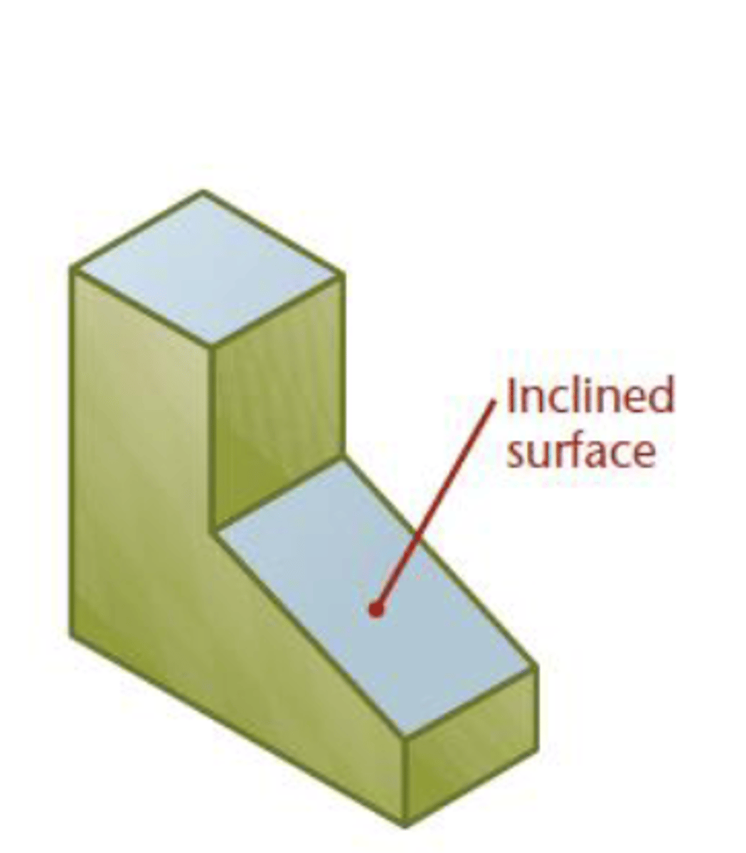
Inclined Surface
A plane that appears as an edge in one primary view but is foreshortened in the others.
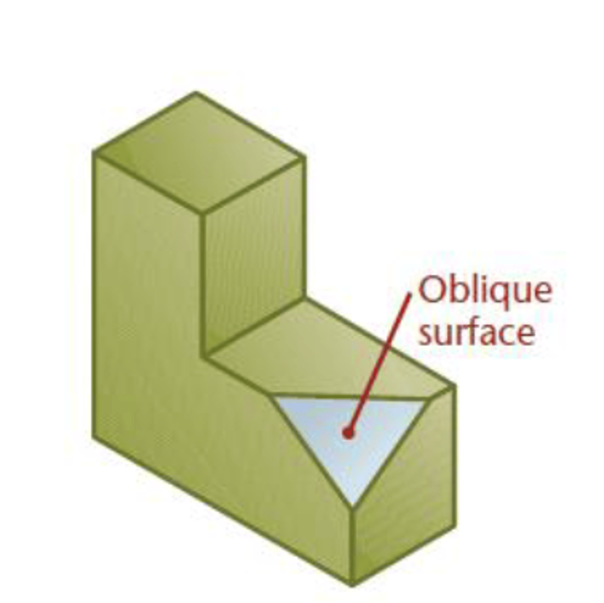
Oblique Surface
A plane that DOES NOT APPEAR AS AN EDGE in any of the six principal views (front, top, right, left, bottom, back).
If you google it, you'll understand immediately what I mean..
Projection Ray
A line perpendicular to the projection plane, used to transfer geometry between views.
Basically: Tangential lines that emerge from a 3D model onto a 2D plane to make a profile
Reference Line
A line representing the intersection (hinge/fold line) between two projection planes. Critical for constructing auxiliary views.
Related Views
The two adjacent views used to project from when creating an auxiliary view.
Basically: Adjacent views are views next to each other.... Related views are views that are connected by projection lines...
True Shape (of a plane)
The actual shape and size of a surface, shown in a view where the line of sight is perpendicular to it.
Basically: Directly looking at the inclined surface where your view is directly perpendicular to its plane
ANSI Y14.5
The industry standard that outlines uniform practices for displaying and interpreting dimensions and tolerances.
Arrowhead
A symbol at the end of a dimension line or leader to indicate its extent.
Baseline Dimensioning
A system where each feature is located from a common origin or datum.
Chain Dimensioning
A system where features are located sequentially from one to the next.
Contour Dimensioning
Placing dimensions in the view where the contour or shape of the feature is best shown.
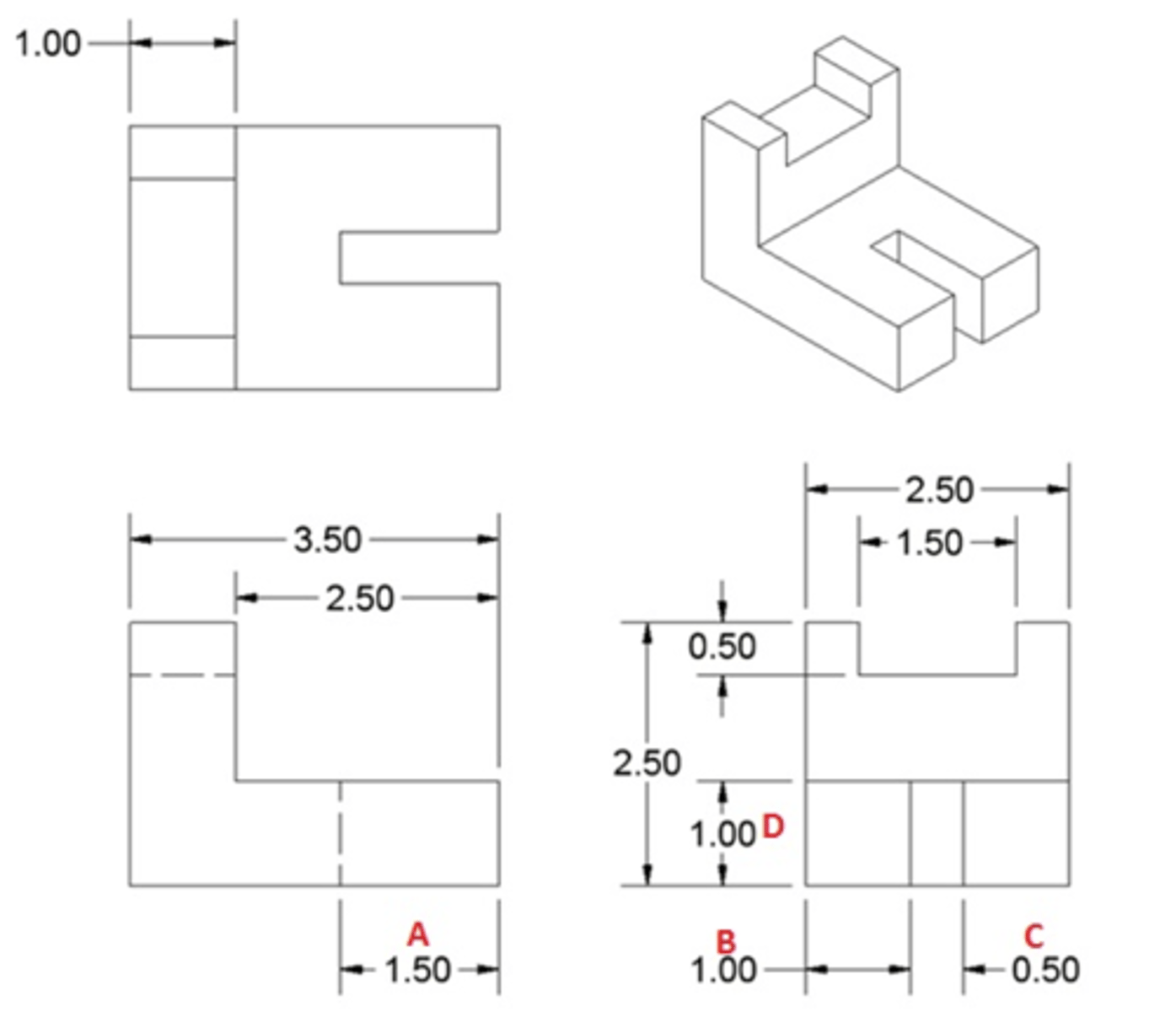
Contour Rule
The practice that each dimension should be placed in the view where the contour shape is best shown.
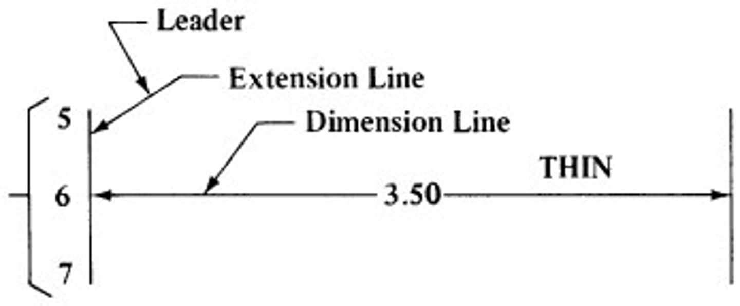
Dimension
A numerical value defining the size, location, or other characteristic of a feature.
Dimension Line
A thin, solid line that terminates with arrowheads, indicating the direction and extent of a dimension.
Notice how "Arrowheads" is plural...
Extension Line
A thin, solid line that extends from a feature on the object to the dimension line.
Leader
A thin, solid line that connects a note, symbol, or dimension to a specific feature.
Basically: The difference between a dimension line and a leader is that---- a dimension line is the line used to label a gap... while a leader is a line that is used to point toward something
Location
A dimension associated with the position
of a feature on a part
Size
The general term for the size of a feature, such as a hole, cylinder, or set of opposed parallel surfaces.
Tolerance
The total amount a specific dimension is permitted to vary.
Allowance
The minimum clearance --or-- maximum interference between mating parts.
Basically: the theoretically/mathematically tightest breathing room possible between a shaft and a hole
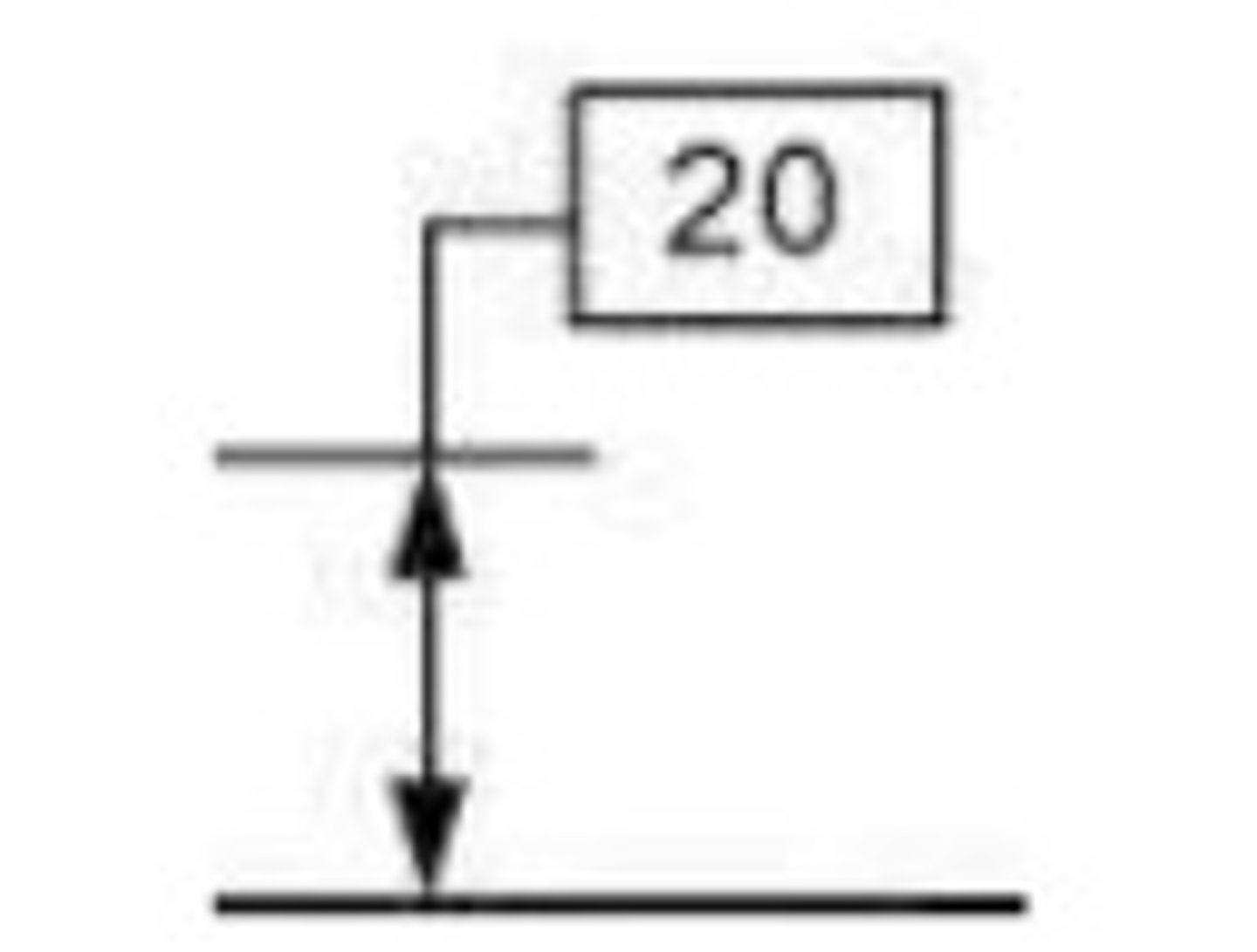
Basic Dimension
A theoretically exact dimension. It is identified by a box and locates the perfect position of a feature from a datum.
Clearance Fit
A fit where there is always space between two mating parts.
Think of allowance as the theoretical min and max amount of gap between two mating parts... clearance is the ACTUAL gap once manufactured
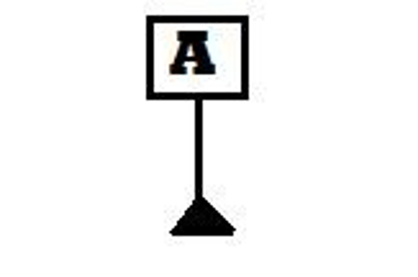
Datum
A theoretically exact plane, axis, or point established by real features on an object, used as a reference.
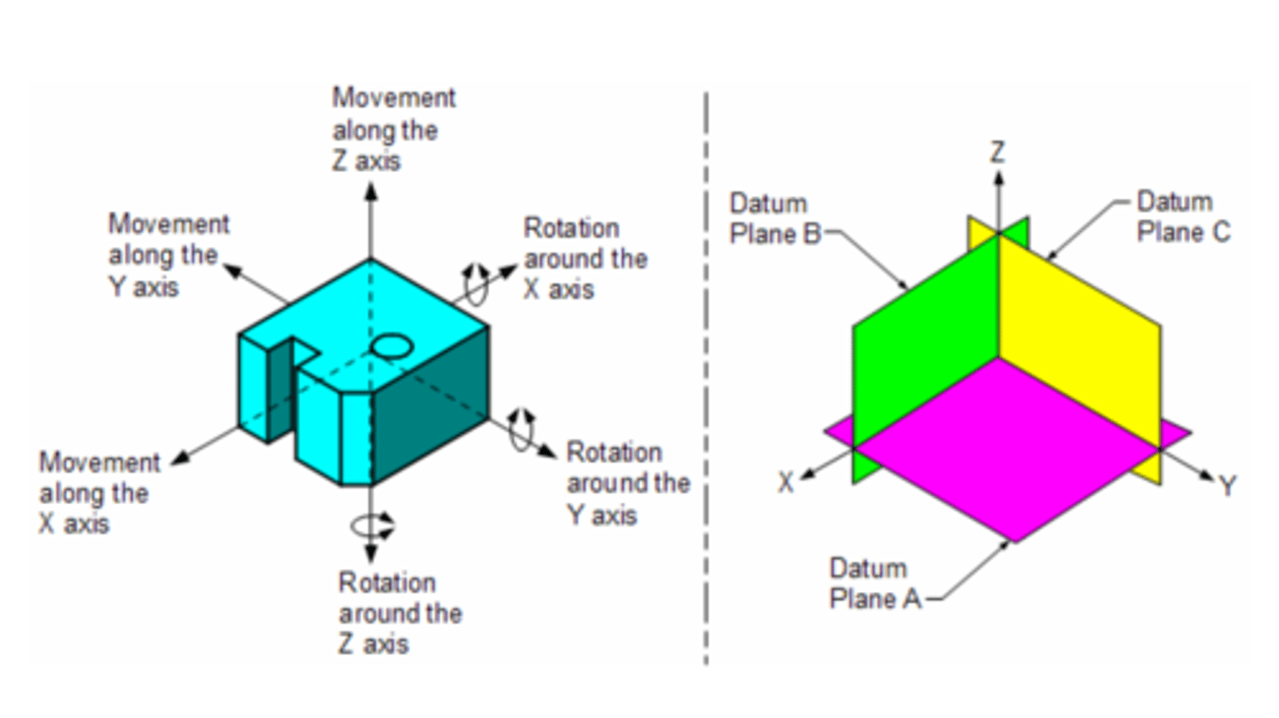
Datum Reference Frame
A system of three mutually perpendicular planes used as the coordinate system for Geometric Dimensioning and Tolerancing (GD&T).
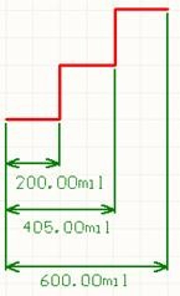
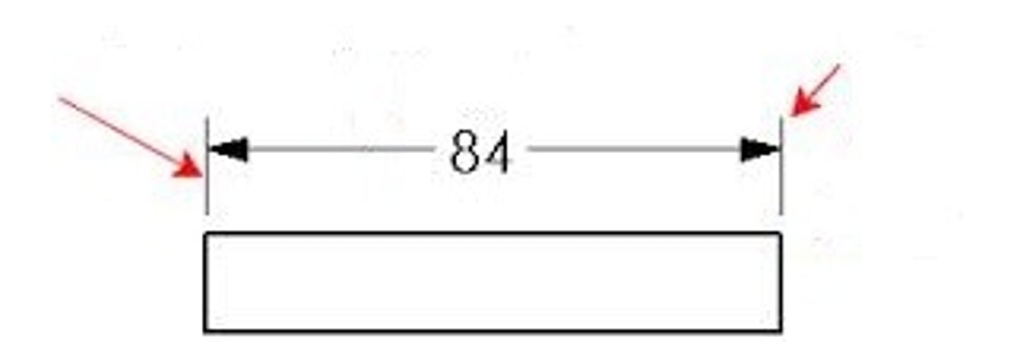
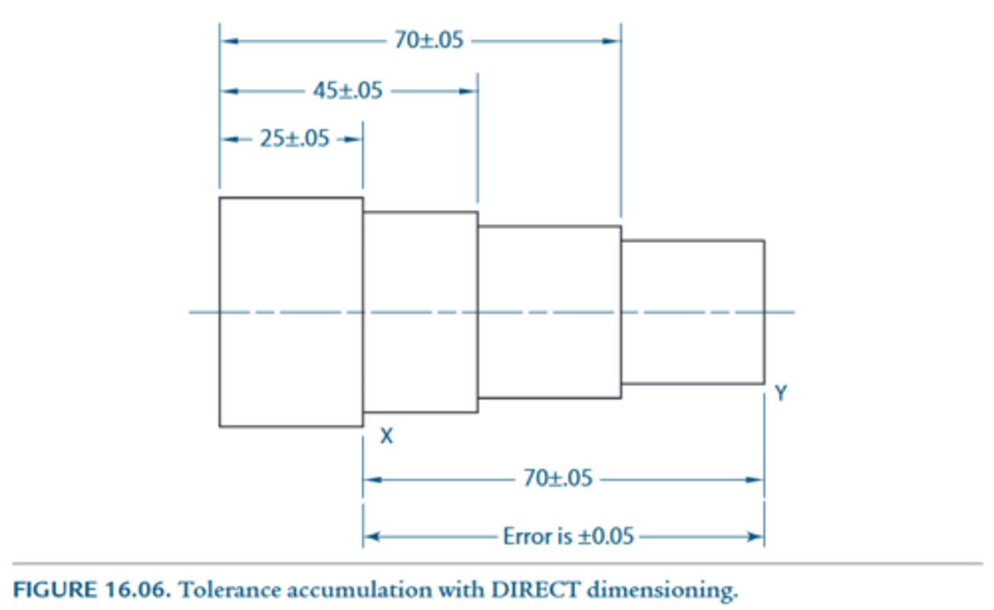
Direct Dimensioning
Dimensioning between two key points directly to minimize tolerance accumulation.
Basically: instead of baseline or chaining together multiple dimension labels, you go from one end to another direction to reduce tolerance accumulation... its "direct"--- refer to the bottom dimensioning from the attached image
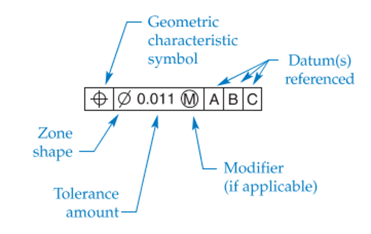
Feature Control Frame
A rectangular box that contains the geometric characteristic symbol, tolerance value, and datum references for a feature.
Feature with Size
A feature associated with a size dimension, such as a hole, cylinder, or the distance between two parallel surfaces.
Its kinda complicated, but do you remember normal forces from physics? BASICALLY::: If the two point you are measuring, the normal vectors from the two distinct surfaces point opposite to each other---- feature WITH size...
If the normal vectors point towards the same direction--- feature WITHOUT size..
Feature without Size
A feature like a planar surface, where the normal vectors point in the same direction.
Functional Gage
A physical tool built to quickly verify that a specific GD&T condition is within tolerance.
The textbook however specifies that its used to inspect the straightness of an axis
Geometric Dimensioning and Tolerancing (GD&T)
A precise system for defining the form, orientation, and location of part features within tolerance zones.
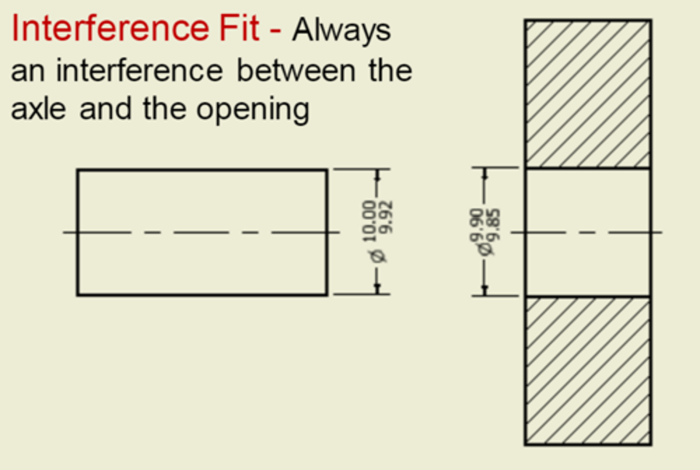
Interference Fit
A fit where the shaft is larger than the hole, requiring force for assembly.
Maximum Material Condition (MMC)
The condition where a feature of size contains the maximum amount of material within its size limits (e.g., largest shaft, smallest hole).
Basically: the tightest possible fit
Statistical Tolerancing
A method of assigning tolerances based on statistical analysis rather than worst-case stack-up.
(We dont rlly do this in practice... not at least in ME9, but just know about the concept)