IS201 Analysis
1/178
There's no tags or description
Looks like no tags are added yet.
Name | Mastery | Learn | Test | Matching | Spaced | Call with Kai |
|---|
No analytics yet
Send a link to your students to track their progress
179 Terms
Purpose of Requirements Determination
The purpose is to convert a high-level explanation of business needs into a precise list of system requirements
5 examples of requirements-gathering techniques
-Interviews
-Quationnaires
-Observation
-Joint application development (JAD)
-Document analysis
Process of Interviews
-Step 1: Select people and schedule
-Step 2: Design questions
-Step 3: Prepare for interview
-Step 4: Conduct interview
-Step 5: Do a follow up
Interview question types
1. Close ended (yes/no)
2. Open ended (needs details to answer)
3. Probing (go deeper)
Interviewing strategies
-High level: very general questions
-Medium-level: Moderately specific questions
-Low-level: Very specific question
Process of conducting questionnaires
-Step 1: Select participants
-Step 2: Design the questionnaire
-Step 3: Administer questionnaire
-Step 4: Conduct a follow-up
Guidelines for good questionnaire design
-avoid crowding the page
-No abbreviations
-Avoid biased questions
-pretest for confusion
-provide anonymity
Joint Application Development / JAD
A session where employees meet, sometimes for several days, to define or review the business requirements for the system.
Document Analysis
Provides information about the "as is" system through reviewing technical documents and typical user documents
Alternative techniques
-Concept maps
-User stories, Story cards and task lists
Requirements analysis strategy
strategy that structures gathered data to identify and improve specific processes
8 Requirements analysis strategies
-Problem analysis
-Root cause analysis
-Duration analysis
-Activity based costing
-informal benchmarking
-outcome analysis
-technology analysis
-activity elimination
Problem analysis - requirement analysis strategy
A scenario where users identify problems with current process/system and explain how they would solve them
Root cause analysis - requirement analysis strategy
Focuses on identifying the cause of a problem. involves creating a prioritized problem list, determining causes, and developing solutions based on those causes
Duration analysis - requirements analysis strategy
Determines the time required to complete each step in a business process
Activity-based costing - requirements analysis strategy
Determines the cost required to complete each step in a business process
Technology analysis - requirements analysis strategy
The process of searching and listing technology solutions, then evaluating how each could be applied to the business and what benefits they would provide
Common problems in determining requirements
-No access to correct users
-Unknown requirements cause delays and cost overruns
-Difficulty in validating requirements
-Lack of stakeholder involvement
-Insufficient time for thorough analysis
Functional requirements
identifies processes a system must perform to complete needed tasks and focuses on user requirements. These requirements are captured in a functional requirements specification document or in the systems proposal document
Non-Functional requirements
identifies behavioral properties the system must have to operate efficiently, securely and reliably and focuses on user expectation and experience
What functional requirements describe
-Data processing
-Use case
-Used technology
System proposal template
Combines all material created in the requirements and analysis phases of the SDLC
7 Sections of a systems proposal
-Executive summary of all info
-The system request
-Workplan
-Feasibility analysis
-Requirements definition
-Functional models (Structural and behavioural)
-Appendices
Types of non-functional requirements
Performance requirements and security requirements
Use Case
Describes basic system functions in terms of what the user can do and how the system responds. Each use case describes exactly one function.
Actor
Someone who uses the system to achieve a particular goal
Primary actor
user who initiates the use of the system - left side
Secondary actor
User who responds or reacts after an action is performed, provides support, or receives output - right side
An include relationship
Represents the inclusion of the functionality of one use case within another, happens every time a Base Use Case is executed

An extend relationship
Represents the extension of the use to include optional behaviour. Happens sometimes when a certain criteria is met

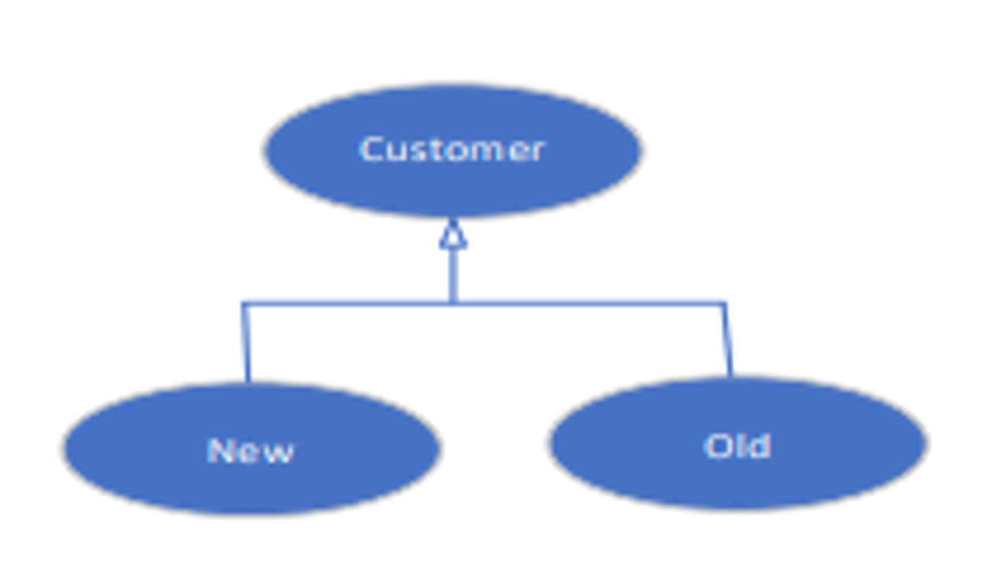
Generalization relationship
AKA inheritance, breaks a general use case into specialized use cases
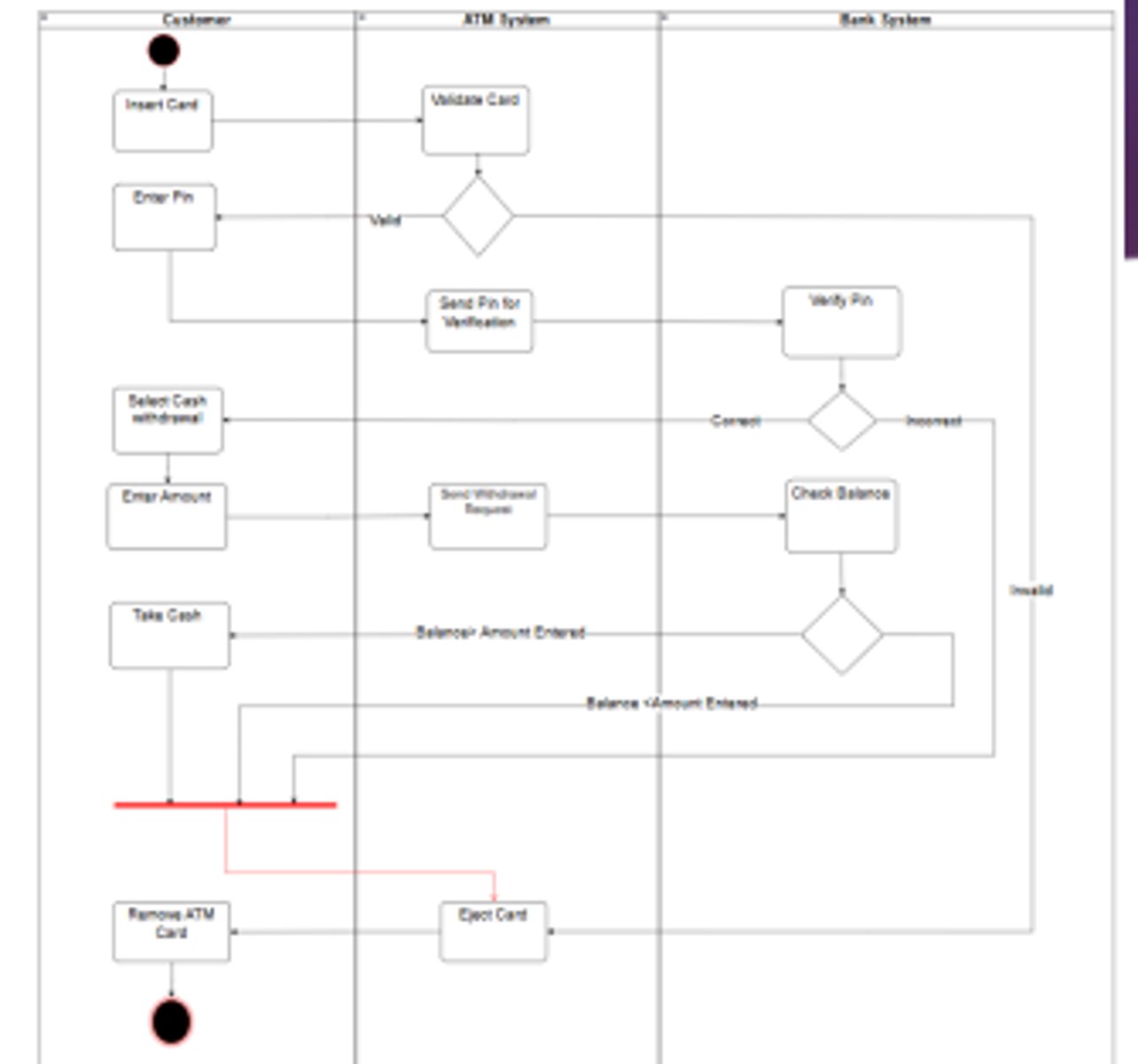
Activity Diagram
Models how a business operates through business processes. Used to illustrate movement of data between activities
Elements of activity diagram
Activity, Object Node, Control Flow, Control Nodes
Object Node - Activity diagram element
Represents a flow of information from one activity to another
Control flow - Activity diagram element
Models the execution paths
Control Node Types - Activity diagram element
-Initial node
-Final activity node
-Decision node
-Merge node
-Fork node
-Join node
Activity
Represents a set of actions
initial Node
The beginning of a set of actions

Final Node
Stops all flows in an activity

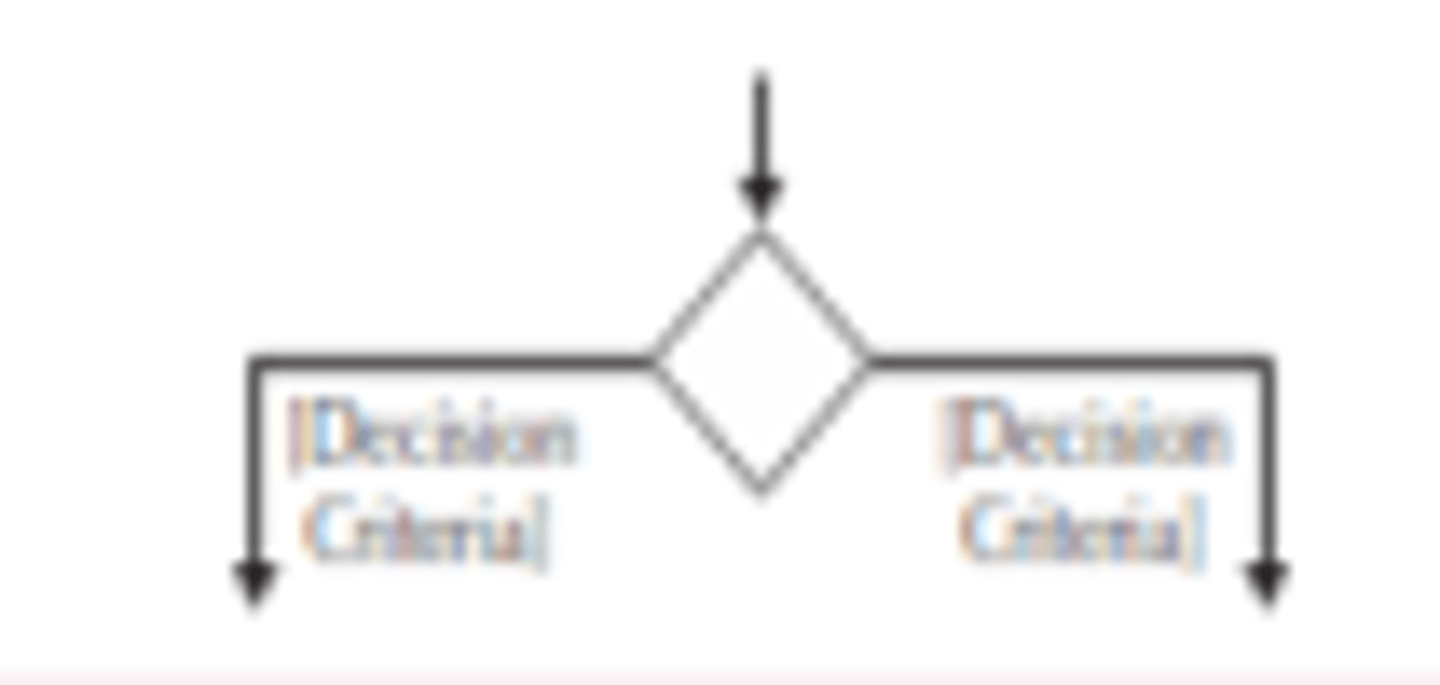
Decision Node
Represents a test condition
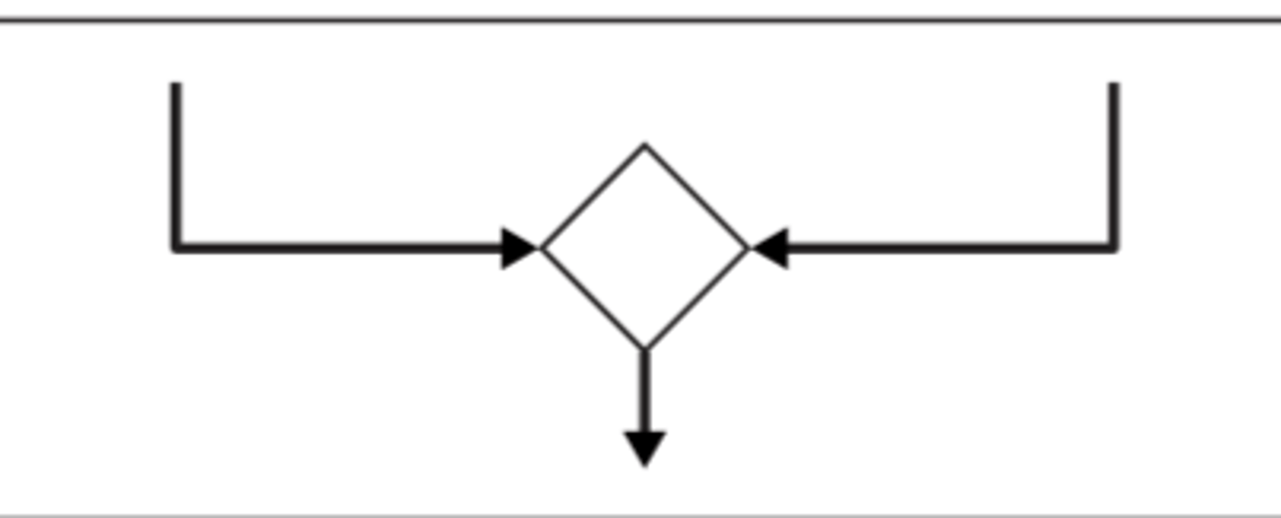
Merge Node
Used to bring back different decision paths that were created using a decision node
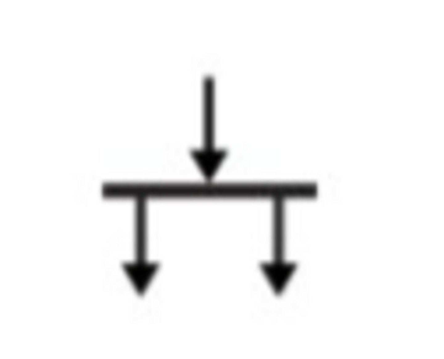
Fork Node
Used to split behaviour into a set of concurrent flows of activities for actions
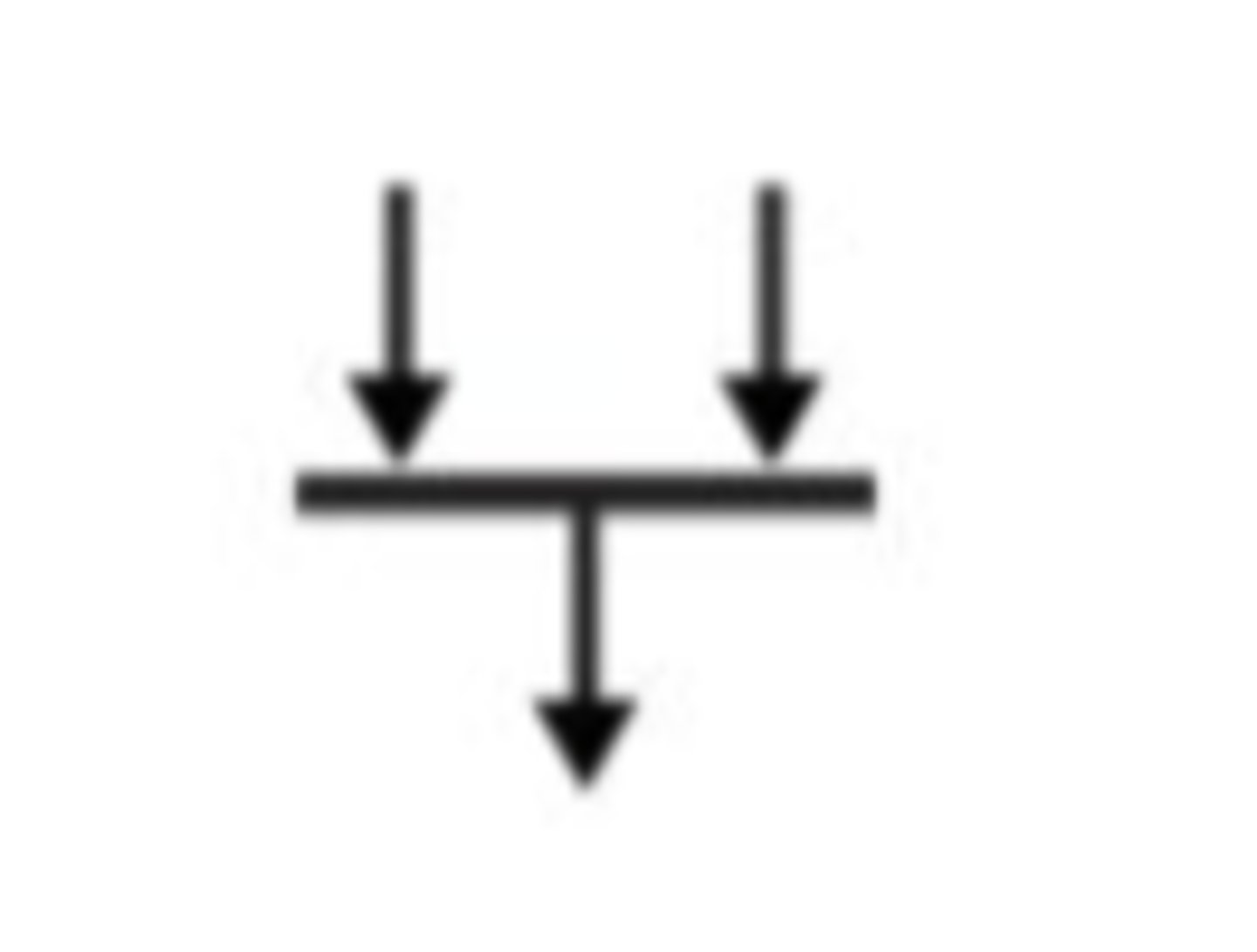
Join Node
Used to bring back together a set of concurrent flows of activities or actions
Swimlane
A way to break an activity diagram into rows or columns. Assigns activties to specific actors or systems
Structural diagrams
Describes the structure of a system over time and focuses on the class level
Behavioural diagrams
Describes the behaviour of a system and focuses on the object level
Interaction diagrams
A behavioral model used to visualize interactive options of a system. Models interactions between objects and the system at the object level, describing the flow of messages within the system
Types of interaction diagrams
-Sequence diagram: emphasizes the message sequence
-communications diagrams: emphasize the message flow
Sequence diagram elements
-Actor
-Object
-Lifeline
-Execution occurrence
-Message
-guard condition
-Frame
Communication diagram elements
-Actor
-Object
-Association
-Message
-Guard condition
-Frame
Lifeline: Element of sequence diagram
Denotes the life of an object during a sequence
Execution occurrence: Element of sequence diagram
Denotes when an object is sending or receiving messages

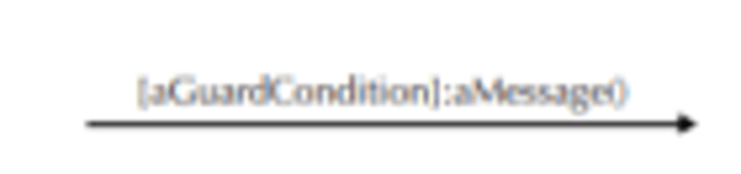
Guard condition: Element of both diagrams
Represents a test that must be met for the messages to be sent
Purpose of sequence diagram
Shows how objects interact over time and is used to understand the message order
Purpose of the communication diagram
Shows how objects communicate with each other using numbers to indicate the flow of messages. Used to understand the system structure.
Purpose of State Machine
Shows how an object changes state over time, used to understand the state of the object
Crude analysis
Used to describe five basic operations that one can perform on data in a system
The five basic operations of CRUDE
-Create
-Read
-Update
-Delete
-Execute
Structural model
Describes the structure of objects that supports the business processes or system
Static Structural model
Represents the system's structure at a specific point in time
Dynamic Structural model
Represents the system's behaviour over time
Basic elements of structural model
-Class
-Attributes
-Methods/operations
-Relationships
Types of methods/operations
-Constructor: creates an object
-Query: Makes information about the state of an object available
-Update: changes values of some or all of an object's attributes
-Destructor: deletes or removes an object
Types of relationships in a structural model
-Generalization
-Aggregation
-Association
-Composition
-Multiplicity
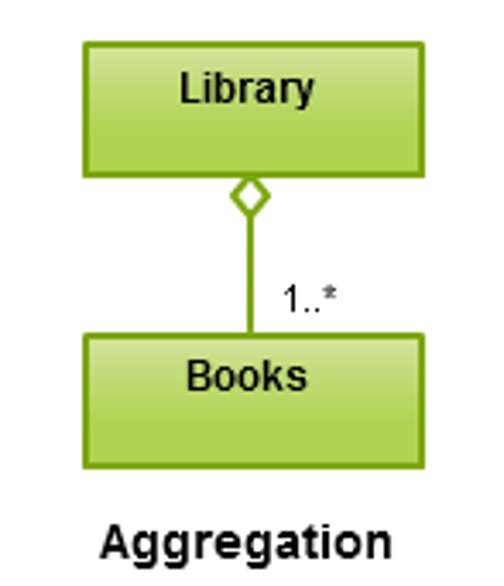
Aggregation relationship
A "whole-part" relationship where one class contains or is composed of other classes. Represents a "has-a" relationship
Association relationship
structural relationship indicating that one class is connected to or knows about another class. Represents any general connection between objects.
Composition relationship
stronger form of aggregation where the "part" cannot exist independently from the "whole."

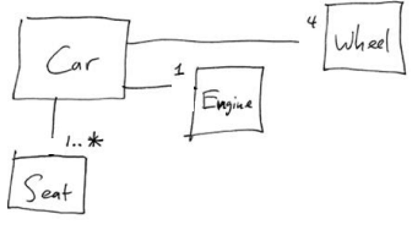
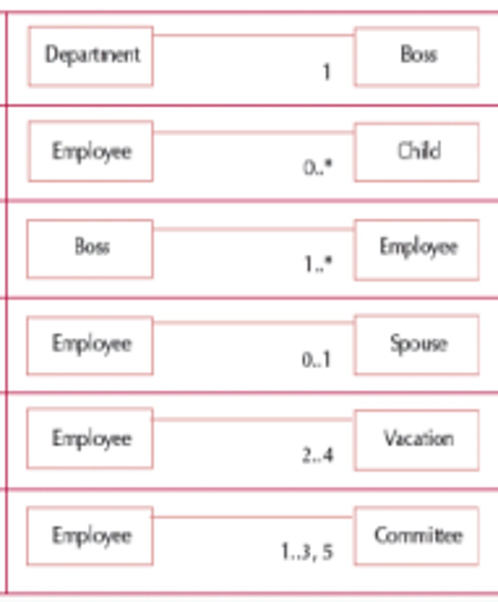
Multiplicity relationship
Relationship that indicates how many of one class are related to another class
Object identification approaches
-Textual analysis
-Brainstorming
-Common object lists
-Patterns
Textual analysis
Reviews use case diagrams to identify objects. Nouns become classes and verbs become methods
Brainstorming
Facilitator leads a group to share ideas in comfortable setting then participants identify classes and attributes
Common object lists
A technique where analysts set aside use cases and instead identify objects based on the business domain
Patterns
relatively new area in OOSAD. Reusable tools for collaborating classes that provide solutions ot common problems
Class responsibility collaboration card
A brainstorming tool used in the design of object-oriented system and is most popular
Index cards
Used to document the responsibilities and collaborations of a class
Types of responsibilities in a class
Knowing responsibility and doing responsibility
Knowing responsibility
Things that an instance of a class must be capable of knowing
Doing responsibility
Things that an instance of a class must be capable of doing
Key people involved in Design Phase
Senior Developers, Architects
Key people involved in Deployment Phase
-Entire Project team
-Client
Step 7 of SDLC: Maintenance Phase
Involves software upgrades, repairs, and fixing defects. Maintenance is performed according to the agreed Service Level Agreement (SLA) Document.
Key people in Maintenance Phase
-Developers
-Project Manager
-Business, System and Quality Analysts
-Clients
System Analysts
A role that creates value for the organization and act as agents of change by identifying ways to improve the organization as well as motivating and training others
Business Analyst
Focuses on business issues and improves business processes. Designs new processes/policies with the System Analyst and is involved mostly in the requirements phase
Infrastructure Analyst
Focuses on technical issues of how the system interacts with hardware, software, networks, and databases. Ensures system conforms to organizational standards and identifies needed infrastructure changes
System Development Life Cycle / SDLC
A planning process for developing information systems that defines WHAT the system should do and HOW its components will work together.
System development challenges faced by organisations
-Poor quality of info to develop a system
-Lack of adequate resources
-Lack of information accessibility
-Poor integration of legacy systems
-Projects are abandoned before completion
SDLC Process
-Step 1: Requirement phase
-Step 2: Analysis phase
-Step 3: Design phase
-Step 4: Development phase
-Step 5: Testing phase
-Step 6: Deployment phase
-Step 7: Maintenance phase
Step 1 of SDLC: Requirement Phase
most important SDLC phase. Business Analysts gather client needs, document them in a Business Requirements Document (BRD), then define and get client approval for system requirements.
Key people involved in Requirement Phase
Project Manager, Business analyst, Senior developers
Step 2 of SDLC: Analysis Phase
team gathers information about the problem. Produces the System Requirements Specification (SRS) document, containing all product requirements, which must be approved by the client.
Key People involved in Analysis Phase
Project Manager, Systems Analyst, Senior Managers
Step 3 of SDLC: Design Phase
Defines how each system feature will work, including hardware, software and network infrastructure. via:
-High-level design documents, discussing system architecture
-Low-level design documents, discussing internal program logic
Step 4 of SDLC: Coding / Development Phase
The longest SDLC phase where developers write code in units/modules using the chosen programming language, Delivering the actual system and its source code
Key People involved in Development Phase
-Senior Developers
-Developers
-Systems Analyst
Step 5 of SDLC: Testing Phase
where the system is tested for bugs manually or automatically before deployment. Ensures the system works holistically and is error-free. Testing approach is defined in the Testing Life Cycle document.
Key people involved in Testing Phase
-Business Analysts
-Quality Analysts
-Developers
-Software Testers
Step 6 of SDLC: Deployment Phase
where the system is put into production and handed over to the client. Includes deployment preparation, product deployment, transferring ownership, and closing the deployment phase.
Change Management Analyst
Focuses on people and management issues during system installation. Ensures documentation, user training and support are available
Project Manager
Develops project plan, ensures on-time/budget completion, manages team/resources, and is accountable for execution. Works throughout all SDLC phases.