Chapter 9 - Counters
1/68
There's no tags or description
Looks like no tags are added yet.
Name | Mastery | Learn | Test | Matching | Spaced | Call with Kai |
|---|
No analytics yet
Send a link to your students to track their progress
69 Terms
____ 1. There are two types of PLC counter instructions. t/f
f
____ 2. The content of an accumulated register in the count down instruction decrements whenever there is a low-to-
high counter input switch transition. t/f
t
____ 3. The counter done bit for the counter instruction C5:1 is addressed as C5:1/DN. t/f
t
____ 4. The content of an accumulated register in the count up instruction increments whenever there is a low-to-high
counter input switch transition. t/f
t
____ 5. Internal bit C5:0/CD is on when the input to the count up instruction C5:0 is closed. t/f
f
6. The accumulated value for counter instruction C5:0 is in the ______________________________ register.
C5:0.ACC
7. The preset value for counter C5:0 is in register ______________________________.
C5:0.PRE
8. You must use the ______________________________ instruction to reset a count up instruction
RES
9. The content of an accumulated register for the count up instruction is ______________________________
for every low-to-high counter input switch transition.
incremented
10. The content of an accumulated register for the count down instruction is ______________________________
for every low-to-high counter input switch transition.
decremented
11. The counter done bit for count up instruction C5:0 is addressed as ______________________________.
C5:0/DN
12. When the content of the count up registers C5:0.PRE and C5:0.ACC are equal, the
______________________________ coil energizes.
done
13. The counter done bit for the count down instruction C5:0 is addressed as
______________________________.
C5:0/DN
14. When an input instruction to the count down instruction C5:0 is closed, the
______________________________ coil energizes.
count down
15. Data files C5:0 through C5:255 can be used for ______________________________ instructions.
counter
1) Which of the following statements is NOT correct? 1) _______
A) All AB timer instructions operate in nearly an identical fashion.
B) All AB timers are more accurate than mechanical and electronic timers.
C) The accuracy of PLC timers can be affected by short scan time.
D) The TON, TOF and RTO timers are all output instructions.
F) D and C
F
2) A TON timer rung is active and the ACC value is less than the PRE value, so the ________ timer
bits are true.
A) Both the EN and TT
B) Only the TT
C) Only the EN
D) Both the TT and DN
A
3) A TON timer rung is active and the ACC value is greater than the PRE value, so the ________
timer bits are true.
A) Only the TT
B) Only the EN
C) Both the EN and DN
D) Both the EN and TT
C
4) A TOF timer rung is false and the ACC value is less than the PRE value, so the ________ timer
bits are true.
A) Only the DN
B) Only the TT
C) Both the EN and TT
D) Both the TT and DN
D
5) An RTO timer rung is false and the ACC value is greater than the PRE value, so the ________
timer bits are true.
A) Both the TT and DN
B) Both the EN and TT
C) Only the TT
D) Only the DN
D
6) An RTO timer rung is true and the reset instruction rung for the timer is true, so 6) _______
A) The ACC is reset to zero and the DN bit is false.
B) The ACC and PRE are reset to zero and the DN bit is false.
C) All timer bits are false and the ACC is reset to zero.
D) The ACC is reset to zero, the DN bit is false, and the EN bit is true.
D
7) An RES used with an RTO timer ________. 7) _______
A) Must be true for more than one scan for the reset action to occur
B) Can only be active after the RTO timer has completed the timing process
C) Has the same address as the RTO timer
D) Will not function if the RTO rung is active
C
8) Which one of the following SLC 500 counter statements is NOT true? 8) _______
A) 1000 counters are available in file C5.
B) Additional counters are available in the user defined file area.
C) File, C5, is used for all counters, and File ID numbers are unique.
D) Counters are virtual software devices, so the number is only limited by PLC memory.
D
9) The ________ counter bit is only true when the ACC value is equal to or greater than the PRE value,
9) _______
A) UN
B) DN
C) OT
D) CU
B
10) The ________ counter bit is only true when the up counter rung is true. 10) ______
A) CU
B) DN
C) UP
D) CD
A
11) The ________ counter bit is only true when the down counter decrements below maximum negative value.
11) ______
A) UN
B) DN
C) NE
D) CD
A
12) The ________ counter bit is only true when the up counter increments above maximum positive
value.
12) ______
A) UN
B) CU
C) OV
D) OT
C
13) In addition to the decimal number system, the number systems used most often in PLC opera-
tion and programming are ________.
13) ______
A) Octal and BCD
B) Binary and octal
C) Binary and hexadecimal
D) BCD and hexadecimal
C
14) Which one of the following statements on SLC 500 module addressing is NOT true? 14) ______
A) The structure begins with either an I for inputs or an O for outputs and a colon (:) is used as
a delimiter between the I or O and the module slot number.
B) The word number is only needed if the addressed word is not 0.
C) A forward slash (/) delimiter separates the word number from the final two digits for the
terminal number.
D) The slot number is followed by the forward slash (/) before the word number.
D
15) The address for bit 10 in word 5 for the SLC 500 is ________. 15) ______
A) B3:5/10
B) B3:10/5
C) B:3.5/10
D) BIT:3.10/5
____ 1. Which of the following PLC counter types is available to Allen-Bradley advance PLCs?
A. Counter up (CTU)
B. Counter down (CTD)
C. High speed counter (HSC)
D. All of the above.
D
____ 2. How many registers does each PLC counter instruction have?
A. One
B. Two
C. Three
D. Four
C
____ 3. How many flag bits are available to the PLC programmer for programming PLC counter instruction registers?
A. Two
B. Four
C. Five
D. Six
A
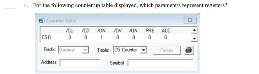
____ 4. For the following counter up table displayed, which parameters represent registers?
A. CU, CD, and OV
B. CU, CD, and DN
C. CU, PRE, and ACC
D. PRE and ACC
D
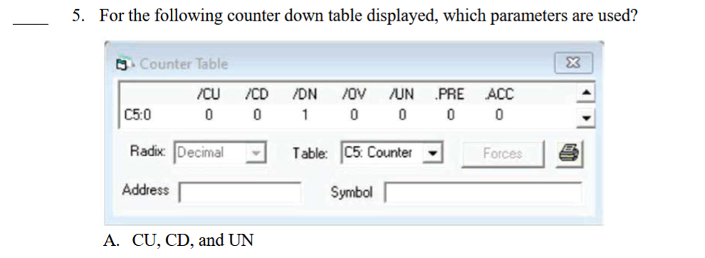
___ 5. For the following counter down table displayed, which parameters are used?
A. CU, CD, and UN
B. CD, DN, and UN
C. CU, CD, and OV
D. CD, DN, and OV
B
____ 6. How many counter instructions can an Allen-Bradley PLC have?
A. 250
B. 100
C. 256
D. 255
C
____ 7. When the RES instruction associated with a counter up is energized, its ____.
A. PRE register is set to zero
B. ACC register is set to zero
C. DN bit is energized
D. ACC register increments
B
____ 8. When the RES instruction associated with a counter down is energized, its ____.
A. DN bit is energized
B. ACC register increments once
C. ACC register decrements once
D. PRE register is set to zero
A
____ 9. In a counter up register, when its preset register is equal to its accumulated register, its ____.
A. DN flag bit is energized
B. OV flat bit is energized
C. UN flag bit is energized
D. None of the above.
A
____ 10. In a counter up register, when its present register is greater than its accumulated register, its ____.
A. DN flag bit is de-energized
B. OV flag bit is energized
C. DN flag bit stays energized
D. accumulated register is reset to zero
A
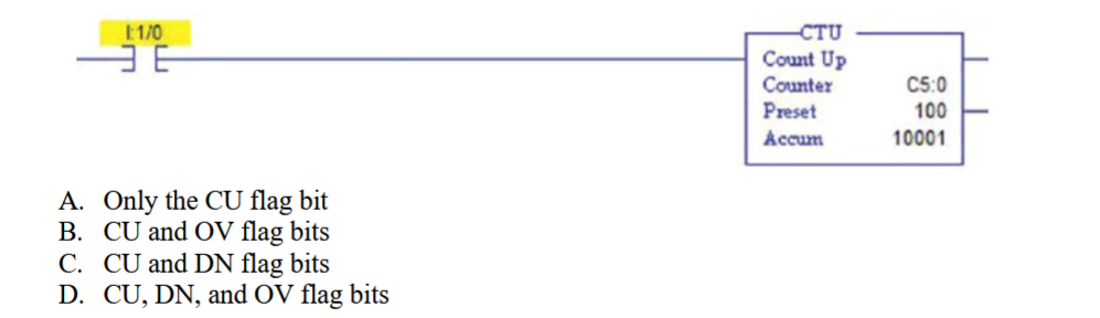
____ 11. Which counter up (CTU) flag bits are energized in the following ladder logic diagram?
A. Only the CU flag bit
B. CU and OV flag bits
C. CU and DN flag bits
D. CU, DN, and OV flag bits
C
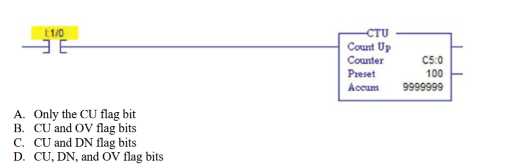
___ 12. Which counter up (CTU) flag bits are energized in the following ladder logic diagram?
A. Only the CU flag bit
B. CU and OV flag bits
C. CU and DN flag bits
D. CU, DN, and OV flag bits
B
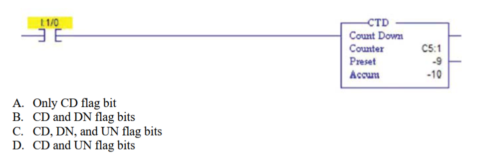
____ 13. Which counter down (CTD) flag bits are energized in the following ladder logic diagram?
A. Only CD flag bit
B. CD and DN flag bits
C. CD, DN, and UN flag bits
D. CD and UN flag bits
A
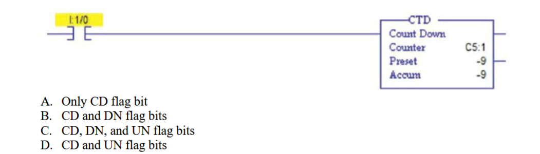
____ 14. Which counter down (CTD) flag bits are energized in the following ladder logic diagram?
A. Only CD flag bit
B. CD and DN flag bits
C. CD, DN, and UN flag bits
D. CD and UN flag bits
B
___ 15. Which counter up (CTU) flag bit is energized when input to CTU is on?
A. DN
B. CD
C. CU
D. UP
C
____ 16. Which counter down (CTD) flag bit is energized when input to CTD is on?
A. CU
B. UN
C. DN
D. CD
D
____ 17. Which counter flag bit is energized when the counter accumulator register decrements below the maximum
value?
A. DN
B. CD
C. NEG
D. UN
D
____ 18. The update accumulator bit (UA) is used with ____ instructions.
A. counter up (CTU) counter
B. counter down (CTD) counter
C. high speed counter (HSC)
D. All of the above.
C
____ 19. Which counter flag bit is energized when the counter accumulator register increments above the maximum
value?
A. DN
B. CU
C. OV
D. POS
C
____ 20. Which of the following statements is false?
A. A low-to-high input transition will result in CTU accumulator register increment once.
B. A low-to-high input transition will result in CTD accumulator register to increment once.
C. A low-to-high input transition will result in CTD accumulator to decrement once.
D. Both A and B are incorrect.
B
____ 21. Internal bit C5:0/CU is on when the input to the count up instruction C5:0 is open.T/F
F
____ 22. Count up and count down are the counter instructions available in PLCs. T/F
T
____ 23. The content of an accumulated register in the count down instruction decrements whenever there is a low-to-
high counter input switch transition.
T
____ 24. The accumulated register for counter instruction C5:0 is addressed as C5:0.ACC.
T
____ 25. The counter done bit for the counter instruction C5:1 is addressed as C5:1/DN.
T
____ 26. The count up instruction C5:0 in a fixed SLC 500 PLC uses two 16-bit registers.
F
____ 27. The content of an accumulated register in the count up instruction increments whenever there is a low-to-high
counter input switch transition.
T
____ 28. Internal bit C5:0/CD is on when the input to the count up instruction C5:0 is closed.
F
29. The accumulated value for counter instruction C5:0 is in the ______________________________ register.
accumulated
30. The preset value for counter C5:0 is in register ______________________________.
C5:0.PRE
31. You must use the ______________________________ instruction to reset a count up instruction.
RESET
32. The content of an accumulated register for the count up instruction is __________________________ for
every low-to-high counter input switch transition.
incremented
33. The content of an accumulated register for the count down instruction is __________________________ for
every low-to-high counter input switch transition.
decremented
34. The counter done bit for count up instruction C5:0 is addressed as ______________________________.
C5:0/DN
35. When the content of the count up registers C5:0.PRE and C5:0.ACC are equal, the
______________________________ coil energizes.
done
36. You must use the ______________________________ instruction to reset a count down instruction.
RES
37. The counter done bit for the count down instruction C5:0 is addressed as
______________________________.
C5:0/DN
38. The content of an entire section of a conveyor can be known at any one time by placing two
______________________________ on the conveyor.
proximity sensors
39. Data files C5:0 through C5:255 can be used for ______________________________ instructions
counter