Materials T7 - Functional Properties
 Call Kai
 Learn
Learn Practice Test
 Spaced Repetition
 Match
Match Flashcards
 Knowt Play
1/107

There's no tags or description
Looks like no tags are added yet.
Name | Mastery | Learn | Test | Matching | Spaced | Call with Kai | Chat |
|---|
No analytics yet
Send a link to your students to track their progress
108 Terms
Conductors
Allow for free flow of electrons (i.e. metals)
Semiconductors
Allow for some flow of electrons (e.g. silicon)
Insulators
Allows little/no flow of electrons (e.g. plastics, ceramics)
Electrical Current
Motion of electrically charged particles from externally applied E field
Solid Metal Energy Band Structures (copper)
Metal Energy Band Structures (magnesium)
Overlap of empty + filled band (3s and 3p bands overlap)
Semiconductor Band Structures
One band filled, separated from empty conduction band w/ small gap
Insulator Band Structures
Same as semiconductor, but w/ large gap
Valence Bands
e- band filled with electrons
Conduction Band
Empty e- bands
Conduction in Metals
Excited e- from filled states promoted to adjacent energy states w/ little energy required
Conduction in Semiconductors and Insulators
Energy gap must be overcome to move e- to conduction band
Inpurities
Reduces mobility and conductivity in metals
Lattice Defects (dislocation and grain boundaries)
Reduces mobility and conductivity in metals
Atomic Vibrations at T > 0K
Reduces mobility and conductivity in
Intrinsic Semiconductor
Pure materials (Silicon, Germanium) - for every e- excited, there is missing e- left behind
Opposite Direction
Movement of e- and holes
Extrinsic Semiconductors
Dictated by impurities, impurity atoms added to increase conductivity
n-type Extrinsic Semiconductor
Impurity atom w/ valence of 5 added as a substitutional impurity, creates filled E level just below conduction band
Donor State
An E level just below the conduction band (no holes are created when conducting)
p-type Extrinsic Semiconductor
Impurity atom with valence of 3 is added, creates E level just above valence band
Acceptor State
An E level just above valence band (only holes are move when conducting)
Material at T = 0K (1)
Conduction band empty
Freeze-Out Region (2)
More e- and holes excited from donor/acceptor states to conduction/valence bands
Extrinsic Region (3)
All e- and holes excited to conduction/valence bands (e- concentration plateaus)
Intrinsic Region (4)
Temperature high enough to excite more e- to conduction band and leave holes in valence band
Mobility of e-
Greater than the mobility of holes (as holes are heavier)
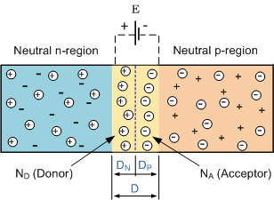
p-n Junction
At depletion zone, e- and holes combine and annihilate, E-field generated which creates a voltage barrier across junction
Forward Bias
Reduces p-n junction’s depletion layer, allows high current flow
Reverse Bias
Increases p-n junction’s depletion layer, blocks current flow
Advantages of Semiconductor Devices
Small size, low power consumption, no warm-up time
Photovotaic Solar Cells
When excited by sunlight, e- attracted toward p-type region and holes attracted toward n-type region
Magnetic Properties
Consequence of magnetic moments from e-
Types of Magnetic Moments
e- orbits around nucleus + e- spin on axis
Relative Permeability
Measure of degree to which material can be magnetised
Diamagnetism
Weak form of magnetism that only persists when external field is applied
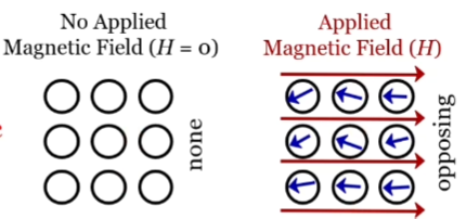
Diamagnetic Properties
Induced by change in orbital motion, with extremely small magnitude and direction opposite to applied field
Paramagnetism
Each atom possesses a permanent dipole moment by incomplete cancellation of e- spin and/or orbital magnetic moments
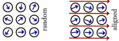
Paramagnetism Properties
No net magnetism without external magnetic field. With external field, dipoles free to rotate indiviudally - dipoles align in external field
Ferromagnetism
Permament magnetic moments result from atomic magnetic moments due to: e- spin, orbital magnetic moments, and coupling interactions
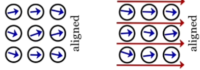
Ferromagnetism Properties
Displayed by transition meetals, magnetic susceptibilities reach up to 10^6
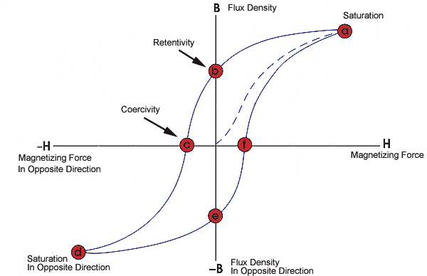
Hysteresis loop
Indicates magnetic energy loss per volume (converts to heat, increases temp)
Large Hysteresis Loop
Hard magnet, energy loss larger
Small Hysteresis Loop
Soft magnetic, energy loss smaller
Hard Magnet
Once magnetised, stay magnetic for a long time and cannot easily have their directions switched
Soft Magnet
Easy to magnetise and demagnetise, and lose little energy when switching directions
Increasing Temperature of Magnet
Increases thermal vibration of atoms, leads to dipole misalignment (decrease in saturation magnetisation)
Max Saturation of Magnet
0 Kelvin
Curie Temperature
Transition temperature where certain materials lose their permanent magnetic properties
Heat
Transfer of thermal energy due to a difference in temperature
Thermal Conductivity
Heat transferred from high- to low-temp regions
Direction of Flux
Perpendicular to heat flow direction
Heat Flux
Thermal conductivity x termperature gradient
Phonons
Lattice vibrations, through which heat is transported
Means of Heat Transport
Phonons and movement of free electrons
Vibrational Heat Capacity
Consists of elastic waves with range of distributions/frequencies
Effect of Alloying
Decreases conductivity (impurities slow electron motion)
Light
Electromagnetic radiation consisting of waves made of photons
Forms of EM Radiation
Light, heat, radar, laser, microwave, radio wave, infrared, x-ray
Radiation (light intensity)
Energy being trasmitted per unit time across unit area perpendicular to direction of propagation
400-800nm
Visible light wavelength
White Light
Mixture of all colours (wavelengths)
Light Transmission
Light completely passes through object (transparent object)
Light Absorption
Atoms absorb photons as energy
Electronic Polarisation
Caused by E-field component interacting with electron cloud (some energy absorbed)
Emission of Photon
Stimulated electron cannot remain excited, decays to ground state
Transparent
Little/no aborption or reflection
Translucent
Light transmitted diffusely, scattered within interior
Opaque
All light absorbed or reflected
Electrically Insulating Materials (Polymers/ceramics)
Can be made transparent or opaque
Can be opaque or transparent
Semiconductors
Intrinsically Transparent
Made transparent/opaque because of interor reflection and refraction
Sources of Internal Scattering
Grains boundaries in polycrystalline materials, two-phases in materials, internal pores
Polymer Translucency
Influenced by the extent of crystallinity, some scattering occurs between boundary of crystalline and amorphous regions
Highly Crystalline Polymers
Translucent or opaque due to high degree of scattering
Highly Amorphous Polymers
Completely transparent due to low degree of scattering
Refraction
Change in direction of a wave due to change in its speed (passing from one medium to another)
Refractive Index, n
The ratio comparing the speed of light in a vacuum to the speed of light in a specific material
Bends towards normal
Light enters medium with higher refractive index
Bends away from normal
Light enters medium with lower refractive index
Snell’s Law
The formula used to find the angle of refraction of light
Velocity of Light in a Medium
A function of electric permittivity and magnetic permeability of the medium
Isotropic Refractive Index
Independent of crystallographic direction (for ceramics w/ cubic crystal structures and glasses)
Anisotropic Refractive Index
Dependent on crystallographic direction (for non-cubic crystals)
Direction with highest density of ions
Highest refractive index for an anisotropic crystal
Reflection
When light radiation passes from one medium to another with different n, some light is reflected at interface of media
Reflectivity (R)
Intensity ratio between reflected and incident beams (how much light gets reflected)
Absorption Coefficient
A materials tendency to absorb light, large coefficient = more absorption
No absorption and transparent
Material with a band gap energy more than 3.1eV - band gap energy too great to absorb any photons
Full absorption and opaque
Material with a band gap energy less than 1.8eV - band gap small enough so all photons are absorbed
Partial absorption and coloured
Material with a band gap energy between 1.8 and 3.1eV - some wavelengths are absorbed
Colourless
Effect of uniform absorption for all visible wavelengths
Colour of Material
The result of the combination of wavelengths that are transmitted AND re-emitted (after absorption)
Optical Fibres
Transmits signals photonically through opitcally transparents fibres
Benefits of Fibre optics
Improved transmission speed, density & information density, reduction in error rate, with no electromagnetic interference
Components of Optical Fibre
Core, cladding, coating
Core
Innermost part of optical fibre where light signal passes through, made of high-purity silica glass
Cladding
Middle layer of optical fibre that constrains light rays within core
Coating
Outer layer of optical fibre that protects internal components from damage
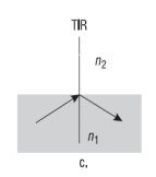
Total Internal Reflection
Effect that occurs when angle of incidence exceeds the critical angle (very shallow angle), 100% of light reflects back into core