higher graphics
1/82
There's no tags or description
Looks like no tags are added yet.
Name | Mastery | Learn | Test | Matching | Spaced | Call with Kai |
|---|
No analytics yet
Send a link to your students to track their progress
83 Terms
Extrude
The term used when a 2D profile is pulled into a 3D shape. The term add or subtract must be used to describe the function of the extrude.
Revolve
A profile that is rotated around an axis.
Subtract
Used in conjunction with features to describe material being removed from a 3D model.
Assembly
Multiple components combined to create a model.
Fillet
A rounded edge applied to a corner. Can be applied in either the sketch or as a stand-alone feature.
Chamfer
A straight edge applied to a corner. Can be applied in either the sketch or as a stand-alone feature.
Shell
Used to remove material from the inside of a 3D model. It can also be used to remove a face.
Materials
Apply a material to a CAD model. This can be used for illustration or to conduct a CAD simulation or test.
Align
To align the face of a 3D model with another face.
Centre Axis
To find the centres of cylindrical 3D CAD models and align them.
Component
A single component part, used to create an assembly later on.
Mate
To join the face of a 3D model to another face.
Cad Library
A directory of commonly used parts.
Sketch
The name given to the CAD drawing feature used to create a profile.
Axis
An axis represents a line traveling in a direction. Typically, these are X, Y, and Z but can be combinations.
Datum
A key point in which dimensions, sizes, and other details are taken from.
Sub-assembly
An assembly of components that is added to another, larger assembly.
Suppress
To turn a feature or command off within the modeling tree.
Solid Model
An object that can be viewed from any angle, geometry created within 3D space.
Wire Frame
A method of presenting a 3D CAD model, showing only the edges. Faces are transparent.
Modelling Tree
The linear hierarchy of how a 3D CAD model is created or assembled.
Sited Environment
An environment that represents how the 3D CAD model would look in a realistic environment.
Top down modeling
Top down design is an option to create new parts within assembly. Constraints are the existing geometry elements from other parts within assembly:lines, planes, surfaces, points, vertices.
Bottom up modeling
Bottom up modeling is when parts are modeled then inserted and fixed in relation to other components in an assembly using mates.
Reflection
A reflection in material, color, or light on the 3D CAD model or in the scene.
Light source
The source of light to illuminate a 3D CAD model and scene.
Intersect
Two 3D CAD features that pass through one another, with the result that only the area that the two touch remains. Everything else is deleted.
Extrude along a path
A profile that has been extruded by following a set route or ‘path’.
Helix
A profile that revolves around an axis but has an offset or pitch distance. Often used to model threads, screws, or springs.
Irregular chamfer
The removal of an edge by a cut, where the distance changes along the length of the edge.
Box array
An item repeated in a square or rectangle, with regular spacing.
Linear array
An item repeated along an edge, with regular spacing.
Irregular fillet
A rounding of an edge, where the radius will change.
Loft
A command where two or more profiles on workplanes that are spaced apart are joined to create a 3D feature.
Faces
A command where two or more profiles on workplanes that are spaced apart are joined to create a 3D feature.
Edge
The edges of a 3D object.
Vertices
The ‘corners’ or where edges meet on a 3D object.
Fixed
To hold a 3D CAD model in a fixed point, without applying any constraints. Usually applied to the first component in an assembly.
Projected edge
To select an edge from a CAD model or feature and generate it as a new line in a sketch.
Array
A method of repeating a shape along a line, in a box, or around a circle.
Work plane
A surface where sketches can be applied. Most CAD packages will provide three (elevation, end elevation, and plan), but more can be added by the user.
Radial array
An item repeated in a circle with regular spacing.
Profile
The name given to a 2
bathtub
blockwork

brickwork

concrete

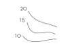
contour
door

drainage

existing tree - to be removed

existing tree

fixed window

insulated board

lamp

north sign

pivot centre window

proposed tree

radiator

sawn timber

shower tray

sinktop

sink

socket

switch

towel rail

wash basin

wc

window - hinged at bottom

window - hinged at side

window - hinged at top

window - sliding horizontally

DTP Raster
use pixels to display photos / images. The more pixels the better the quality for zooming in, but poor quality of low resolution
Jpeg
a type of DTP Raster. Used to be the most common image format as low file size, by now superseded by PNG
Bmp
a type of DTP Raster. Huge image files as they retain all their information but can’t be compressed or used in transparencies
Png
a type of DTP Raster. The best image format for digital photo use on websites etc, as files are small, sharp and clear, good for transparencies
Tiff
a type of DTP Raster. Most commonly used in graphic design as it can store high quality images and can be compressed. Best for photos that can be used in books and packaging instead of just digitally.
DTP Vectors
used for designing graphics such as cartoons / CAD models and scale up and down with no loss in quality as uses mathematical vector program. Not photos
Svg
a type of DTP vector. can be created in 2D and enlarged without losing any quality, but is a small file size. Isn’t good for using in transparency
Dxf
a type of DTP vector. Used for file to work across CAD and vector packages so you can create a drawing in either package and transfer it over for further work
3ds
a type of CAD vector. stores information on the makeup of 3D vector graphics and includes material finishes, lighting styles, which make it good for animation
Step
a type of CAD vector. Intended for creating, editing and sharing 3D Cad models across various CAD programs. Standardised file format, makes sharing easier
Iges
a type of CAD vector. Smaller than Step files and more suited to surface modelling CAD files. Designed to transfer 2D and 3D data between CAD systems.