CHAPTER 14: Weight and Balance
1/50
There's no tags or description
Looks like no tags are added yet.
Name | Mastery | Learn | Test | Matching | Spaced | Call with Kai |
|---|
No analytics yet
Send a link to your students to track their progress
51 Terms
Weight and Balance Importance
Critical factors affecting Safety, Performance, Efficiency of any A/C
Proper Loading Benefits
Ensures A/C performs within its Limits (Structural Aerodynamic),
handles Predictably
achieves Optimal Fuel Consumption.
Improper Loading Consequences
Can result in
Reduced Performance
Control Difficulties
Loss of Stability
during critical phases such as T/O or Landing.
Jet Aircraft vs. Small Aircraft W&B
Jets require Precise Calculations based on defined Weight Categories & Reference Points.
Small aircraft W&B is often estimated Visually.
Pilot Operational Responsibility
Pilots remain solely responsible for the overall safety of the flight even if they are not directly involved in the physical loading process.
Standardized Definitions Purpose
prevent miscalculations affecting stability by Ensuring
Accurate Load Distribution
compliance with operational limits

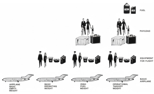
Basic Empty Weight (BEW)
Weight of A/C, including all
Fixed Equipment
Unusable Fuel
Full Operating Fluids (engine-oil, hydraulic-fluid, etc.).
Formula:
BEW = Empty A/C + Unusable Fuel + Operating Fluids
Unusable Fuel
Remains after fuel Run-Out test as per regulations
Divided into two parts:
Drainable: removed by Sump Drains
Trapped: Cannot be removed
Not considered usable for flight operations
Usable Fuel
Amount of total fuel available for engine use during flight.
Usable Fuel = Total Fuel - Unusable Fuel
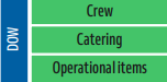
Dry Operating Weight (DOW)
Total weight of A/C ready for operation, Including:
Crew
Catering
Potable Water
Special Equipment
Excluding:
Usable fuel
Traffic-Load
Formula:
DOW = BEW + Crew + Operational Items
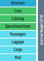
Zero Fuel Weight (ZFW)
Weight of A/C + Payload Without Usable Fuel.
It Must never exceed the Max. Zero Fuel Weight
Formula:
ZFW = DOW + Payload (Passengers + Baggage + Cargo)

Payload
Total weight of Revenue load, including;
PAX, cargo or mail.
Formula:
(Payload = ZFW – DOW)

Useful Load
Consists of:
Payload
Usable Fuel
Engine-Injection fluid.
Formula:
Useful Load = MTOW - BEW
Ramp/Taxi Weight
Total weight of A/C @ Ramp, including fuel, passengers, and cargo
Before Engine Start
Formula:
Ramp/Taxi weight = ZFW + Usable Fuel
Takeoff Weight (TOW)
Weight of the equipped, loaded, and fueled A/C @ T/O
TOW = Ramp - Taxi Fuel
Landing Weight (LW)
A/C Weight at TD (Touch-Down)
Formula:
LW = TOW - Trip Fuel Burned
Gross Weight (GW)
Total weight of A/C after All items have been Added.
Maximum Zero Fuel Weight (MZFW)
Maximum Permissible weight of A/C Without→Usable fuel.
Formula:
AZFW ≤ MZFW
Maximum Takeoff Weight (MTOW)
Max. Permissible structural (by design) total A/C weight for T/O Formula:
TOW ≤ MTOW
Maximum Landing Weight (MLW)
Maximum permissible structural (by design) total A/C weight at TD.
Formula:
LW ≤ MLW
Maximum Ramp/Taxi Weight (MTW)
Max. Allowable weight Authorized for Taxi-Operations prior to takeoff; it includes Taxi & Run-Up fuel.
Formula:
Max. Ramp/Taxi weight ≤ MTW
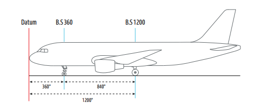
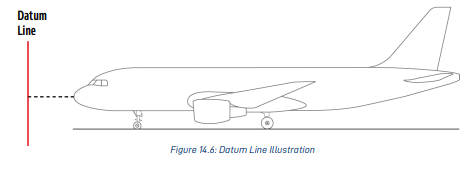
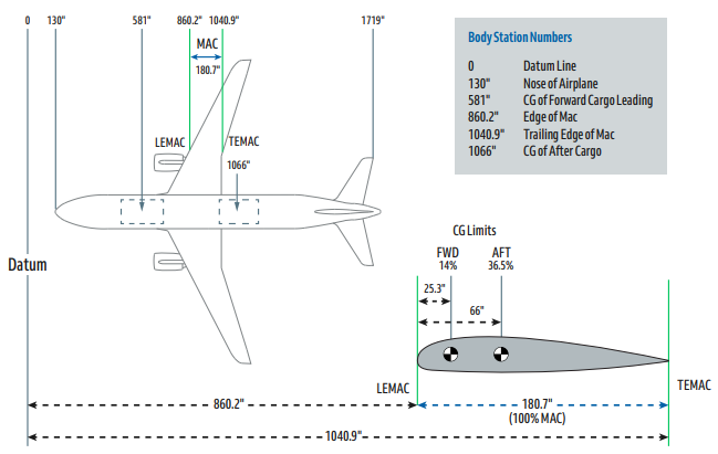
Datum Line
Imaginary Reference Vertical plane line,
Established by Manufacturer,
from which all Horizontal Distances for balance Calculations are Measured.

Body Station Numbers
Reference points along Length of A/C
Measured in Inches or Millimeters
from Datum-line to locate: Components & Weight items.
usually Located near or ahead ofA/Cs nose as shown.
Arm (Moment Arm)
Horizontal distance from Datum-Line to→CG of an item
Moment
Measurement of Tendency to produce Rotation
about a point or axis.
Formula:
Moment = Weight × Arm
Center of Gravity (CG)
Specific point where Total weight of A/C
is evenly Balanced in all Directions.
Empty Weight Center of Gravity (EWCG)
Center of gravity of A/C in its basic empty weight condition.
CG Position Stability
An object has only One CG, Position remains Constant
Unless there is Change in:
Physical Characteristics
Load Distribution.
Airplane CG Limits
CG must stay within prescribed limits to maintain A/C
Aerodynamic Stability.
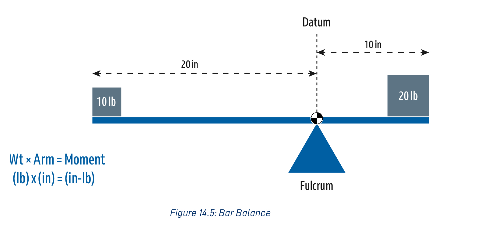
Bar Balance Calculation Example
A 10-pound weight with a 20-inch arm creates a moment of 200 pound-inches, balancing a 20-pound weight with a 10-inch arm (200 pound-inches).
Moment Measurement Unit
Measured in Pound.Inches
Airplane Weight and Balance Consistency
as A/C’s CG shifts with every loading,
Fixed datum line is Established
as an Arbitrary Reference for All Calculations.
Datum Line Placement
Positioned @ or Ahead of Nose in most modern transport aircraft
to ensure all moments are +Positive and prevent negative values.
CG Determination Principle
Calculated by finding the point where: sum of all moments
Relative to Datum is balanced by Total weight.
Formula:
CG = Total Moment ÷ Total Weight
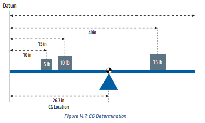
CG Calculation Example Numbers
Weights of 5 lb at 10 in, 10 lb at 15 in, and 15 lb at 40 in result in a CG location of 26.7 in from the datum.

Mean Aerodynamic Chord (MAC)
Chord length of an imaginary airfoil section producing;
Same Aerodynamic Force Characteristics as Actual Wing.
MAC Usage
Define Relative Locations of:
Wing’s CP
A/C’s CG
Leading Edge Mean Aerodynamic Chord (LEMAC)
Distance in inches from
Datum-Line to Leading Edge

Trailing Edge Mean Aerodynamic Chord (TEMAC)
Distance in inches from
Datum-Line to Trailing Edge
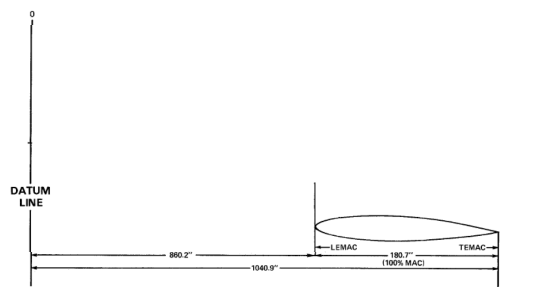
MAC Length (100% MAC)
Difference between LEMAC & TEMAC Positions.
MAC Example Values
LEMAC = 860.2 inches.
TEMAC = 1040.9 inches.
MAC length (100% MAC) = 180.7 inches.
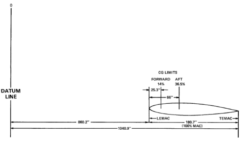
CG Limit Expression
Forward & Aft CG limits are expressed as % Percentages of MAC,
Measured from LEMAC.
%MAC Calculation Formula
%MAC = (Distance from LEMAC ÷ MAC Length) × 100
%MAC Calculation Example 1
If the forward limit is 25.3 inches from LEMAC and MAC is 180.7 inches:
(25.3 ÷ 180.7) = 14% MAC.

%MAC Calculation Example 2
If the forward limit is 45 inches from LEMAC and MAC is 180.7 inches:
(45 ÷ 180.7) = 25% MAC.
Load Index
Figure representing a CG position used for calculations in:
Manual or Computerized Load
Trim Sheets.
Dry Operating Index (DOI)
Figure representing a CG position of Dry Operating Weight, unique for each A/C’s:
Tail Number
Cabin Configuration.
Load Index Zero Fuel Weight (LIZFW)
Calculated by distributing passenger and cargo load
Load Index Takeoff Weight (LITOW)
Determined by adding
Fuel weight index correction to LIZFW
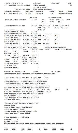
Manual Load Sheet
Hand-prepared document using
Standard Charts
Arm Values;
This method ensures safe loading but it is;
Time-Consuming
High likelihood of Human-Error.
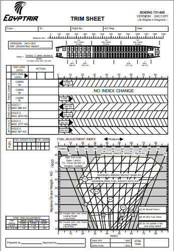
Computerized Load Sheet
Generated using Software, instantly Calculates;
ZFW, TOW, LW, and CG with;
High-Accuracy
Allows for last-minute load changes (LMC)