physics oral
1/14
There's no tags or description
Looks like no tags are added yet.
Name | Mastery | Learn | Test | Matching | Spaced | Call with Kai |
|---|
No analytics yet
Send a link to your students to track their progress
15 Terms
Electric charge and electric field
Explain the concept of electric charge and the definition of the electric field, and discuss how electric interactions are described by field quantities.
Electric charge is a property of matter causing electric interaction.
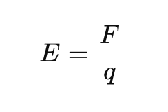
Electric field is force per unit charge:
Electric interactions are described using electric fields. Charges create electric fields, fields exist in space. F = qE (force acting on electric charge)
Coulomb’s law
Explain Coulomb’s law, including the physical meaning of the quantities involved, and discuss the nature of electrostatic interaction between charges.
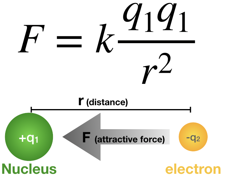
Force between stationary charges. States that the magnitude of the electric force is directly proportional to the product of the magnitude of the charges, and is inversely proportional to the square of distance between them.
F = electrostatic force
k = coulomb’s constant
q1 q2 = electric charges
r = distance
Opposites attract.
Likes repel.
Force acts on staight line connecting the two charges.
Electric potential and voltage
Explain the concepts of electric potential and electric potential difference, and discuss their physical interpretation in electrostatics.
Electric potential is the potential energy per unit charge.
V = U/q (V = electric potential (volts), U = electric potential energy (joules), q = electric charge (coulombs))
Electric potential difference, aka voltage, represents the work done per unit charge.
△V = W/q (△V = voltage, W = work done, q = charge)
In electrostatics, electric fields create differences in electric potential.
Electrostatic field – conservative nature
Explain the conservative nature of the electrostatic field and discuss its consequences for work, potential, and voltage.
Electrostatic field is conservative. The work done by electric force only depends on the start and end points. Work is independent of path taken.
The same amount of work is required for moving a charge between two points regardless of path taken. Total work done around closed loop is zero.
Conservative fields allow potential energy to be defined. Work is related to potential energy.
W = -△U (W = work done, U = change in electric potential energy)
Electric potential is the potential energy per unit charge.
V = U/q
Exists because field is conservative.
Voltage is potential difference between two points.
△V = W/q
Because the field is conservative, voltage only depends on two points & is independent of the path taken between them.
Gauss’s law
Explain Gauss’s law, including the concept of electric flux, and discuss how symmetry can be used to determine electric fields.
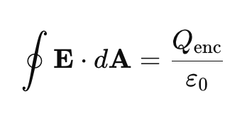
Gauss’s law states that the total electric flux through a closed surface is proportional to the enclosed charge.
E = electric field
dA = surface area vector
Q_enc = total enclosed charge
E_0 = permittivity of free space
Electric flux measures the amount of electric field that passes through a surface.
Φ=∮E⋅dA
Φ - electric flux
E = electric field strength
dA = surface area
Symmetry allows us to choose Gaussian surface to calculate the electric field easier. We match the surface to the charge distribution
spherical
cylindrical
planar
Dielectrics and displacement field
Explain the role of dielectric materials in electrostatics, including permittivity, polarization, and the meaning of the electric displacement field.
Dielectric is an insulating material that does not allow free movement of electric charge but responds to external electric field. Becomes polarized in an electric field.
Permittivity is the ability of a material to permit the formation of an electric field.
ϵ = ϵrϵ₀
Polarization is when an electric field is applied. Positive and negative charges are slightly displaced and electric dipoles align. It produces an internal electric field that opposes external field.
Displacement field includes free charges and polarization effects. Defined as D=εE.
Capacitors
Explain the operating principle of capacitors, including the definition of capacitance, energy storage, and basic capacitor types.
Capacitor is a device that stores electric charge & electrical energy. It consists of two conducting plates & is separated by a dielectric.
Capacitance is the ability of the capacitor to store charge.
Defined as:
C=Q/V
C = capacitance
Q = stored charge
V = voltage
Capacitor stores energy in the electric field.
W=1/2 CV²
Operating principle is based on charge separation.
charge accumulates on the plates
electric field develops between them
electrical energy is stored in the field
Basic capacitor types:
parallel-plate capacitor
ceramic capacitor
film capacitor
electrolytic capacitor
Electric current
Explain the concept of electric current and discuss charge transport in conductors using macroscopic and microscopic descriptions.
Electric current is the ordered movement of electric charges. It describes the rate of charge flow through a conductor.
I = △Q/△t
I = electric current
△Q = amount of charge passing through cross-section
△t = time interval
Direction of current is the direction at which positive charges would move.
Macroscopic description treats current on observable quantities: charge, voltage, resistance.
Microscopic description explains current as the motion of charge carriers, typically electrons in conductors.
Effects of electric current
Explain the physical effects of electric current, including thermal, magnetic, and chemical effects, and discuss their practical importance.
Electric current has thermal, magnetic, and chemical effects. Thermal effect is caused when electrical energy is converted into heat (aka Joule heating). P = UI or P = I² R. Practical applications include electric stoves and kettles.
P = power
U = voltage
I = current
R = resistance
Magnetic effect happens when an electric current creates a magnetic field around the conductor. Allows electrical energy to be converted into mechanical energy & vice versa. It is used in electromagnets, transformers, generators.
Chemical effect is caused when chemical reactions occur because of electrolysis - when current passes through an electrolyte. Practical applications: electroplating, battery charging, production of chemicals.
DC circuits and source models
Explain the basic principles of direct current (DC) circuits, including ideal and real voltage source models, internal resistance, and the behavior of series and parallel resistor networks. Discuss the concepts of voltage and current division.
Direct current (DC) circuits is an electrical circuit where current flow in one constant direction. Basic quantities are voltage (V), current (I), resistance (R). Relationship is defined by ohm’s law: V = IR.
Ideal voltage source has a constant voltage regardless of current drawn. No internal resistance. Real voltage has internal resistance, which causes voltage to drop when current flows.
Series resistor has the same current. Resistances add up.
Parallel resistors has the same voltage. Current divides among the branches.
Voltage division is used in series networks. Voltage across each resistor is proportional to its resistance.
V1 = V(R1/R1 + R2)
Current division is used in parallel networks. Current divides inversely proportional to resistance.
I1 = I(R2/R1 + R2)
Resistance and Ohm’s law
Explain the concept of electrical resistance and resistivity, state Ohm’s law, and discuss electrical power dissipation in conductors.
Electrical resistance opposes the current flow. Resistivity is the intrinsic property of a material.
resistance of conductor:
R = p L/A
Ohm’s law states that the current through a conductor is directly proportional to the applied voltage and inversely proportional to the resistance.
When current flows through a resistor, electrical energy is converted into heat (Joule heating). Electrical power is dissipated as: P = UI
using ohm’s law:
P = I²R and P = U²/R
Kirchhoff’s laws
Explain Kirchhoff’s current and voltage laws and discuss their physical background in terms of charge and energy conservation.
Kirchhoff’s current law (KCL) states that the sum of the current entering a junction is equal to the sum of a current leaving a junction. ΣI = 0. KCL is a consequence of the conservation of electrical charge, meaning charge cannot accumulate at a junction.
Kirchhoff’s voltage law states that the sum of all voltage changes around any closed loop is zero. ΣU = 0. It is based on conservation of energy, meaning that energy gained from voltage sources is equal to energy consumed by circuit elements.
Magnetic field and magnetic forces
Explain how electric currents produce magnetic fields and how magnetic forces act on charges and current-carrying conductors.
When an electric current flows through a conductor, a magnetic field is generated around the conductor. The direction of the magnetic field can be determined by the right-hand rule. Point thumb to direction of conventional current and curled fingers show direction of magnetic field lines.
Magnetic field acts on a moving charge. Given by F = qvBsinθ.
F = magnetic force
q = electic charge
v = speed of moving charge
B = magnetic field strength
θ = angle between velocity vector v and angle B
Current-carrying conductors experience magnetic force in magnetic field because current consists of moving charge. Force on straight conductor is F = BIL sin θ.
F = magnetic force
B = magnetic field strength
I = current
L = length of conductor
θ = angle between direction of current and magnetic field
Electromagnetic induction
Explain electromagnetic induction, including Faraday’s law and Lenz’s law, and discuss their significance in engineering applications.
Electromagnetic induction is when a changing magnetic field creates an electromotive force (EMF).
Faraday’s law states that an EMF is induced whenever the magnetic flux through a circuit changes. ε= - dΦ_B / dt
Lenz’s law states that the induced current always flows in a direction that opposes the change in magnetic flux that produced it.
Engineering applications include electric generators, transformers, wireless charging.
Field–circuit connection
Discuss how field concepts (electric field, potential) are related to circuit quantities (voltage, current), and explain under what assumptions circuit models can be used.
Electric field exerts force on electric charge and causes them to move. Electric field is related to electric potential by E = -▽V. Electric field is the field quantity, voltage is the corresponding circuit quantity. Voltage is the driving force that causes charges to move.
Electric field causes charge motion, and charge motion appears as current in circuit theory. J=σE.
Circuit models can be used under the assumption that the system is lumped, meaning physical dimensions are small compared to the wavelength, and fields can be considered uniform within components.