PHYS C9
1/49
There's no tags or description
Looks like no tags are added yet.
Name | Mastery | Learn | Test | Matching | Spaced | Call with Kai | Chat |
|---|
No analytics yet
Send a link to your students to track their progress
50 Terms
Radiologists
doctors who help make a diagnosis from a medical image and use interventional radiology to guide minimally invasive procedures and/or provide treatment
Radiographers
use x-rays and MRI to produce images of internal body structures
Fluoroscopy
real-time, continuous x-ray image allows visualisation of organ movement
radiographer operates imaging equipment while a specialist performs invasive part of procedure
Radiography Imaging Systems
different shapes and sizes
25 to 150 kVp
10 to 1200 mA
Radiography Imaging Systems Components
X-ray generator
Coolidge x-ray tube (cathode/anode)
Digital detector that captures non-attenuated radiation
Modern Radiography Imaging System Examples
Digital Radiography (DR)
Computed Radiography (CR) - older
Portable/Mobile Units
Dental
Mammography
Fluoroscopy
Computed Tomography (CT) and Cone Beam Computed Tomography (CBCT)
Medical Imaging:
MRI
PET/SPECT
Ultrasound
Supporting the Imaging System
X-ray tubes can be suspended from ceiling or on a stand attached to floor
detector (bucky) beneath table or behind bucky stand (chest x-rays)
Portable C-arms rotate freely around patient without being attached to table in surgical or interventional settings (e.g. fluoroscopy)
Tables floating, easily unlocked, and are moved manually or via motor
Operating Console
Anatomically Programmed Radiography (APR)
Automatic Exposure Control (AEC)
Safety features: two stage exposure switches, emergency stop buttons, and indicators for tube status and radiation emission
Integrated displays show thumbnail images and allow image annotation
Anatomically Programmed Radiography (APR)
pre-set protocols (e.g. Spine Cervical AP/Lateral) load recommended factors (kVp, mA, time) but can be modified by radiographers via touchscreen controls
Automatic Exposure Control (AEC)
detectors measure radiation reaching the receptor and terminates exposure time (mAs) once appropriate dose is receive
DAP vs AEC
DAP (Dose Area Product): ionisation chamber mounted on collimator, indicates radiation dose
AEC: ionisation chamber positioned after patient, before image receptor, indicates image quality
keV Radiation Therapy
Low energy radiation used when cancer is close to/on skin surface
E.g nasal cavity tumours
Superficial RT: 50 - 200 keV used to treat cancer up to 5mm from skin surface
Orthovoltage RT: 200-500 keV used to treat cancer 4-6cm deep
X-ray Generator Circuit
autotransformer adjusts input mains voltage
step-up transformer increases voltage
Rectifier converts high voltage AC to DC
step-down transformer reduces voltage to tube filament
Autotransformer
portions of the same winding act as both the primary and secondary coils, rather than being separate with no conducting connective path
Autotransformer Self-Inductance
AC current flows through coil, producing a changing magnetic field. This induces a voltage along same coil
Depends on number of turns (higher = more) and material conductivity
Bottom = low V
Top = high V
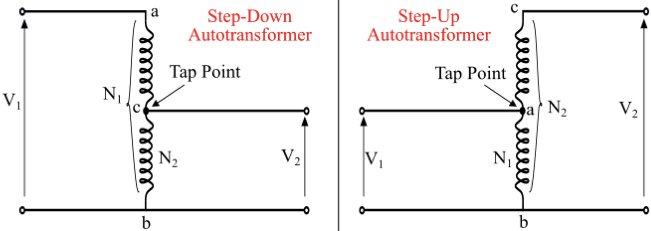
Autotransformer Tap point
movable or fixed connection that controls the output voltage
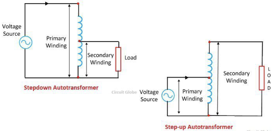
Step-Up vs Step-Down Autotransformer
Step-Down:
N2 < N1
V2 < V1
V1 applied across entire winding, output taken from a potion of it
Step-Up:
N2 > N1
V2 > V1
V1 applied across portion of winding, output taken across full winding
Autotransformers in an X-ray Circuit
One autotransformer simultaneously serves 3 functions:
power supply for the high-voltage (kV) circuit that selects tube kVp
power supply for the filament (mA) circuit, which uses tap points to control filament temp, thus tube current
Compensates for incoming mains voltage fluctuations
Autotransformer’s kVp selector
varies kVp to tube by controlling input to step-up transformer
major (increments of 10) or minor (increments of 1)
Mutual Induction
effect of one coil's magnetic field on another coil's magnetic field
Magnetic field produced by circuit 1 induces a current in circuit 2. This induced current has its own magentic field that interacts with the magnetic field of circuit 1
dependent on geometrical arrangement - the closer the two circuits, the larger the magnetic flux through circuit 2 (larger mutual induction)
X-ray Generator Circuit Sections/Sub-Circuits
Low-voltage circuit
Filament circuit
High-voltage circuit
Low-voltage circuit
Power supply (Mains AC)
Main switch - ensures mains voltage ts within 5% either way of expected voltage
Autotransformer
Autotransformer’s kVp selector
Exposure switch - closes circuit so current flows to primary side of step-up transformer
Primary side of Step-up transformer
Filament circuit
Autotransformer
mA selector (sets filament amperage, controlling filament heat and number of electrons at filament - thus tube current)
Step-down transformer
X-ray tube filament
High-Voltage Circuit
Current only flows during exposure
Danegrous because of high voltage so cables are thick to meet insulation requirements
Secondary side of step-up transformer (minimum ratio 500:1)
X-ray tube
High-Frequency Generator (rectifier)
High-Frequency Generator
Rectifier unit (diode) - changes AC to DC so current only flows from filament to target
DC voltage fed into inverter circuits that rapidly switches on and off to convert DC into high frequency AC (kHz to MHz)
high frequency AC boosted by Step-Up transformer
rectifier circuit converts AC into smooth, high-voltage DC
Purposes of different voltages
high frequency AC allows for smaller and lighter transformers and capacitors
smooth (low ripple), high-voltage DC improves image quality, speeds up response times, reduces patient dose and energy wasted as heat
Computed Radiography (CR)
CR plate phosphor layer traps electrons when exposed to x-rays
Reader uses laser to scan plate causing trapped electrons to release stored energy as light
PMT collects released light and converts it to electrical signal
High-intensity light washes over plate to erase latent image, enabling reuse
Computed Radiography (CR) - Pros and Cons
Pros: low inital cost, flexibility
Cons: processing time, reader, cost of replacement plates
Digital Radiography (DR): Direct Conversion
Photoconductor/semiconductor captures x‐ray energy and converts it to electron-hole pairs proportional to intensity of incident energy
Electron-hole pairs collected under high voltage to prevent recombination and lateral spreading
Resultant charge stored at local capacitor in TFT array
E.g: CdTe, CZT, Si (mammography)
Digital Radiography (DR): Indirect Conversion
scintillator’s thin needle-shaped crystals converts x‐ray energy into visible light proportional to intensity of incident energy
photodiodes convert light to proportional charge
Resultant charge stored at local capacitor in TFT array
E.g: CsI/GOS/LYSO with SiPM/Silicon PIN photodiode
DR Pros and Cons
Pros: Image acquisition speed, excellent image quality
Cons: High initial and detector replacement cost, redundancy concerns, downtime possibilities (systems stop working for a period of time)
Cons of Indirect Conversion Only: lower spatial resolution (as light lost) and increased noise
DR and CR Similarities
Use a medium to capture x-ray energy
Produce an enhanceable digital image within seconds
How to distinguish between DR and CR
CR uses cassette to house imaging plate whereas DR just uses flat panel detector
Transistor
semiconductor electronic switch
controls the flow of electricity in circuits
Thin Film Transistor (TFT) Array
Millions of individual detector elements (DELs) arranged in a grid, each controlled by a switch, storage capacitor, and active area
deposited onto a glass substrate in multiple layers
Lowest level = readout electronics, Highest level = charge collecting semiconductor/photoconductor (direct) or scintillator and photodiode (indirect)
charge collected at each storage capacitor is amplified and quantified to a digital code value for the corresponding pixel by an ADC (Analogue-to-Digital Converter)
timing of the readout (charge from DELs) is controlled, enabling high-speed image acquisition
TFT Switch
Keeps DEL "off" during exposure, allowing capacitor to collect and store the charge generated from x-ray photons or visible light
Closes to release stored charge to readout electronics row-by-row onto data lines
Capacitor
Storage device that holds the electrical charge (signal) generated by X-ray interactions within each DEL from exposure until TFT switch closes to create image
Active/Sensing Area
collects charge generated by x-ray absorption (photodiode or photoconductor)
ADC (Analogue-to-Digital Converter)
continuous analogue electrical signals, proportional to x-ray photon intensity at DELs, translated into discrete digital binary data
analogue electrical signals measured at specific, regular intervals
Specific grey level (binary number) assigned to each measurement and mapped to a pixel in image
Measurements to define receptor’s accuracy and efficiency
Fill Factor
Point Spread Function (PSF)
Modulator Transfer Function (MTF)
Detective Quantum Efficiency (DQE)
Exposure Index (EI)
Sensitivity number (S‐number)
Radiographic contrast
Fill Factor
The size of the active area compared to total area on each DEL
Higher = more efficient = fewer x-rays needed (lower pateint dose) as more x-rays contribute to signal rather than being lost
Point Spread Function (PSF)
how a single, ideal point of x-ray radiation is blurred across neighbouring pixels in final image
measures spatial resolution: narrow PSF = high spatial resolution
Larger pixels, larger focal spots, and thicker scintillators (spread light before detection) create wider PSF which reduces image sharpness
Modulator Transfer Function (MTF)
measures accuracy of detector in transferring objects’ contrast to an image at specific spatial frequencies (resolutions)
High MTF = better spatial resolution (good at maintaining sharpness)
Ranges from 0 (no structures are visible) to 1 (all structures are visible)
MTF of 0.5 means system reproduces 50% of object contrast at that spatial frequency
Detective Quantum Efficiency (DQE)
Measures how efficiently a digital receptor captures x‐rays and converts them into acceptable radiographic density
High DQE = less x-rays needed (lower patient dose) and better radiographic detail
Low DQE = increased noise
DQE of 0.4 means receptor can utilise 40% of received x‐rays
0.3 - 0.5 = acceptable/moderate performance
Exposure Index (EI)
Aka: DEI, REX, EXI
numerical value representing the radiation level incident on the image detector
used to compare systems’ sensitivities
linear estimate of detector radiation exposure, so indicates whether dose administered was appropriate
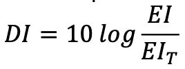
Deviation Index (DI)
compares the actual Exposure Index (EI) to the protocol Target Exposure Index (EIT) for an image
Tells radiographer how far they are from ideal exposure
0 is perfect
+1 is 25% over, +2 is 50% over…
-1 is 20% under, -2 is 40% under…
-2 to +2 usually acceptable
Radiographic Contrast
determined by number/size of pixels in a given field of view, which is directly proportional to number of DELs on TFT array
Many/small pixels = increased spatial resolution
If a DEL is dead, the ouput from surrounding DELs is averaged to form that pixel
DR - Quality Assurance Regular Tasks
Daily: warm-up, visual check
Monthly: detector calibration
Annually: full system evaluation
DR - Quality Assurance Specific Activities
tracking image rejects using software
image receptor cleaning
spatial resolution, contrast, and uniformity tests
ensure detector responses are reproducible at fixed exposures
DR - Quality Assurance Purpose
Ensure consistent image quality
Maintain detector performance over time
Support dose optimisation (avoid dose creep)
Early detection of faults and artefacts