B748 Hydraulic System
1/15
There's no tags or description
Looks like no tags are added yet.
Name | Mastery | Learn | Test | Matching | Spaced | Call with Kai |
|---|
No analytics yet
Send a link to your students to track their progress
16 Terms
What are the conditions required for the demand pump AUTO operation? FCOM 1 - 29.10.1
AUTO—
• demand pump operates when respective engine pump output pressure is low, or when respective fuel control switch is in CUTOFF
• demand pump 1 and 4 also operates when trailing edge flaps are in transit, or in flight when flaps are extended past 1
• in flight, demand pumps 2 & 3 also operate when flaps are extended past 20
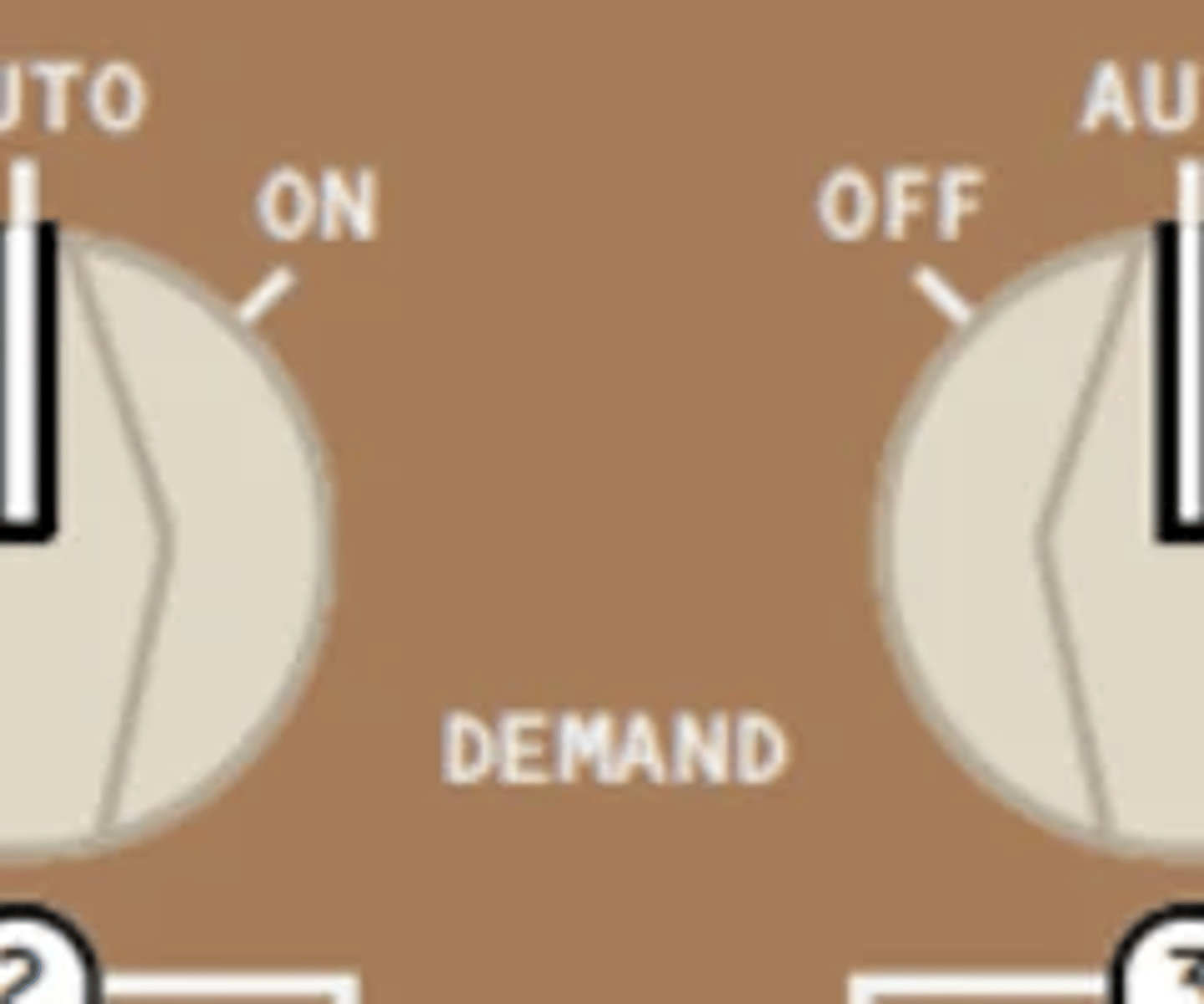
What are the conditions required for the auxiliary pump operation? FCOM 1 - 29.10.1
AUX (System 1 and 4)—
• auxiliary pump operates on the ground when the respective engine driven pump is unpressurized
• respective demand pump off

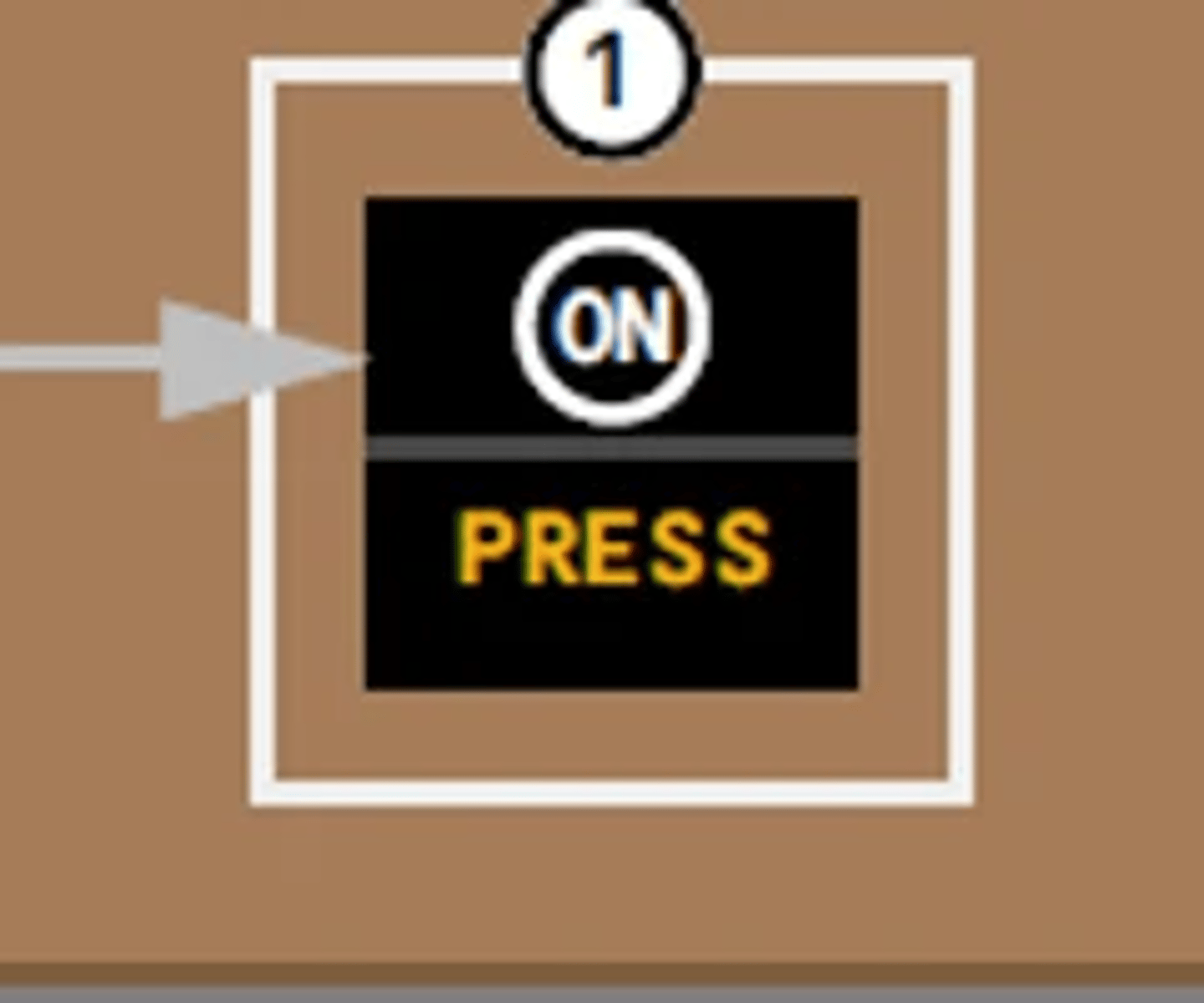
Does the demand pump press light extinguish during aux pump operation? FCOM 1 - 29.10.2
Illuminated (amber)—
• demand pump selector positioned to OFF or AUX
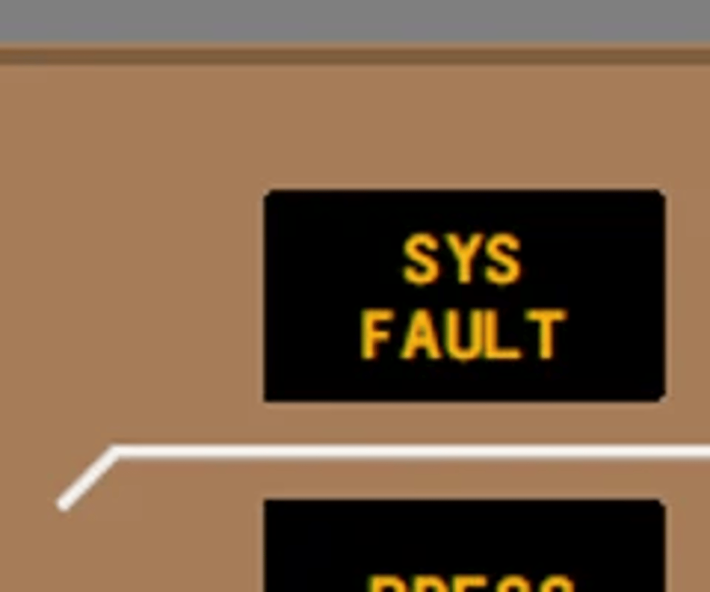
What are the reasons for hydraulic SYS FAULT light illumination? FCOM 1 - 29.10.2
Illuminated (amber)—
• low hydraulic system pressure
• low hydraulic reservoir quantity
• excessive hydraulic fluid temperature
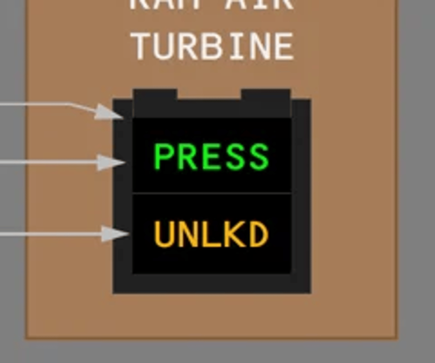
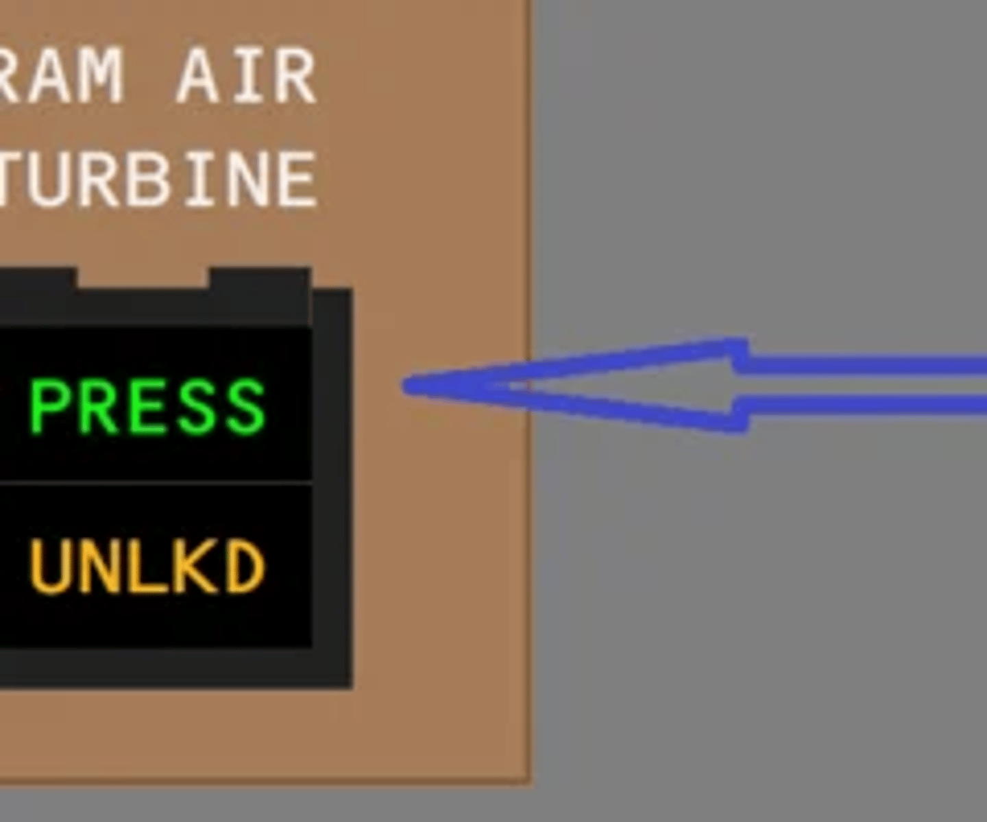
What does the green PRESS light on the RAT switch indicate? FCOM 1 - 29.10.2
Illuminated (green)—
• the RAT is operating
• system 3 primary flight control hydraulic pressure is greater than approximately 1500 psi
How can hydraulic information be presented in the MFD? FCOM 1 - 29.10.3
To view the status display, push the STAT display switch on the display select panel. To view the hydraulic synoptic, push the HYD synoptic display switch on the display select panel.
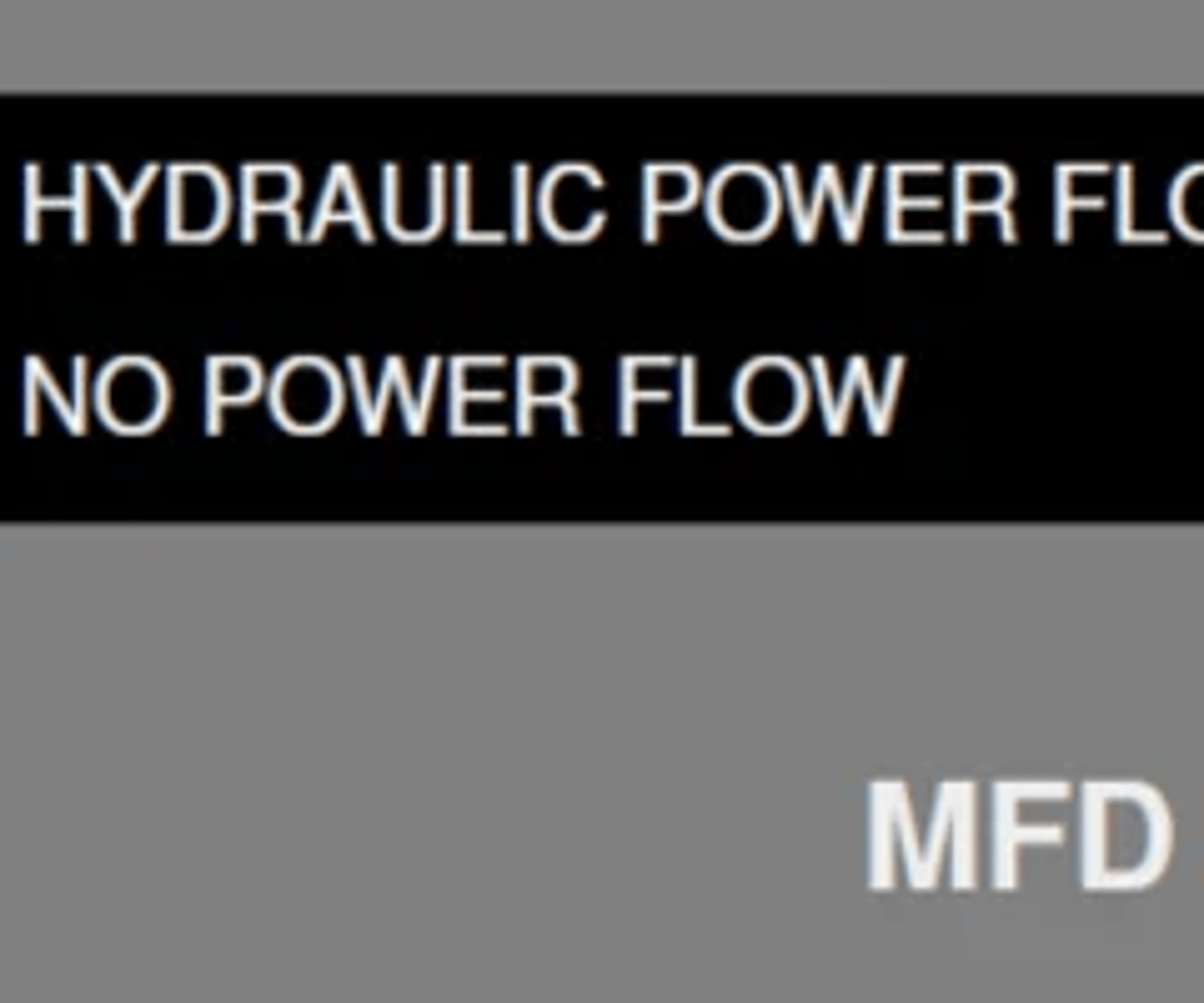
How is unpressurized system presented in the HYD synoptic page? FCOM 1 - 29.10.6
no green fill - zero
How are each hydraulic systems powered and what pumps are being used? FCOM 1 - 29.20.1
- Each system is powered by an engine driven pump and a demand pump installed in parallel.
- Systems 1 and 4 have air driven demand pumps AND systems 1 and 4 have electric auxiliary pumps for ground handling operations.
- Systems 2 and 3 have electric motor driven demand pumps.
- The ram air turbine (RAT) provides emergency hydraulic power to System 3.
When does the rat deploy automatically and what are the indications? FCOM 1 - 29.20.1
The RAT deploys manually when the Ram Air Turbine switch is pushed, or in flight when any three engines drop below 50% N2.
What pressurizes the hydraulic reservoirs? FCOM 1 - 29.20.2
The bleed air system pressurizes the reservoirs to prevent pump cavitation and ensure positive flow during high demand conditions.
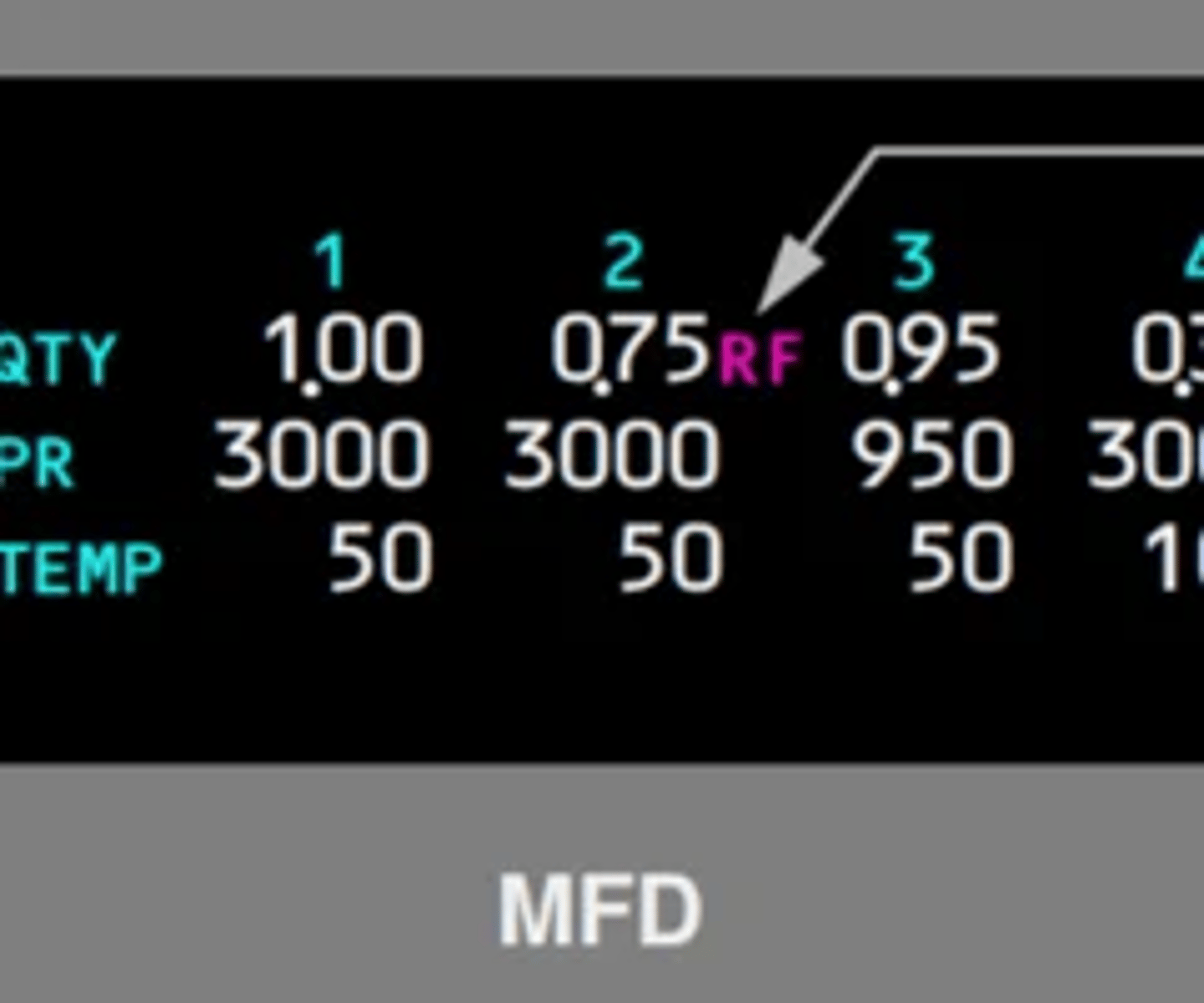
When is the ´RF´ hydraulic indication inhibited? FCOM 1 - 29.20.2
RF is inhibited in flight and replaced by the letters LO when a system low quantity exists.

What are the indications when the HYQUIM has failed and how many systems are affected? FCOM 1 - 29.20.2
Should the HYQUIM fail, the following indications
may occur for all four hydraulic systems:
• blank hydraulic quantity indications on the EICAS status page and HYD synoptic page
When does the hydraulic shutoff valve to the EDP close? FCOM 1 - 29.20.2
A hydraulic fluid shutoff valve is installed in the fluid supply line to each EDP. If an engine fire switch is pulled, the respective hydraulic fluid shutoff valve closes, the EDP depressurizes, and the respective demand pump operates.
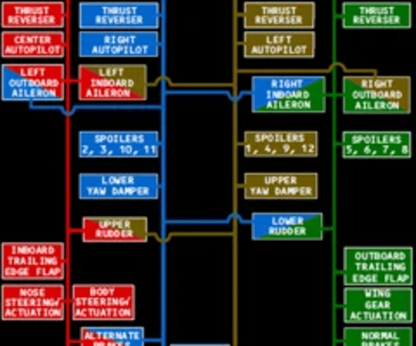
Landing gear system and trailing edge flaps are powered by which hydraulic system? FCOM 1 - 29.20.2
Systems 1 and 4 power trailing edge flaps and landing gear; and provide redundant power to primary flight controls.

What hydraulic systems are used for the L,C and R autopilot servos? FCOM 1 - 29.20.2
Systems 1, 2, and 3 power respective center, right, and left autopilot servos.
What does HYD COLD SYS X EICAS message means and what is the required action? FCOM 1 - 29.30.1
- hydraulic system is too cold for take off
- heat the hydraulic systems to 18C or higher before take off
- apply QRH procedure