Geotech Test 2
1/105
There's no tags or description
Looks like no tags are added yet.
Name | Mastery | Learn | Test | Matching | Spaced | Call with Kai |
|---|
No analytics yet
Send a link to your students to track their progress
106 Terms
What is E?
- energy used for compacting unit volume of soil
- ___ = [(# of layers)(# of blows per layer)(weight of hammer)*(height drop of hammer)]/volume of mold
As the compaction energy increases:
- the max dry unit weight increases
- the optimum moisture content decreases
Field compaction steps:
- compacted in layers of approx. 8 in (suggestion)
- surface of each compacted layer should be scarified to provide bonding between layers
- most field compaction is done with rollers
- handheld vibrating plates may be used for compaction over a small area
Types of rollers used for compaction
- smooth wheel
- pneumatic rubber-tired
- sheepsfoot
- vibratory
Field compaction requirement is specified in terms of __________
Relative Compaction
Factors affecting field compaction
- moisture content
- soil type
- number of roller passes (energy supplied)
- layer (lift) thickness
- intensity of pressure (area over which the force is applied by a given compacting equipment)
Moisture conditioning in the field for economic compaction
- contractors have freedom to choose appropriate equipment, lift thickness, # of passes, etc. to achieve the required relative compaction
- contractors ALWAYS want to achieve the required relative compaction with minimal compaction effort (cost effective)
- moisture content is an important factor for achieving the required relative density with minimum compaction effort
field compaction curve - compaction effort and moisture conditioning in the field
in the field, if there is one moisture content that can't be changed, then changing the compaction effort will help to achieve the required compaction
Smooth wheel rollers
- effective for proof rolling of subgrade and finishing (sand and clay)
- 100% coverage -> low pressure -> not good for thick layers
- 310-380 kN/m^2 contact pressure
Pneumatic rubber-tired rollers
- effective method for sand and clay
- 70-80% coverage
- 600-700 kN/m^2 contact pressure
Sheepsfoot rollers
- effective method for clayey soils
- 1400-1700 kN/m^2 contact pressure under projections
Vibratory rollers
- effective method for granular soils
- vibrators can be attached to other equipment
Methods of determining dry unit weight in the field
- sand cone method (ASTM D1556)
- drive cylinder method (ASTM D2937)
- rubber balloon method (ASTM D2167)
- water ring method (ASTM D5030)
- nuclear method (ASTM D2922)
How do we know that we have achieved the required minimum dry unit weight?
measure the dry unit weight of the compacted soil and compare
Methods of determining moisture content in the field
- standard method cannot be used in the field bc it requires 24 hr oven drying
- stir-frying
- speedy moisture tester
- microwaving
Stir-frying
- stir fry the soil sample in a drying pan over a portable stove
- fast and gives reasonably accurate results for sand and gravel
Speedy moisture tester
- add calcium carbide to the soil container known as speedy moisture tester
- calcium carbide reacts with the water in soil and produces acetylene gas
- moisture content is computed based o the acetylene pressure
Sand Cone Method
- measure the weight of the soil collected from the test hole (weight of the soil plus bucket - weight of bucket)
- fill the test hole with standard sand (Ottawa sand) and calculate the volume with known unit weight
- V(test hole) = V(soil) = V(ottawa sand) = W(ottawa)/unit weight(ottawa)
Drive Cylinder Test
- measure the weight of the excavated soil (weight of soil plus cylinder - weight of cylinder)
- volume of test hole = volume of cylinder
- faster than the sand cone method but slightly less precise
- good for silty or clay soils (enough friction to keep the sample in the cylinder)
Rubber Balloon Method
- similar to sand cone method but the volume of the excavated soil is measured using a liquid
- need to prevent liquid from seeping in the soil
- use rubber membrane (rubber balloon)
- volume of the test hole = volume of liquid used to fill the test hole
Water Ring Test
- used when soil consists of cobbles and small boulders
- use larger hole to reduce error
Nuclear method
- nuclear density meters use radioactive isotope sources
- dense soil absorbs more gamma radiation than loose soil
- the meters operate either in drilled holes or from the soil surface
- needs special training to use this equipment
Flow is due to ____________
gradient difference
Definition of Head
- an element of groundwater contains energy in various forms including: potential, strain, and kinetic energy
- this energy is expressed in terms of ______
- the energy per unit weight (mass x gravitational acceleration)
Potential energy
- due to elevation above the datum
- z
Strain energy
- due to pressure in the water
- u/γ(w)
Kinetic energy
- due to velocity of the water
- (V^2)/2g
Total head at point in water is _________
the algebraic sum of the elevation head, pressure head, and velocity head
Application for Bernoulli's equation to flow through soils
- for the flow of water through soils, the flow velocity is very small
- the velocity head can be neglected and the head is given by: h = z + u/γ(w)
Water flows only when there is a __________
total head difference (head loss or gain)/energy difference
Water always flows from a point of (a) ___________ to a point of (b) ____________
(a) high total head
(b) low total head
Pressure heads are measured using open standpipes called _______________
piezometers
Elevation head is measured from _________
a common datum
Total head difference between two points:
Δh = h(A) = h(B) = [z(A) + u(A)/γ(w)] - z(B) + u(B)/γ(w)]
Hydraulic gradient
i = Δh/L
Zone on Velocity vs Hydraulic Gradient Graph
- Zone 1: Laminar Flow Zone
- Zone 2: Transition Zone
- Zone 3: Turbulent Flow Zone
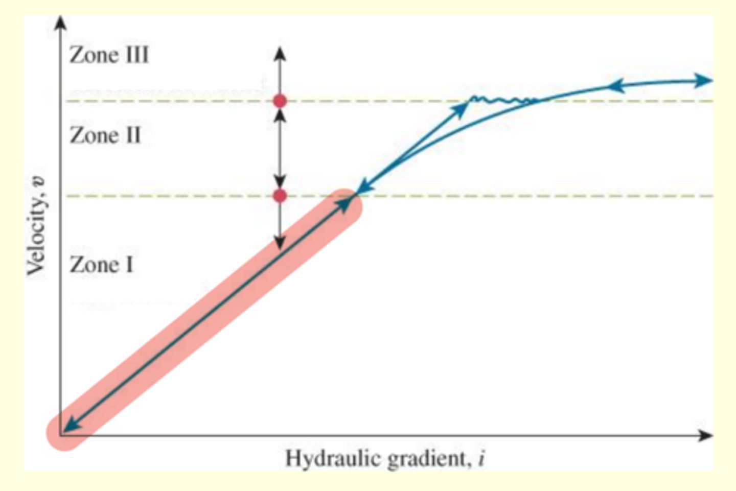
Within laminar flow (Zone 1)...
velocity is directly proportional to hydraulic gradient
Darcy's Law
- average discharge velocity (________ velocity) of water through a saturated soil is proportional to hydraulic gradient
- units of v and k are same because i is unitless
What is k?
coefficient of permeability/hydraulic conductivity
Discharge velocity
- does not account for voids
- q = vA = v (A(s) + A(v))
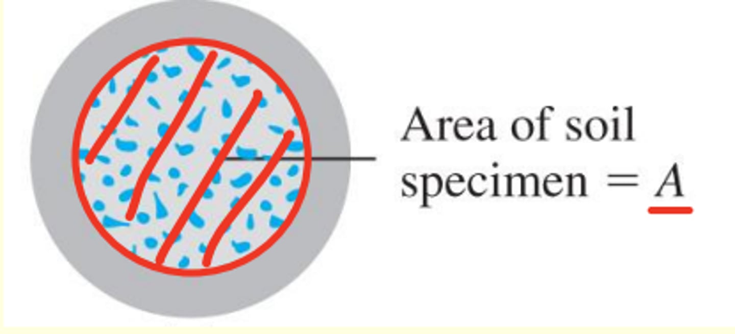
Seepage velocity
- actual velocuty
- q = v(s) * A(v)
- A(v): area of void in the cross section
Relationship between discharge and seepage velocity
V(s) = V / n
- V(s): seepage velocity
- V: discharge velocity
- n: porosity
Hydraulic conductivity depends on many factors including fluid...
- viscosity
- pore-size distribution
- grain-size distribution
- void ratio
- soil saturation
Factors that affect permeability of clays
- ionic concentration
- thickness of the layers of water held to the particles
Lab methods for determining permeability of soils (undisturbed sample)
- constant head method (used for coarse grained soils)
- falling head method (used for fine grained soils)
Empirical methods for determining permeability of soils
- granular soils: Hazen's eqn, Kozeny-Carman eqn, Chapuis eqn, and Amer & Awad eqn
- cohesive soils: Taylor eqn, and Samarasinghe et al eqn
In situ methods for determining permeability of soils (field)
- pumping tests
- constant head borehole permeameter
- boutwell permeameter
- porous probes
Measurements needed for Constant Head Method
- cross sectional area of the sample, A
- length of the sample, L
- head difference across the sample, h
- duration, t2-t1
- total volume collected, Q
Measurements needed for Falling Head Method
- cross sectional area of the pipe, a
- length of the sample, L
- cross sectional area of the sample, A
- head difference at time t1, h1
- head difference at time t2, h2
Hydraulic conductivity of most soils varies with ____________
the direction (vertical or horizontal) of the flow
What is k(V)
hydraulic conductivity in the vertical direction
What is k(H)
hydraulic conductivity in the horizontal direction
Relationship between k(V) and k(H)
k(H) is generally higher than k(V)
k(H) equivalent for flow parallel to soil layers in steady flow
- q(equiv) = q1 + q2 + q3 + ... + q(n)
- h(equiv) = h1 = h2 = h3 ... = h(n)
k(V) equivalent for flow normal to soil layers in steady flow
- q(equiv) = q1 = q2 = q3 ... = q(n)
- h(equiv) = h1 + h2 + h3 + ... + h(n)
Equation for V (velocity) given k (hydraulic conductivity) and i (hydraulic gradient)
v = k * i
Equation for Q (volume) given q (flow rate) and t (time)
Q = q*t
Equation for q (flow rate) given v (velocity) and A (area)
q = v*A
Equation for i (hydraulic gradient) given Δh (head loss) and L (length)
i = Δh/L
Permeability test in the field by pumping from wells for unconfined permeable layer
- soil is assumed to be homogeneous, isotropic, and infinite
- water is pumped out at a constant rate (q) from the test well
- observation wells (at least two) are used to locate the draw-down curve after reaching steady state condition
- flow rate into the test well is equal to the rate of pumping (q) at steady state condition
Permeability test in the field by pumping from wells for confined permeable layer
- flow area is fixed
- due to confinement, the water pressure is higher than static pressure
Solution methods to 2D steady flow equation
- graphical solution (flow net)
- analytical solution (simplified graph)
Graphical Solution to Laplace Equation: Flow Net
gives two orthogonal families of functions (Curves):
- flow line or streamline
- equipotential line
flow line or streamline
- two of these can never intersect
- line along which water molecules travel from upstream o downstream
equipotential lines
- same _______ = exact same energy
- line along which the head (total head) is constant
Rules for constructing flow nets
- flow domain must be drawn to scale
- flow lines and equipotential lines intersect at right angles for isotropic soils and form curvilinear square flow elements
- no two flow lines can intersect
- no two equipotential lines can intersect
- upstream and downstream surfaces (horizontal) of the permeable layer are equipotential lines
- boundaries of the impervious layer and impervious structure are flow lines
Procedure for creating flow nets
- trial and error
- sketch the flow domain to scale
- identify boundary conditions
- sketch initial flow lines and equipotential lines to form curvilinear squares, correct errors if needed, and finalize flow nets
A correctly drawn flow net can be used for calculating ____________
seepage and uplift pressure
Flow net under a sheet pile: Nf (# of flow channels) and Nd (# of potential drops) will vary with...
with depth of embedment of sheet pile and thickness of previous layer
Flow net under a concrete dam: Nf (# of flow channels) and Nd (# of potential drops) will vary with...
with width of the impervious hydraulic structure and the thickness of the pervious layer
Uplift pressure under hydraulic structures using flow nets
- has to be determined to calculate the total uplift force on the structure
- if the pressure distribution is known, uplift force (per unit length) is the area under the pressure diagram
Resultant uplift force and its location can be calculated by _______
force and moment equilibrium
When are simplified chart solutions applicable for single row of sheet pile
- seepage under single row of sheet pile wall
- isotropic and homogeneous soils
What data is needed for simplified chart solutions for single row of sheet pile
- S: embedded depth
- T': thickness of the pervious layer
- H: head difference
- k: permeability of the soil
Procedure for using simplified charts for single row of sheet pile
- calculate S/T
- obtain q/(kH) from figure 8.12: AKA n
- calculate q: q = kHn
When are simplified chart solutions applicable for an impervious hydraulic structure
- seepage under an impervious hydraulic structure
- isotropic and homogeneous soils
What data is needed for simplified chart solutions for an impervious hydraulic structure
- B: width of structure
- S: embedded depth of pile
- T': thickness of the pervious layer
- H: head difference
- k: permeability
- x: see figure
Procedure for using simplified charts for an impervious hydraulic structure
- calculate S/T
- calculate x/b
- calculate b/T'
- obtain q/(kH) from figure 8.13
- calculate q
Two methods for simplified chart solutions for seepage through earth damns constructed on impervious base
- Dupuit's solution or Schaffernak's solution
- Casagrande's solution
Dupuit's solution or Schaffernak's solution
gives better estimate for α <= 30
Casagrande's solution
gives better solution for α > 30
For 3 dimensional case there will be (a) ______ normal stresses and (b) ______ shear stresses at a point in soil
(a) three
(b) three
in geotechnical engineering, compressive normal stresses are ________
positive
If the ground surface is horizontal (level ground) we will only have normal stresses, therefore __________________
shear stresses will be zero
sources of stress in soil
- in situ (geostatic) stress
- induced stress
in situ (geostatic) stress
due to self weight of the soil above the point being excavated
induced stress
due to external loads such as structural foundation, earth fill, vehicles, etc
What is the name for the vertical normal stress due to solid particles
effective stress
Vertical normal stress due to water is the same as _________
water pressure at point P
Notation for vertical normal stress due to solid particles
σ'
Notation for vertical normal stress due to water
u
What is effective stress?
- load is transferred through the inter particle contacts
- ________ is the average stress carried by the particles through the inter particle contact
Terzaghi's effective stress concept
- one of the most important concept in geotechnical engineering
- effective stress at a point in saturated soils = (total stress - pore water pressure)
- governs the mechanical behavior (shear strength and volume change) of saturated soil
- applicable to normal stress only
- total and effective stresses are same for shear stresses because water can not take shear
- seepage will alter the effective stress because of seepage forces on particles
Upward seepage
- effective stress decreases
- critical in geotech
- may cause piping or sand boiling which should not be allowed in design
Downward seepage
effective stress increases
For steady seepage condition, the total stress will ___________
not be affected because total stress is due to the weight of water and soil above the point of interest that is constant
How does seepage effect the effective stress?
pore water pressure changes due to seepage
Pore water pressure with upward seepage
pressure without seepage + pressure increase due to seepage
Pressure increase due to seepage
difference in water4 level in tubes
What is the only thing that can be changed in the formula: σ'(c) = γ' z - iz*γ(w)
I: hydraulic gradient