CFD - Finals
 Call Kai
 Learn
Learn Practice Test
 Spaced Repetition
 Match
Match Flashcards
 Knowt Play
1/238

There's no tags or description
Looks like no tags are added yet.
Name | Mastery | Learn | Test | Matching | Spaced | Call with Kai |
|---|
No analytics yet
Send a link to your students to track their progress
239 Terms
Flaps
are movable high-lift devices located on the trailing edge of an aircraft wing
Flaps
their primary function is to increase lift at low speeds, especially during takeoff and landing phases
Increasing the camber of the airfoil
Increassing the effective angle of attack
Sometimes increasing the wing area
Delaying or controlling flow
(4) From a CFD Standpoint, flaps work by
Wright Brothers
who achieved ethe first successful powered flight
1903
when was the first successful powered flight
Kitty Hawk
where was the first successful powered flight
Wright Brothers in 1903 at Kitty Hawk
marked the beginning of controlled aerodynamics in aviation
a decade later (after the first successful powered flight)
early aircraft had limited control at low speeds, when did engineers began developing high-lift devices, including early forms of wing flaps
Camber increases
Effective AOA increases
Boundary Layer effects
3 things that happen whenflaps are deployed
Camber increases
wing curvature increases
lift coefficient increases
Effective Angle of Attack Increase
airfoil behaves as if it is more “tilted” into the flow
Boundary Layer Effects
higher risk of separation if not controlled
slotted designs help re-energize airflow
Plain Flap
a simple hinged flap that deflects downward from the trailing edge
Plain Flap
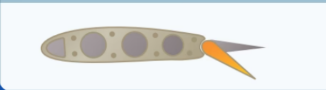
Plain Flap
Aerodynamic Effect:
Increases chamber
Moderate lift increase
High drag at larger deflections
CFD Behavior:
Early flow separation at high angles
Strong wake turbulence
Simple pressure distribution
Split flap
only the lower surface deflectts downward
Split Flap
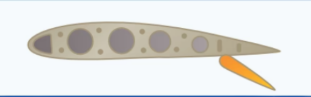
Split Flap
Aerodynamic Effect:
High drag generation
Moderate lift increase
CFD Behavior:
Strong pressure discontinuity
Large separated flow region behind flap
High Turbulent wake
Slotted Flap
includes a slot between wing and flap
Slotted Flap
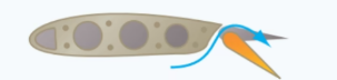
Slotted Flap
Aerodynamic Effect:
Delays flow separation
Increases lift significantly
CFD Behavior:
High-energy air from lower surface reattaches upper surface
Reduced separation zones
Improved lift-to-drag ratio compared to plain flaps
Fowler Flap
extends rearward and downward
Fowler Flap

Fowler Flap
Aerodynamic Effect:
Increases wing area AND camber
Very high lift increase
Moderate drag increase
CFD Behavior:
Larger effective lifting surface
Increased suction peak over extended chord
More complex wake but stable attached flow at moderate angles
Slotted Fowler Flap
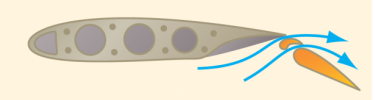
Slotted Fowler Flap
Aerodynamic Effect:
Extremely high lift augmentation
Efficient takeoff/landing performance
CFD Behavior:
Multi-element flow interaction
Strong but controlled vortical structures
Delayed stall significantly
Gouge Flap
adjustable flap system with variable positioning
Gouge Flap
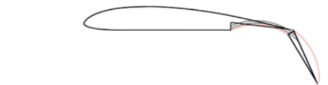
Gouge Flap
Aerodynamic Effect:
Flexible lift/drag control depending on setting
CFD Behavior:
Multiple stable operating points
Flow adapts based on flap configuration
Useful for optimization studies
Junkers Flap
mounted below trailing edge, separated from wing
Junkers Flap
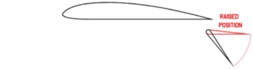
Junkers Flap
Aerodynamic Effect:
Effective at high angles
Strong control authority
CFD Behavior:
Fully exposed flap generates independent airflow field
Strong vortex shedding
Reduced wing interference effects
Zap Flaps
complex multi-link mechanism increasing chord length
Zap Flaps
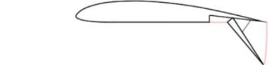
Zap Flaps
Aerodynamic Effect:
Very high lift coefficient
High drag when fully deployed
CFD Behavior:
Strong camber + chord extension effect
Highly nonlinear flow response
Large lift increase but complex wake
Krueger Flaps
deploys from the leading edge downward/forward
Krueger Flaps

Krueger Flaps
Aerodynamic Effect:
Improves stall characteristics
Enhances low-speed lift
CFD Behavior:
Re-energizes leading-edge flow
Delays leading-edge separation bubble
Improves overall pressure recovery
Gurney Flaps
small vertical tab at trailing edge
Gurney Flaps

Gurney Flaps
Aerodynamic Effect:
Increases lift with minimal mechanical complexity
Slight drag penalty
CFD Behavior:
Generates strong trailing-edge vortex
Increases pressure difference between upper and lower surfaces
Improves circulation around airfoil
Drag
is the aerodynamic force that opposes an object’s motion as it moves through air, and it is a critical factor in aircraft performance because it directly affects fuel efficinecy, speed, and overall aerodynamic efficiency
Drag measurements
in aerodynamics, are typically obtained using wind tunnel testing or computational fluid dynamics (CFD), where the drag force is analyzed using coefficients such as the drag coefficient to compate the aerodynamic effciency of diffrent shapes and designs
Skin Friction Drag
Form Drag
Profile Drag
Interference Drag
Parasite Drag
Induced Drag
Zero-lift Drag
Wave Drag
8 Types of Drag
Induced drag
when an airfoil is flown at a positive AOA, a pressure differential exists between the upper and lower surfaces of the airfoil.
the pressure above the wing is less than atmospheric pressure and the pressure below the wing is equal of greater than atmospheric pressure
Vortex
air flows from high to low presure and tends to move outward tward the airfoil tips, causing spanwise flow from the fuselage to the tips. This results in air spilling over the tips and forming a swirling motion known as a ________
Size of lift
Aircraft speed
Aspect Ratio
3 Factors Affecting Induced Drag
Induced drag
is a component of the lift force;
the greater the lift, the greater it will be
weight
L=W in flight so, induced drag will depend on the _______ of the aircraft
Load Factor
relationship of lift to weight ratio is known as
Induced drag
decreases with increasing speed
Induced drag
decreases because as speed increases, the downwash caused by the tip vortices becomes less significant, the rearward inclination of the lift is less, and therefore induced drag is less
High Aspect Ratio Wing
in a _________, the tip vortices only affect a smaller portion of the total wingspan
Tip vortices
swirling air at the wing tips
induced drag
the backward tilt of lift is what creates __________
Wingtip Shape
Winglets
Tip Planks
Wing End Plates
4 Methods of Reducing Induced Drag
Wingtip Shape
can affect the strength of the tip vortices, and designs such as turned down or turned up wingtips have been used to reduce induced drag
Winglets
small vertical aerofoils which form part of the wing tip
Winglets
shaped and angled to the induced flow, they generate a small forward force
Winglets
partly block the air flowing from the bottom to the top surface of the wing, reducing the strength of the tip vortex
Winglets
the small vortex generated by the ______ interacts with and further reduces the strength of the main wingtip vortices
Tip Planks
fuel tanks placed at the wing tips will have a similar beneficial effect to an end plate
will reduce the induced drag
will reduce the wing bending moment
Wing End Plates
a flat plate at the wing tip will restrict the tip vortices and have a similar effect to an increased aspect ratio, but without the extra bending loads
Wing End Plates
will cause parasite drag, and at a higher speeds there may be no overall saving in drag
Internal Balances
External Balances
2 Location of Balances
Internal Balances
they are placed inside the model, thus no interferences are introduced in the wind flow by the balance components, but a mechanical support for the model is always needed to maintain it in the test chamber and change the model orientation if desired
External Balances
are placed outside the model, either inside or outside the test section, and they can disturb the airflow
External Balances
they make it easy to change test models, providing flexibility
External Balances
their complexity varies depending on the number of measurement channels, typically from 1 to 6
Three strut
Two Strut
Single Strut
Sting Mount
4 Mounting Methods
Three Strut Mount
it is a mount that connects to the model near both wing tips and at the aft end
Three Strut Mount
is used most often with external balances
Three Strut Mount
the bottom of the three struts connect to a platform that is instrumented with strain gages
Three Strut Mount
the three movable struts, the AOA, and roll angle can be accurately set and sustained while yaw is provide d by turning the model on the circular section of the platform
Two Strut Mount
supports an aircraft model in a wind tunnel using two struts, typicall attached from below or the sides, resulting in less airflow interference and blockage, which improves flow quality and reduces cost and complexity
Two Strut Model
it is less rigid than a three-strut system, particularly in pitch and roll, making the model more prone to slight movement or vibration that can affect measurement accuracy
Single Strut Model
supports the aircraft model using only one strut, which can be attached either to the top or bottom of the model, resulting in the least expense as well as minimal airflow interference and blockage, allwoing for cleaner flow around the model
Single Strut Model
provides the least rigidity compared to multi-strut systems, making it more susceptible to movement and less stable during testing
Sting Mount Model
has less interference with the model flow field than the one strut mount, but the aft end of the model may be distorted to accept this mount
Single Strut Mount
works very well with internal balances and flow diagnostics
One Component
Three Component
Six Component
3 Types of Balances
Spring Balance (One Component)
is a weighing device that utilizes the relation between the applied load and the deformation of a spring
Linear
the relationship of a spring balance is usually
Linear
if the load is doubled, the deformation is doubled
Strain Gages (Three Component)
measure forces through electrical stretching
Three-Component Balance
detects axial, normal, and bending forces to determint lift, drag, and pitch
Side force
Roll
Yaw
3 things the Three Component Balance cannot measure
Lift
Drag
Side force
Pitch
Roll
Yaw
6 things the Six-Component Balance can Measure
Finite Element Analysis
Numerical method for solving engineering problems
Divides domain into small elements
Used for structural, thermal, and fluid problems
Based on approximate solutions
Finite Element Analysis
divides a complex fluid domain into small elements to numerically solve the governing equations of fluid flow, calculating variables like velocity, pressure, and temperature under specified boundary conditions
Finite Element Analysis
In aerospace engineering, it is used to analyze aerodynamics, propulsion, and fluid–structure interactions, improving aircraft design while reducing the need for costly experiments
Mesh Generation
Process of dividing a complex domain into small elements and nodes so the governing equations can be solved numerically in FEA and CFD.
Stress Analysis
Process of determining the internal forces and stresses within a material or structure when subjected to external loads, pressure, or temperature changes.
Numerical Solution
Using discretization methods to solve the governing equations and obtain the flow field
Mesh generation
A well-refined mesh improves accuracy while balancing computational cos
Numerical Techniques (Numerical Methods)
CFD problems are solved using _________________ and computations to derive accurate results.
Visualization
Results are visualized to comprehend fluid flow patterns and behavior within the system.
Validation
Comparing simulated results with experimental data to validate the accuracy of the model.
Fluid Flow
Movement of liquids and gases in response to forces
Fluid Flow
Governed by conservation of mass, momentum, and energy