M1 Physical Layer
1/55
Earn XP
Description and Tags
Explain how physical layer protocols, services, and network media support communications across data networks.
Name | Mastery | Learn | Test | Matching | Spaced | Call with Kai |
|---|
No analytics yet
Send a link to your students to track their progress
56 Terms
Wired
Physical connection of a device to a local network using a cable. Fast, stable, and predictable.
Wireless
Physical connection of a device to a local network using radio waves instead of cables. Devices connect to a wireless AP or wireless router. Convenient, flexible, but affected by obstacles and traffic.
AP
Access Point.
Wireless Router Components
Wireless antennas (internal or external)
Ethernet switchports (for wired devices)
Internet/WAN port (connects to the ISP modem)
NIC
Network Interface Card. A device need this card to connect to a network.
2 Types of NIC
Ethernet NIC (Wired) - uses ethernet cable
WLAN NIC (Wireless) - uses Wi-fi
Physical connection
It means a device must connect to a local network using wired or wireless media.
Physical Layer
(OSI model Layer 1) is responsible for turning bits into signals and signals back into bits. It takes a frame from layer 2, converts it into electrical/optical/radio signals for transmission, and the receiving device converts those signals back into bits and passes the frame up to the Data Link Layer.
IEEE 802.3
Physical standard for Ethernet
IEEE 802.11
Physical standard for Wi-Fi
IEEE 802.15
Physical standard for Bluetooth
IETF
Govern the TCP/IP standards that are implemented in software. Layer 3 to Layer 7 of OSI model.
IEEE
Govern the physical layer standard that are implemented in hardware (Ethernet & Wi-Fi). Layer 1 and 2 of OSI model. Engineering organizations.
3 Major Functions of Layer 1
Physical Components
Encoding
Signaling
Physical Components
One of the three function of layer 1, which are the actual hardware pieces that allow bits to travel across a network.
Encoding
It is the method a device uses to convert bits (0s & 1s) into a pattern of signals that can travel across the physical medium.
Signaling
It is the method used to physically represent 1s and 0s on copper cables, fiber optic cables, and wireless radio waves. Think of it as the physical “voice” of the network.
Copper cable
It uses voltage changes to represent bits. High voltage = 1; Low voltage = 0.
Fiber Optic
It uses light instead of electricity to represent bits. Light pulse = 1; No light =0.
Wireless
It uses radio wave modulation to represent bits. There are 2 modulation types: AM, FM, and PM.
Amplitude Modulation
A radio wave modulation that change the height of the wave to represent bits. Higher amplitude = 1; Lower amplitude = 0
Frequency Modulation
A radio wave modulation that change the frequency of the wave to represent bits. Faster oscillation = 1; Slower Oscillation = 0
Phase Modulation
A radio wave modulation that change the phase (shift the wave). Phase shift = 1; No shift = 0
Bandwidth
Is the capacity of a medium to carry data. It tells you how many bits per second can be transmitted. It is not the speed of electricity or light. It is how many bits you can fit per second, not how fast they travel.
Data Transfer Terminologies
Bandwidth
Latency
Throughput
Goodput
Latency
Is the time it takes for data to travel from one point to another. The delay before data starts arriving. High would mean slow response.
Throughput
Is the real amount of data successfully transferred per second. The actual bits per second. It is not the same as bandwidth.
Bottleneck
This mean that Throughput cannot exceed the slowest link in the path.
Goodput
Is the amount of actual, usable data delivered per second. Useful data only. It removes: headers, ack, retransmissions, session setup overhead. It is the closest measurement to what the user actually experiences.
Signal Attenuation
The weakening of electrical signals when it travels through copper. Longer cable = weaker signal = more errors. Strict distance limits = 100 meters for most twisted-pair Ethernet.
Electromagnetic Interference / Radio Frequency Interference
It can distort the electrical signal, causing bit errors. Copper cables are vulnerable of this distortions.
Crosstalk
This occurs when the signal on one wire bleeds into an adjacent wire. Effects: bit errors, noise, and reduced performance.
2 Ways to Reduce Interference in Copper Cables
Twisting
Shielding
Twisting
Copper cable technique to reduce crosstalk. It works because magnetic fields cancel each other out. It creates a self-shielding effect.
Shielding
Copper cable technique to reduce EMI/RFI. It blocks external interference.
UTP
Unshielded Twisted-Pair Cable. Is the most common networking cable used in LANs. It contains 4 pairs of wires. Each pair is twisted together. It uses cancellation and twist rate variation to protect itself against interference.
STP
Shielded Twisted-Pair Cable. Is a type of copper cabling designed to provide extra protection against interference. Similar to UTP, but it includes metallic shielding around the wire pairs.
Coaxial Cable
Is an older copper-based medium that was once used in Ethernet networks. UTP has replaced this cable in LANs, but still widely used in wireless and cable internet installations. Two conductors sharing the same axis. Excellent shielding.
4 Main Layers of Coax
Inner Copper Conductor
Plastic Insulation
Metallic Shield
Outer Jacket
Cancellation
When two wires in a pair carry equal and opposite electrical currents: their magnetic fields cancel each other, this reduces crosstalk and EMI/RFI. It is the foundation of UTP’s noise resistance. It is the reason why UTP can work reliably without shielding.
ANSI/TIA-568
An organization that defines the commercial cabling standards used in LANs. It specifies: cable types, max cable lengths, connectors, termination standards, cable testing methods. This is the standard used by installers and network engineers.
IEEE
An organization that defines the electrical performance of copper cabling. It assigns categories based on performance.
Category 3
UTP Cable category. Is originally for voice. 10 Mbps.
Category 5e
UTP Cable category. It supports 1 Gbps. It is the minimum acceptable cable for modern networks.
Category 6
UTP Cable category. It has internal separator to reduce crosstalk. Supports 1 Gbps up to 100m. Supports 10 Gbps up to ~55m. Recommended for new installations.
Category 5
UTP Cable category. It supports 1 Gbps. It is the minimum acceptable cable for modern networks.
Category 6A
UTP Cable category. It supports 10 Gbps up to 100m. It has better shielding and twist control.
Category 7
UTP Cable category. It supports 10 Gbps. It is not officially recognized by ANSI/TIA.
Category 8
UTP Cable category. It supports 40 Gbps. For short distances (up to 30m). It is used in data centers.
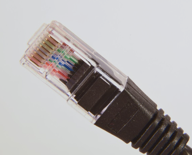
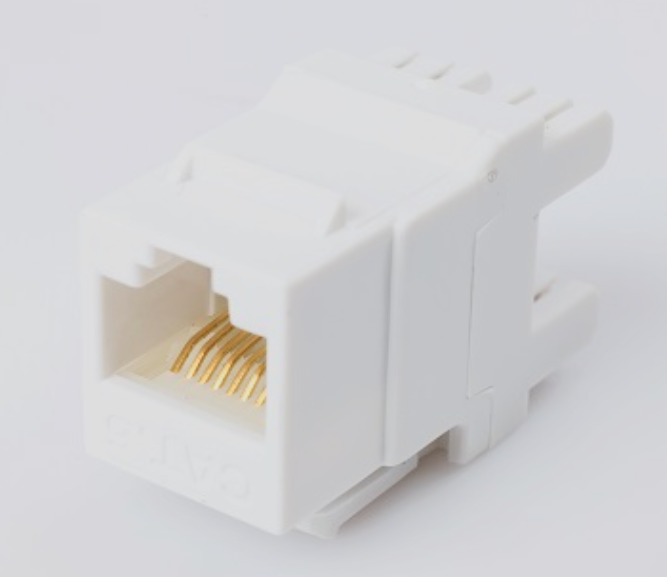
RJ-45 Connectors
It is used to terminate UTP cables. It has a male and female version. The male inserts into the socket to complete the physical connection.
RJ-45 Plug
It is the male version of RJ-45. It is used to connect into a device or patch panel.
RJ-45 Socket
The female version of RJ-45. It is found on switches, routers, wall outlets, and patch panels.
3 Main Cable Types
Ethernet Straight-Through
Ethernet Crossover
Rollover (Cisco Console cable)
Ethernet Straight-Through
One of the 3 cables. Use case: Host → Switch; Switch → Router; Host → Hub. The connectors on both ends of the wiring should be the same. This is the most common Ethernet cable. Different devices.
Ethernet Crossover
One of the 3 types of cable. Use case: Switch ←→ Switch; Router ←→ Router; Host ←→ Host. Same devices connections. The connectors at the end of the wiring swaps the transmit and receive pairs: one end T568A and other end T568B.
Rollover
One of the 3 Types of cable. Use case: PC/workstation → Router console port; PC/workstation → Switch console port. Use for out-of-band management (CLI access). The connectors at the end is the reverse of the other: Pin 1 ←→ Pin 8; Pin 2 ←→ Pin 7. It is the console cable.