practical techniques (paper 1.2.3)
 Call Kai
 Learn
Learn Practice Test
 Spaced Repetition
 Match
Match Flashcards
 Knowt Play
1/46

Earn XP
Description and Tags
all practicals
Name | Mastery | Learn | Test | Matching | Spaced | Call with Kai |
|---|
No analytics yet
Send a link to your students to track their progress
47 Terms
advantages of using a datalogger
higher sampling rate
records multiple reading at the same time e.g(voltage and time)
The time interval is short (too short to measure with a stopwatch)
how to measure the thickness of a wire accurately and precisely
use a micrometer
measure the diameter of the wire at multiple points and multiple orientations
and calculate a mean value
this will reduce the effect of random errors
vernier callipers
stack the discs and measure the thickness across multiple discs.
to work out a mean value for thickness
this will reduce percentage uncertainty and random errors
how to set up a ruler perfectly upright? why is this important?
clamp the ruler vertically using a clamp stand
and use a set square to ensure the ruler is perpendicular
this will reduce the effect of parallax errors and improve accuracy
draw the circuit diagram for a student determining the resistivity of a wire. must include a voltmeter, ammeter, variable resistor, switch and the wire labelled
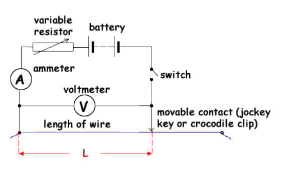
Write a method for a student determining the resistivity of a wire.
At various points along the wire measure the diameter of the wire at multiple places and orientations to calculate a mean value
check for zero error on micrometre
To Find cross-sectional area, A, of wire as: A = πd2 4
At 10cm intervals along the wire and record voltage, v, and current, I,
Calculate Resistance R
Measure length of wire, L, from one crocodile clip to the other, using a ruler
Plot R (y axis) against L and draw line of best fit
with equation: R = ρ/A L
Calculate resistivity: ρ = gradient × A
suggest improvements for determining the resistivity of a wire practical a student can make
use a long wire (reduce percentage uncertainty)
low current to reduce heating
repeat readings to calculate a mean (reduce the effect of random errors)
measure the diameter of the wire at multiple points and multiple orientations ( reduce the effect of random errors)
clamp the wire straight (affect the length)
suggest improvements for determining the acceleration of a free falling object practical a student can make
repeat readings to calculate a mean (reduce the effect of random errors)
use a large height (reduce percentage uncertainty for time)
use a datalogger and light gates instead of a stop watch (removes human reaction time, parallax errors) to improve precision
clamp ruler vertically and check it is perpendicular with a set square
use a smaller or heavier ball bearing- reduce the effect of air resistance
write the method for a student determining the acceleration of a free falling object
measure height, h, from the centre of a ball to the top of the light gate
using a ruler clamped vertically using a set square
Release the ball from the top
Light gate at the bottom will record the time for which the ball passes through
Calculate instantaneous final speed, v, of the ball as: v = diameter of ball/time
Repeat procedure 3 times and calculate mean v
Vary h and record the respective values of v
Given that s = h
u = 0
v= v
a = g
using 𝑣2 = 𝑢2 + 2𝑎s 𝑣2 = 2𝑔s
• Plot v2 against s
draw line of best fit, the gradient (m) will be g=m/2
suggest 3 sources of uncertainty for determining the acceleration of a free falling object practical
human reaction time and parallax error when measuring time
percentage uncertainty using a small height
air resistance
draw the circuit diagram for a student wanting to find the internal resistance and EMF of a cell. must include a resistor, ammeter and voltmeter.
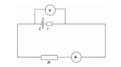
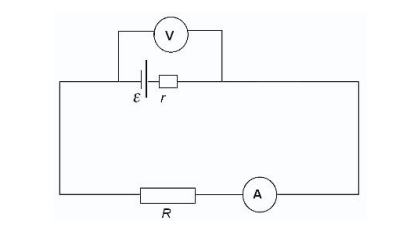
write a method for a student wanting to find the internal resistance and EMF of a cell.
Set up apparatus as shown in the diagram
Measure PD across the terminals, VT, using voltmeter
Vary current in circuit by changing value of load resistance, R using variable resistor, measure pd (V) for several values of I
Repeat several times and find average VT and I
Plot graph of VT (y axis) and I (x axis) and draw line of best fit
with equation: VT = ε − Ir
Gradient is negative (-r)
Y-intercept is EMF
suggest improvements for determining the EMF and Internal Resistance of an Electrical Cell practical
Keep temperature constant by opening switch between readings
Check for zero errors on voltmeters and ammeters
Could use a multimeter as it is difficult to read meters simultaneously when there are fluctuating
Use a cell with a high EMF if the current or voltage values are small
write a method for a student wanting to determine the Viscosity of a Liquid
Zero a mass balance with a 250cm3 measuring cylinder on top
add 200cm3 washing up liquid and record the mass
determine the density of the liquid p=m/v
Measure the mass of the ball
measure diameter of the ball
calculate the volume of ball with a micrometer
Calculate density of the ball bearing
Place elastic bands along the measuring cylinder at 10cm intervals
Start the stopwatch when the ball touches the top of the washing up liquid, lap when the bottom of the ball just passes a rubber band • Record these 2 times
Repeat two more times
do this with balls of varying masses
find the viscosity and work out a mean value for viscosity
suggest 3 safety improvements for determine the Viscosity of a Liquid practical
Be careful of spills
Use gloves if allergic to liquid
Wear goggles to avoid splashes in eye
suggest 5 improvements for determine the Viscosity of a Liquid practical and explain each one
Keep temp roughly the same as it will affect the viscosity of oil
Larger distance between elastic bands will lower percentage uncertainty
Light gates and data loggers can be used to eliminate uncertainty due to reaction time
If ball falls close to wall, repeat reading since the flow will no longer be laminar
If velocity at second band higher than first band, ball bearing might not have reached terminal velocity when you started timing, so move bands further down tube and try again
Suggest one way the metal balls can be removed from washing up liquid in the cylinder.
Use Strong magnet to remove ball bearings from the tube
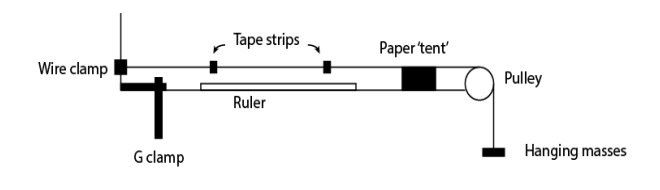
write a method for a student wanting to determine the Young’s Modulus of a wire
Using the micrometre screw gauge, measure the diameter of the wire
Find cross sectional area A = πr2
clamp wire such that it is completely straight
attach two marker to the wire
Measure the distance between the two markers
Add 100g masses at a time and measuring the distance between the markers
Calculate the force applied foreach mass using f=mg
Calculate the extension, x, as x = new length – original length
Repeat until the wire snaps
Calculate stress and strain for each value
Plot a graph of stress against strain
find gradient with a line of best fit to find the Young Modulus
suggest 3 safety improvements for determine the Young’s Modulus of a wire pactical
wear safety glasses whenever wire is under tension as the Wire snaps and can recoil
Place tray underneath to catch the masses when the wire snaps
Do not stand directly under the masses, to avoid injuries
suggest 5 improvements for determine the Young’s Modulus of a wire practical
Use a large distance between the markers at the start, to reduce uncertainty
Use a thick enough wire to ensure that a wide range of values
Area of the wire may not be constant so take several measures and find mean (multiple points and orientations)
For more precise reading, use smaller masses
use a reference marker placed next to the wire for comparison to avoid parallax when measuring extension
suggest 3 measuring techniques that could ensure the accuracy of the extensions (2 marks)
make sure the ruler is vertical by using a setsquare
use a reference marker placed next to the wire for comparison to avoid parallax when measuring extension
Take reading at eyelevel Or place the ruler is as close to the masses as possible
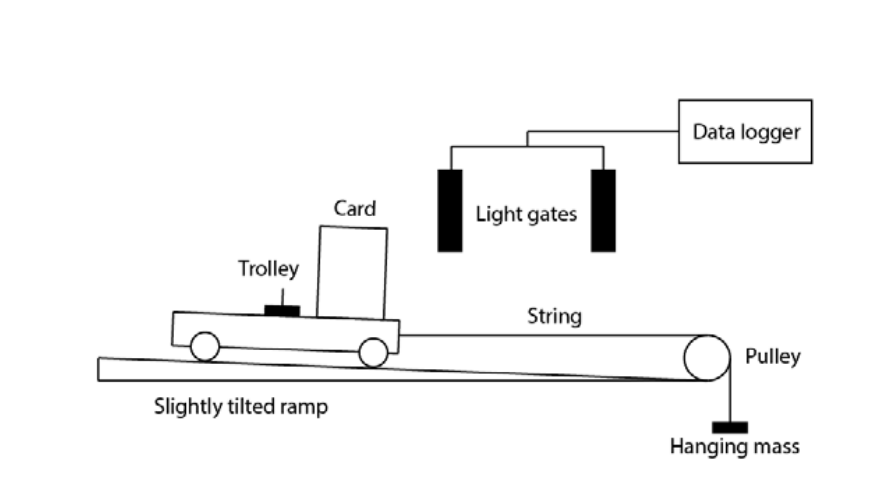
write a method for a student wanting to Investigating Change in Momentum
record the mass of the system(both in the trolley and the hanging M)
and the length of the card
release the trolley, and record the inital and final velocity.
work out the change in velocity to find p=mv
record the value for the time it takes from light gate 1 to light gate 2
then calculate the force f=p/t
repeat 3 times to get a mean value for force
repeat the procedure, moving the masses to the hanger
State 2 assumption for the Investigating Change in Momentum practical
Assume mass of string negligible
Assume the length of the string stays the same so that change in velocity of the hanging masses is the same as the change in velocity of the trolley
State a control vriable the student should follow for the Investigating Change in Momentum practical
-ensure the mass of the system stays constant, only moving masses from the trolley onto the hanger. Not introducing any new masses.
suggest 2 improvements for the Investigating Change in Momentum practical
and explain them (4 marks)
Tilt ramp until trolley is just on the point of moving
Or Using an air track - to account for friction
the light gates can be used to also find acceleration and plot a graph of F=ma
write a method for a student wanting to analyse Collisions between Small Spheres
Record the masses of the two spheres using a mass balance then place them on a flat level table top
Position two metre rulers perpendicular to each other using a set square
Position a video camera above with bird’s eye view and start camera recording
Roll one sphere towards stationary sphere and allow them to collide and roll
Stop recording when both spheres come to rest
Go through each frame of the video, use the rulers to calculate the distance travelled and calculate the time between each frame
Calculate the initial and final velocity of the spheres using Pythagoras Theorem
Angle of travel of the two speeds calculated using trigonometry or calculated by the software
suggest how the student can find the uncertainty of the velocity
by doing more repeated values and then, half the range of repeat readings
why doesnt the student need to account for friction? in the analyse Collisions between Small Spheres practical
Friction cannot be accounted for in 2D
draw the circuit diagram of the finding the current and potential difference across a capacitor. must include a switch, voltmeter, ammeter, resistor and capacitor
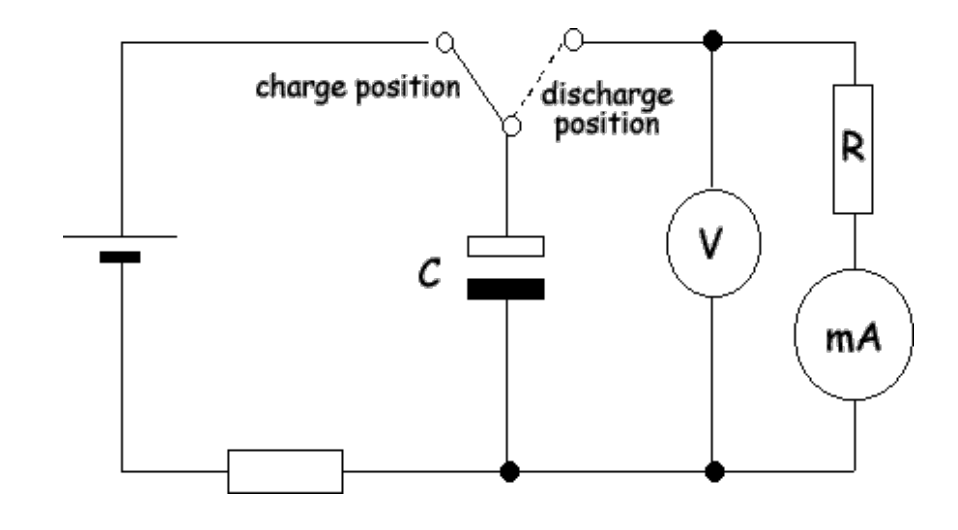
write a method for a student wanting to analyse the PD across a charging and discharging Capacitor (6 marks)
For charging - Close the switch to charging position and start the timer
• Record the PD and current every 10s
• Repeat process 3 times, and calculate mean V and I
• Plot graph of current against time and PD against time
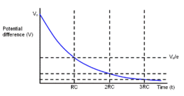
For Discharging - Move switch to the second position for the capacitor to discharge
• Record the PD and current every 10s
• Repeat process 3 times, and calculate mean V and I
• Plot graph of current against time and PD against time
draw a rough graph V against I of what the student should expect to see for a capacitor charging
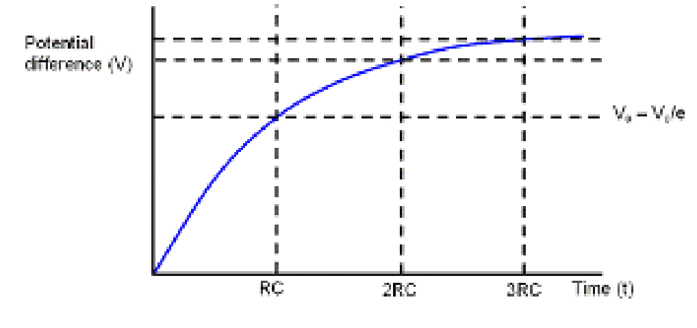
draw a rough graph V against I of what the student should expect to see for a capacitor charging
suggest two safety precaution the student to make for Analyse the PD across a charging and discharging Capacitor practical
Use a low (sub 40V) voltage for an open circuit to work
make sure to discharge the capacitor by making the wires touch, before and after the experiment, to prevent short circuiting.
suggest and explain one improvement for the Analyse the PD across a charging and discharging Capacitor practical (3-4marks)
Increasing the circuit resistance
as this causes the capacitor to discharge slower
therefore measuring a larger value for time reduces percentage uncertainty
give the method for a diffraction experiment
set up a diffractin grating parallel to the screen
measure the distance between the diffraction grating and screen
point the laser perpendicular and at the centre of the diffraction grating.
measure the distance between the first order maxima on the screen.
explain how the diffraction pattern is set up (4 marks)
waves pass through narrow gaps and spreads out
light reaches the walls from ach part of the slits with different path lengths
when the waves meet superpositon occurs. if the waves are inphase constructive interference occurs. forming bright spots
if the waves are in antiphase, destructive interference occurs. forming dark spots
explain how the diffraction pattern would differ if green light was used instead of red light
green light has a shorter wavelength than red light
so green light would diffract less
so the dark points will be closer to the centre.

red-highest wavelength
violet-lowest wavelength
explain how me to increase the accuracy of measuring the angle in a wave diffraction grating with a protractor (2 marks)
measure the angle for the first order on either side and divide by two to find a mean value
this reduces the effect of zero errors
explain how a student can find the theta without using a protractor (3 marks)
measure the distance between the diffraction grating and the screen as l.
measure the distance between the centre maxima and first maximaas x.
use Tan(0)=x/l to find 0
explain why there is a brightspot at the centre (3 marks)
path lengths of A t B is equal
therefore waves arrive inphase
and constructive interference occurs, resulting in a bright spot forming.
explain why monochromatic light is used in the diffraction experiment
emits a very small range of frequencies
so smaller variation in diffraction angle
producing a clearer image
in a diffraction experiment with a laser. explain what happens when the laser is not perpendicular to the diffraction grating (3 marks)
maxima on one side move closer together to the central maximum
maxima on the other side move further away from the central maximum
and the intensity of the maxima would differ on each side of the central maximum
why does the diffraction experiment provide evidence for the wave model of light? (2 marks)
demonstration was reproducible
demonstration provided experimental evidence
what does monochromatic mean in monochromatic light source?
monochromatic light produces a diffraction pattern
coherent waves have a costant phase relationsip
coherent waves have the same frequency and wavelength
explain diffraciton pattern produced in the diffraction experiment (6 marks)
at bright spots, the path difference is zero. therefore the waves arrive inphase. bright spots are positions of constructive interference. points of maximum light intensity.
at dark spots waves will arrive in antiphase. the dark spots are positions of destructive interference. points of minimum light intensity.
in a diffraciton grating d/wavelength = 4.7 how many maxima are visible?
4 on either side and 1 for the central maxima
so 4+4+1=9 maxima