Neural and Muscle Control and Biomedical Signals
 Call Kai
 Learn
Learn Practice Test
 Spaced Repetition
 Match
Match Flashcards
 Knowt Play
1/12

There's no tags or description
Looks like no tags are added yet.
Name | Mastery | Learn | Test | Matching | Spaced | Call with Kai |
|---|
No analytics yet
Send a link to your students to track their progress
13 Terms
The main components of the human body from a control systems perspective
The control system: brain and spinal cord
Actuators: musculoskeletal system
Signal transmission: neurons
Sensors: vision, hearing, touch, etc.
Control System: Brain
Typically described by different regions, which correspond to different functions:
The frontal lobe - located at the front and contains the motor cortex for controlling movement
The parietal lobe - located at the top of the brain, involved in somatosensation and proprioception
The occipital lobe - located at the back of the brain, involved in vision
The temporal lobe - located at the base of the brain, involved in processing sounds
Control System: Spinal Cord
The spinal cord is a thick bundle of nerve tissue that has a highly organised structure
Transmits motor signals to muscles away from the brain (efferent)
Transmits sensory signals from the peripheral nervous system to the brain (afferent)
Signal Transmission: Neurons
Receive signals and transmit them around the body, made of three main components:
Dendrites, receive signals from other neurons
Axons, output signal to other neurons
Soma, cell body
The signals are known as action potentials - potential difference across the cell membrane created by movement of sodium ions
Actuators: Muscles
Three types of muscle:
Skeletal (voluntary) muscle
Smooth muscle
Cardiac (heart) muscle
Generate force by contracting, so are typically arranged in agonist/antagonist pairs.
Not single actuators, but composed of many muscle fibres, arranged in groups, each with a controlling motor neuron that forms a ‘motor unit’.
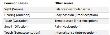
Sensors: Vision, Hearing, Touch
Sensory receptors convert a stimulus into an electrical signal in the nervous system.
The process of converting a physical/chemical stimulus to an electrical signal is called sensory transduction.
Types of Biomedical Signals
Bioelectric
Bioimpedance
Bioacoustic
Biomechanical
Biochemical
Bio-optical
Bioelectric definition
A generic term for all of the electrical signals generated by nerve and muscle cells.
The source is the membrane potential that, under certain circumstances, may generate an action potential.
In single-cell measurements, the action potential is the bioelectric signal. However, in most cases an embedded or surface electrode measures the sum of the action potentials of a large number of cells.
Biolectric signals include those from the brain (electroencephalogram, EEG), muscles (electromyogram, EMG) and heart (electrocardiogram, ECG).
Measurement of Bioelectric Signals
The mechanism of electrical conductivity in the body involves ions as charge carriers.
Measuring bioelectric signals involves converting ionic currents into electric currents that will flow through wires.
This conversion process is carried out by electrodes that consist of electrical conductors in contact with the aqueous ionic (electrolyte) solutions in the body.
Electrodes can be attached internally or to the body surface.
Internal electrodes are typically needle electrodes made from stainless steel and can be single or arranged in arrays.
Surface electrodes usually consist of a flat metal plate with a thin film of conductive electrolyte gel between the plate and the skin to establish contact
(‘dry’ electrodes also exist that rely on sweat to form the electrolyte layer but these tend to produce more noise).
Surface electrodes are commonly made of silver-silver chloride, which conduct well at both low and high frequency and produce few motion artefacts
Signal Acquisition
The raw measured signal passes through a number of signal processing steps:
Signal conditioning - amplification by analogue electronic circuits
Low-pass anti-aliasing filter - must be low-pass filtered at or below Nyquist frequency before sampling to avoid alaising
Analogue to digital conversion - sampling at discrete time steps at a specific sampling frequency and quantisation
Digital signal filtering - specific frequency region is passed by the filter and the rest removed from the signal
Filter Design Examples
Butterworth - maximum in-band flatness but slow roll off
Chebyshev type 1 - fast roll off but in-band ripple
Chebyshev type 2 - fast roll off but out-band ripple
Elliptic - steep roll off but in/out band ripple
Filter Design Specifications
Filter type (low-pass, high-pass, band-pass, band-stop)
Filter design
Cut-off frequency or range of band-pass/band-stop frequencies
Filter order (higher order gives steeper roll-off but more computationally complex)
Robust Filter Design
High order filters tend to be unstable if implemented directly as a high order difference equation.
Instead, filters are usually implemented as a cascade of low order filters.
A cascade of second order filters is known as a biquad design, or second order sequence (SOS)