Electrical energy conversion
1/94
There's no tags or description
Looks like no tags are added yet.
Name | Mastery | Learn | Test | Matching | Spaced | Call with Kai |
|---|
No analytics yet
Send a link to your students to track their progress
95 Terms
What does the open circuit test for in a synchronous machine?
To find the excitation current or the terminal voltage at the rated voltage
How do you perform the open circuit test on a synchronous machine?
Remove any load, apply the excitation, and rotate at a fixed speed because I=0, then E=E0
what is the short circuit test used for in the synchronous machine>?
to find the synchronous reactance
How do you do the short circuit test in a synchronous machine?
the short circuit load is set to 0, and so the excite rotor is E0
how do you find the Xs value for this sychronous machine if
Open circuit test: Eline = 6928, IX=50A
Short circuit test: ISC= 800A
Assuming that the terminals are connected with Y, E0 = Eline/srrt(3) = 4000V
in the open circuit E0=E as I=0
During the short circuit use KVL, E0= Xs*Isc
Xs=E0/Isc= 5 Ohm/phase
Apply KVL for the armature circuit E0=jIXs+E= I(jXs+R)
I=Eo/|Ztotal| = 4000/(R²-X²)
|E|=|I| |R|= 308×12=3696/phase
Eline=E*sqrt(3)= 6420

If you know Xs = 5Ohm/phase how do you get terminal line voltage ?
Apply KVL for the armature circuit E0=jIXs+E= I(jXs+R)
I=Eo/|Ztotal| = 4000/(R²-X²)
|E|=|I| |R|= 308×12=3696/phase
Eline=E*sqrt(3)= 6420
what does the equivelent circuit for a permanent magnet synchronous motor look like?
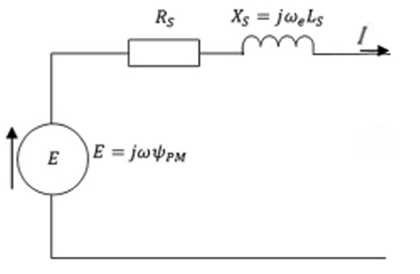
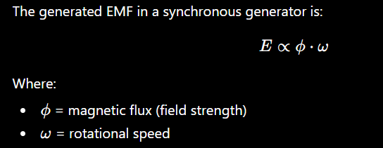
What is the internal voltage induced in the rotor by the permanent magnet in a PMSG
|E| = omega^e * flux
omega e is the angular frequency
the flus is the permanent magnetic flux linkage
What assumption is made about the magnetic flux density in the permanent magnet synchronus generator?
The magnetic flux density distribution in the rotor is generally assumed to be nearly sinusoidal so the flux can be described as a vector, and the internal voltage E induced in the stator winding by the permanent magnet flux can be expressed as |E| = omega^e * flux
What do the stator current and stator reactance do in a PMSG during load conditions to the magnetic field?
‘During load conditions, the stator current and the stator reactance in the stator winding produce their own magnetic field, which is added to the field already generated by the magnets
what type of equivelent circuit for a PMSG is used for their magnetic properties?
The dq equivelent circuit, where Ld= Lq
The d-axis is set in the direction of the permanent magnet's magnetic flux, and the q-axis is set at a 90-degree electrical angle from the d-axis

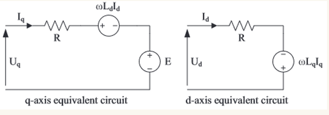
What are the d and q axis in this equivelent dq circuit of a PMSG
The d-axis is set in the direction of the permanent magnet's magnetic flux, and the q-axis is set at a 90-degree electrical angle from the d-axis

equations for dq equivelent circuit
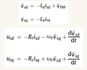
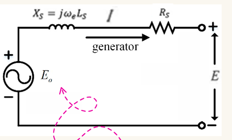
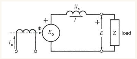
What is Eo in this diagram?
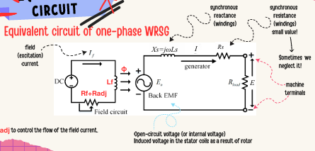
E0 is the open circuit voltage, (internal voltage) this is induced by stator coils as a result of the rotor magnetic field produce by excitation current IX in the field windings
how does the type of wind turbine generator effect the configuration of the WT?
A in-direct drive will have a gear box, and a direct drive will not have a gear box
what is the difference between a direct and an indirect drive generator?
A direct drive the generator speed > blade speed
in an in direct drive the generator speed= blade speed (therefore machine must rotate slowly)
Define a synchronous generator
electrical machine that converts mechanical power into AC electrical power at a particular voltage and frequencye, also called the synchronous frequency or supply frequency
What is a major difference between synchronous machines and induction machines?
Synchronous machines do not depend on induced rotor currents, instead their rotors contain permanent magnets or field windings that receive power from an external source.
What is the RMF created by in an induction machine?
The stator windings which also induces a current in the rotor
What is the RMF created by in a synchronous machine?
It is created only by the state, the rotor magnetic field is magenetically locked with this state created RMP and rotates at the same speed
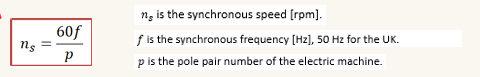
What does the operation speed of a synchronous motor depend on? What equation is useful for this?
The number of pole pairs cant change (depending on machine design) so operation speed changes with the supply frequency
What are the differences between sizes of the salient pole and cylindrical rotors?
Size - Salient pole rotor larger diameter, smaller axial length versus cylindrical
What are the differences between usages of the salient pole and cylindrical rotors?
Usage - salient poe rotors used in low speed (high windage losses) wheras cylindrical are used in high speed
What are the differences between pole numbers of the salient pole and cylindrical rotors?
Salient poles are used for 4 or more poles, non salient pole rotors are usually used for rotors with 2 or 4 poles.
What are the differences between construction of the salient pole and cylindrical rotors?
Salient rotors are supported by pole shoes?
Cylindrical rotors are made of solid steel
what are distributed windings
When the windings are placed in slots around the airgap
what are the field windings
These are the rotor windings, these are usually energised with slip rings and brushes with DC sources
what does it mean is the rotor is energised by slip rings and brushes for the excitation?
The excitation is separated from the stator so the stator.
In an induction motor the state must absorb reactive power from the grid to energise the rotor
However in a synchronous machine the stator does not need to use reactive power
what are the two types of permanent magnet rotor?
Mounter or on the surface
what is a benefit of PM synchronous generators (to do with efficienct)
Since there is no need for external excitation to generate the magnetic field in the rotor, there is less generated head and electrical losses
What is a benefit of PM synchronous motors (to do with assemby)
There is no need for a slip ring or brush assembly
issues with a PMSG (permanent magnet synchronous generator) to do with magnetic field control
Dont have control over the strength of the field as it depends on the magnets and their configurations. Generated voltage is dependent on the rotational speed only. In externally excited generators you can control voltage with the flux.
Issues with PMSG materials
Permanent magnets made from rare earth metals, sustainability issues, and permanent magnets are expensive.
Hard to remove and maintain the magnets
What issue is caused by lack of magnetic field control in PMSG?
Since V is controlled by speed and flux, and flux is fixed, only speed can be used to control voltage. So you need a variable frequency drive for the variable speed operation and gradual starting due to rotors inertia
diagram of a WRSG
This is a wound rotor synchronous generator
turbine, gear box, sychronous generator (3 phase DC output), slip rings to connect to a DC exciter (with AC input)
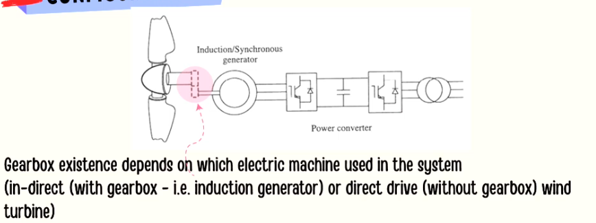
Variable speed turbine with power converter diagram
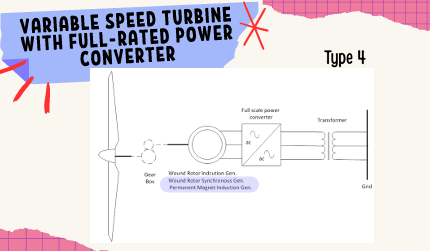
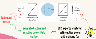
What does a full power converter do?
allows full speed control and generative active power and reactive power are fully controlled. So the GSC exports whatever the grid is asking for.
what does gearbox existance depend on?
What kind of electric machine is used in the system. Indirect = gearbox, direct - no gearbox
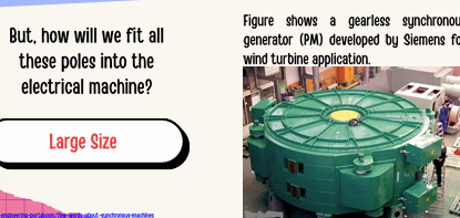
What is are the trade offs of using a gearless synchronous generator?
Many poles are needed which is hard to fit into one eletrical machine, this is done beacuse this does save losses in teh gearbox.
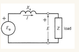
What is the equivelent circuit of the one phase WRSG
Radj controls the flow of the field current
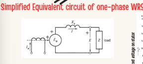
simplifie equivelent circuit of a one phase WRSG
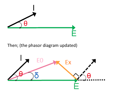
steps to draw a phasor diagrm for a machine
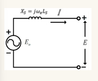
assume Rs = 0
need to know theta, the angle between current and terminal voltage
Calulcate the voltage across the synchronous reactance, Xs. Ex=j I Xs
E_0=E_x+E
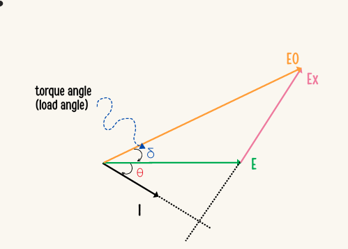

what happens to this phase diagram is E0 gets reduced?
The torque load angle changes, increases>
What does it mean if there is an isolated load?
The generator is directly connected to the load
What are the types of isolated load?
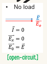
No load
Resistive load
Capacitive and inductive load
What is a No load load?
This is an open circuit where I=0 and Ex=0 and E=E0
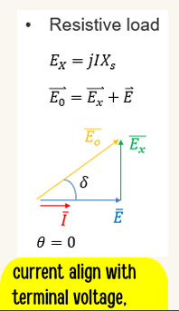
What is a resistive load and what does phasor diagram look like?
This is where the terminal voltage is in phase with the current, => theta=0 so cost theta = 1, provides real power and the rotor field is ahead of the state field by $\delta$
What is capacitive and inductive load on a phasor diagram?
This si when the terminal voltage E is leading or lagging current I by 90 degrees, theta is not 0, so consuming or generating reactive power. delta = 0 and E0 and E are in phase, but their magnitudes will be different depending on if the load is inductive or capacitiveW
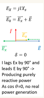
What does the phasor diagram of an isolated load look like when it is capacitive
E0 and E are in phase with eachother but E>E0, so it will suppy reactive power to the grid

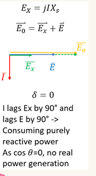
What does the phasor diagram of an inductive load look like?
Eo>E so it is consuming reactive power from the grid. There is no real power generation.
What is an under - excited phasor diagram?
This is when E0<E which means it is a capacitive load, so it is producing purely reactive power. I lags Ex and leads E
What is an over excited phasor diagram?
This is when E0>E, which means the generator is consuming reactive power, this is inductive

what is the current lagging and leading in an under excited generator?
I lags Ex by 90 degrees and leads E by 90
what is the current lagging and leading in an over excited generator?
I lags Ex and lags E by 90 degrees

How do you control power in a synchronous machine?
Changing the torque that is being applied to the shaft of the machine


what is the mechnical angle?
The actual physical rotation of a mechincal component
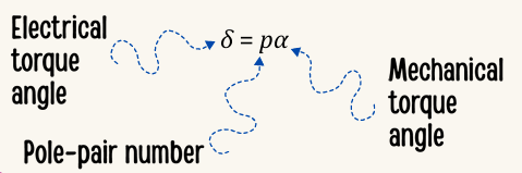
What is the electrical angle?
The progression of the AC waveform over times
What is mechincal torque angle?
The angle between the rotor and the state magnetic fields
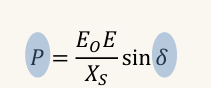
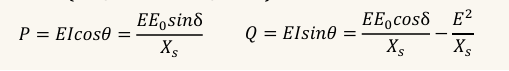
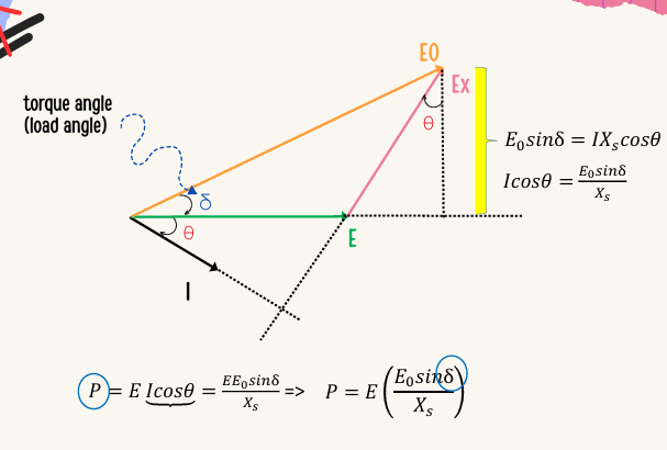
What is the equation for active power from torque angle delta?
(P=XsE0Esin(δ) )
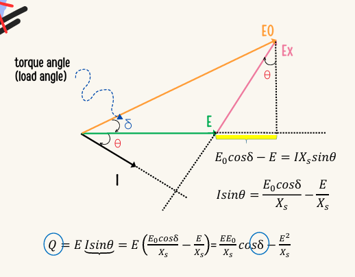
equation for reactive power from torque angle?
Q=XsE0Ecos(δ)−XsE2
steps to get these power equations of a synchrnous generator with respect to torque angle
E_0=E_x + E (1)
assume that E<E_0, so E_o<δ = E0(cosδ+jsin(δ)) (2) (inductive)
get I in terms of circuit parameters given: Ex=jIXs → I=Xs−jEx (3)
use the apparent power equation S=E I* = P+jQ (4)
sub (2) into (1) to get Ex=E0−E=E0cos(δ)−E+jE0sin(δ) (5)
sub equation 5 into equation 3 I=Xs−j(E0cos(δ)−E+jE0sin(δ)) = XsE0sin(δ)−Xsj(E0cos(δ)−E)
used I* from (6) to get S=EI* = P+jQ = E{XsE0sinδ+Xsj(E0cosδ−E) }
what is the active power from the torque angle phasor diagram?
How do you get the reactive power from the phasor diagram
What is a power converter?
Device to change form of electrical energy between AC and DC, such as voltage current or frequency from one form to another
Why do you need converters
Most renewable energy technologies produce DC power therefore power electronics and control equipment are needed to convert it into AC power
What decides which switching device to use in a power converter?
Their power handling capabilities and their switching speed
What is the power handling capabilities of the thyristors?
increasing
BTJ
MOSFET
IGBT
IGCT
GTO
What is the order of the switching speed of thyristors
increasing speed
GTO, IGCT, IGBT, MOSFET, BJT
what is the most common type of self commutated converters?
DC link converters, these can be VSC or CSC
what is a self commutated converter - what does it use?
Use switchable semiconductors and adopt PWM switching methods. may transfer active power in both directions (AC→DC, DC→AC) and can control the AC side reactive power in both directions (inductive and capacitive)
what is a self commutated converter - what switching methods?
and adopt PWM switching methods.
what is a self commutated converter - is it bi or uni directional?
may transfer active power in both directions (AC→DC, DC→AC)
what is a self commutated converter? what can it do about reactive power?
can control the AC side reactive power in both directions (inductive and capacitive)
what type of thyristors are used for PWM switching?
Use IGBT or GTs,
what is usual frequencies of PWM
8-20kHz
What are the risks with PWM?
rate of switching is limited by losses, inverter efficency can still be 94%
May produce harmonics and inter hamonics, in range of kHz, but there are relatively easy to remove with small filters
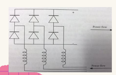
What is this?
This is a diode bridge rectifier for three phase supply with inductors for filtering?

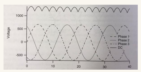
what is the output of this look like?
What is a VSI
a voltage source converter - this operates with a constant DC voltage - most common type used in WTs
What is a CSI?
This is a current source inverter, operates from a constant DC current
What is more common in a WT, a VSI or a CSI?
A VSI
When are CSIs used?
Used to supply high power factor loads where the imperednce constant or decareasing at harmonic frequencies. Whcih
which circuitry is more complex between a VSI and a CSI
CSI is more complexW
What are the two main VSI types?
Six pulse inverters
PWM
How does a 6 pulse inverter work?
The inverter draws current from the AC system in 6 distinct pulses
uses 6 rectifier devices to farm a three phase full wave bridge
bridge switches on and off the DC source through the switches at specific time intervals
how does PWM inverters work
This is a n AC signal synthesizes by the high frequency switching on and off the supply to create pulses of a fixed height

How do you calculate the real power output of this synchronous machine?
Use the equation P=Xs3EoEsin(δ)
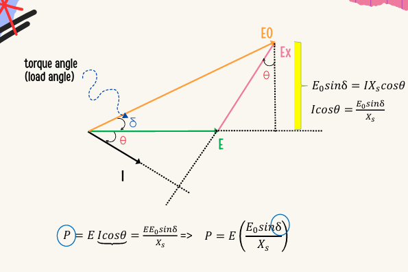

How do you draw the phasor diagram for this kind of machine?
We know I is leading E by θ - draw E flat and I at angle θ (ACW) with E
We know E0 is leading E by δ so we can draw E0at angle δ (ACW) with E
We can ignore R_s
This means that E_x is purely inductive/capacitive, so it will be 90degrees from I
Draw E_x from end of E arrow in perpendicular direction to I