P3.2 - Simple cicuits
1/77
There's no tags or description
Looks like no tags are added yet.
Name | Mastery | Learn | Test | Matching | Spaced | Call with Kai |
|---|
No analytics yet
Send a link to your students to track their progress
78 Terms
Circuit symbol: cell
Single cell — short line (negative) and long line (positive)
Circuit symbol: battery
Two or more cells in a row
Circuit symbol: switch (open vs closed)
Open switch: gap in the line; Closed switch: complete line
Circuit symbol: fixed resistor
Rectangle
Circuit symbol: variable resistor
Rectangle with an arrow through it diagonally
Circuit symbol: thermistor
Rectangle with a line bent at 45° through it
Circuit symbol: LDR
Circle with a resistor symbol inside and two arrows pointing INWARDS
Circuit symbol: LED
Diode triangle with two arrows pointing OUTWARDS (often in a circle)
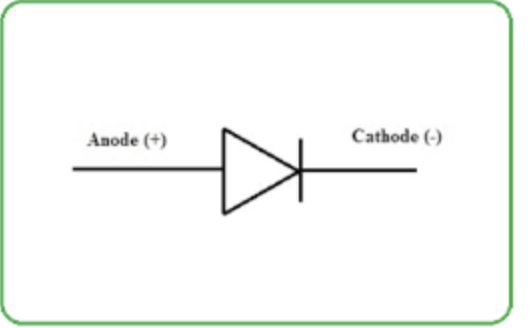
Circuit symbol: diode
Triangle pointing to a vertical line (arrow shows direction of conventional current flow)
Circuit symbol: lamp
Circle with an X inside
Circuit symbol: ammeter
Circle with an A inside
Circuit symbol: voltmeter
Circle with a V inside
Circuit symbol: motor
Circle with an M inside
[DRAW: one reference image showing all key circuit symbols — cell, battery, switch, resistor, variable resistor, thermistor, LDR, LED, diode, lamp, ammeter, voltmeter, motor]
![<p>Circle with an M inside </p><p>[DRAW: one reference image showing all key circuit symbols — cell, battery, switch, resistor, variable resistor, thermistor, LDR, LED, diode, lamp, ammeter, voltmeter, motor]</p>](https://assets.knowt.com/user-attachments/c7212d41-1e36-431b-b583-8a020a8ff390.png)
Function: cell/battery
Provides circuit with a source of potential difference (energy per unit charge); battery = two or more cells
Function: switch
Turns the circuit on (closed) or off (open)
Function: fixed resistor
Limits the flow of current; has a resistance that cannot change
Function: variable resistor
Resistor with a slider that can change its resistance; used in dimmer switches and volume controls
Function: thermistor
Resistance depends on temperature — as temperature increases, resistance decreases (and vice versa)
Function: LDR (light-dependent resistor)
Resistance depends on light intensity — as light intensity increases, resistance decreases (and vice versa)
Function: motor
Converts electrical energy into mechanical energy
Function: diode
Allows current to flow in one direction only; used to convert AC to DC
Function: LED (light-emitting diode)
Equivalent to a diode but emits light when current passes through; used in aviation lighting, TVs, road signs
Function: ammeter
Measures current in a circuit; connected in SERIES
Function: voltmeter
Measures potential difference across a component; connected in PARALLEL
Resistance of ammeter and voltmeter in exams
Taken as negligible
Key rules for drawing a circuit diagram
(1) Must have an energy source (cell, battery, or power supply).
(2) Must be a closed path/complete circuit — electrons need a complete loop for current to flow.
(3) Ammeter in series; voltmeter in parallel.
(4) Current flows from positive to negative terminal (conventional current)
What is potential difference?
The amount of energy transferred per unit of charge passing through the terminals; 1 V = 1 J/C
Units of potential difference
Volts (V); 1 V = 1 joule per coulomb (1 V = 1 J/C)
How is potential difference measured?
With a voltmeter connected in parallel across the component; described as measuring voltage "across" the component
Relationship between current and PD
Current and potential difference are directly proportional — more current means more PD (and more electrons moving around the circuit)
What is resistance?
The opposition to current; higher resistance = lower current
Good conductors vs insulators (resistance)
Good conductors: low resistance; Insulators: high resistance
Symbol and unit of resistance
Symbol: R; Unit: Ohms (Ω) — Greek capital letter Omega; 1 Ω = 1 volt per ampere (1 V/A)
How can resistance of a circuit be increased?
Adding resistors or variable resistors
Assumed resistance of wires and batteries in exam questions
Negligible; every component technically has resistance but wires and batteries are assumed to be zero
How does resistance affect current?
Greater resistance → lower current for a given PD; Lower resistance → greater current for a given PD
Equation linking V, I, R
V = I × R; where V = potential difference (V), I = current (A), R = resistance (Ω)
Worked example approach (V = IR)
Step 1: List known quantities; Step 2: Write equation; Step 3: Substitute values; Step 4: Calculate
Fixed vs variable resistors
Fixed: resistance stays constant once set; Variable: resistance can be changed by changing the length of wire used
How does wire length affect resistance?
Longer wire = more resistance; shorter wire = less resistance
Components whose resistance CHANGES with conditions
Lamps, diodes, LEDs, thermistors, LDRs — resistance changes with current, temperature, or light
Thermistor rule
Hotter → resistance decreases; Cooler → resistance increases
Uses of thermistors
Temperature sensors in ovens, fire alarms, digital thermometers
LDR rule
More light → resistance decreases; Less light → resistance increases
Typical LDR resistance values
Dark: resistance very large (millions of ohms); Bright light: resistance small (tens of ohms)
Uses of LDRs
Light sensors — automatic street lights, security lighting, garden lights
How to identify symbols with arrows
Arrows pointing TOWARDS = light-dependent (LDR); Arrows pointing AWAY = light-emitting (LED)
What is a linear component?
A component whose I-V graph is a STRAIGHT LINE — obeys Ohm's Law, has constant resistance
What is a non-linear component?
A component whose I-V graph is NOT a straight line — does not obey Ohm's Law, resistance changes
Examples of linear components
Fixed resistors, wires, heating elements
Examples of non-linear components
Filament lamps, diodes, LEDs, LDRs, thermistors
I-V graph: fixed resistor
Straight line through the origin (directly proportional); gradient = 1/R; constant resistance
[DRAW: I-V graph showing straight line through origin for a fixed resistor]
![<p>Straight line through the origin (directly proportional); gradient = 1/R; constant resistance </p><p>[DRAW: I-V graph showing straight line through origin for a fixed resistor]</p>](https://assets.knowt.com/user-attachments/964e8e72-a763-4e1d-90c5-f7431fa11650.png)
Why is a fixed resistor's I-V graph linear?
Resistance is constant — current is directly proportional to potential difference
I-V graph: filament lamp
S-shaped curve through origin; gradient decreases as |V| increases (resistance increases)
[DRAW: I-V graph for filament lamp showing S-shaped curve]
![<p>S-shaped curve through origin; gradient decreases as |V| increases (resistance increases) </p><p>[DRAW: I-V graph for filament lamp showing S-shaped curve]</p>](https://assets.knowt.com/user-attachments/460045ec-9e34-4b79-9854-f3e53bc3f6cf.png)
Why is a filament lamp's I-V graph non-linear?
As current increases, temperature of filament increases → atoms vibrate more → harder for free electrons to pass through → resistance increases → current increases at a slower rate
Filament lamp: reversing PD
Makes no difference to the shape of the curve — graph is symmetrical about origin
I-V graph: diode
Zero current for reverse bias; sharp increase in current for forward bias (above a threshold PD)
[DRAW: I-V graph for semiconductor diode showing flat line for negative V and sharp curve up for positive V]
![<p>Zero current for reverse bias; sharp increase in current for forward bias (above a threshold PD) </p><p>[DRAW: I-V graph for semiconductor diode showing flat line for negative V and sharp curve up for positive V]</p>](https://assets.knowt.com/user-attachments/66f97270-1f9d-4b10-ad96-b70badfbe15f.png)
What is forward bias?
When current flows in the direction of the diode's arrow symbol — diode allows current; shown by sharp increase in current on right side of graph
What is reverse bias?
When the diode is switched around — very high resistance, no current flows; shown by zero current on left side of graph
Interpreting I-V graph gradient
Straight line, steep gradient = low resistance (high current for given V); shallow gradient = high resistance
[PAG] Aim of I-V characteristics experiment
Use circuit diagrams to construct appropriate circuits to investigate the I-V characteristics of a variety of circuit elements (fixed resistor at constant temperature, filament lamp, diode)
[PAG] Independent variable
Potential difference, V
[PAG] Dependent variable
Current, I
[PAG] Control variables
Potential difference of the power supply; use of the same equipment (wires, diodes)
[PAG] Equipment list
Ammeter, voltmeter, variable resistor, fixed resistor (100-500 Ω), filament lamp, diode, voltage supply, connecting wires
[PAG] Resolution of measuring equipment
Variable resistor: 0.005 Ω; Voltmeter: 0.1 V; Ammeter: 0.01 A
[PAG] Circuit setup
Fixed resistor (or lamp/diode) in series with ammeter, variable resistor, and voltage supply; voltmeter in parallel across the component being tested
[DRAW: circuit diagram with voltage supply, ammeter in series, variable resistor in series, fixed resistor with voltmeter in parallel]
![<p>Fixed resistor (or lamp/diode) in series with ammeter, variable resistor, and voltage supply; voltmeter in parallel across the component being tested </p><p>[DRAW: circuit diagram with voltage supply, ammeter in series, variable resistor in series, fixed resistor with voltmeter in parallel]</p>](https://assets.knowt.com/user-attachments/c55d47be-204a-40c9-ad7a-f884f4ac1f41.png)
[PAG] Method (step-by-step)
(1) Set up circuit with fixed resistor.
(2) Vary voltage/PD across component using variable resistor (8-10 readings).
(3) Record current value 3 times and calculate average.
(4) Increase voltage in steps of 0.5 V, repeat.
(5) Switch off circuit between readings to prevent heating.
(6) Reverse terminals to get negative readings.
(7) Repeat for filament lamp and diode.
[PAG] Why switch off between readings?
To prevent heating of the component, which would change its resistance
[PAG] Why take 3 readings and average?
To reduce random error and improve accuracy
[PAG] Why reverse the terminals?
To take negative voltage readings and plot the full I-V graph on both sides of the origin
[PAG] Analysis of results
Plot graph of average current against PD;
Straight line through origin = ohmic conductor (obeys Ohm's Law, V=IR);
Curve = non-ohmic conductor
[PAG] Expected I-V shape: fixed resistor
Straight line through origin (ohmic)
[PAG] Expected I-V shape: filament lamp
S-shaped curve (non-ohmic)
[PAG] Expected I-V shape: diode
Flat (zero current) in reverse bias, sharp curve up in forward bias
[PAG] Systematic errors
Voltmeter and ammeter should start from zero to avoid zero error
[PAG] Random errors
Voltmeter and ammeter have some resistance, so readings may be slightly inaccurate;
temperature of equipment could affect resistance (must be controlled);
take multiple readings to reduce random error and uncertainty
[PAG] Safety considerations
(1) High current in thin wire makes wire very hot — don't touch when switched on.
(2) Switch off power supply if burning smell detected.
(3) No liquids near equipment.
(4) Components get hot — careful handling, especially filament lamp.
(5) Disconnect power supply between readings to avoid overheating.