Common-Collector Circuit Small Signal Analysis (BJT)
1/29
There's no tags or description
Looks like no tags are added yet.
Name | Mastery | Learn | Test | Matching | Spaced | Call with Kai |
|---|
No analytics yet
Send a link to your students to track their progress
30 Terms
first thing to check for a circuit with a transistor
check that the transistor satisfies active mode conditions
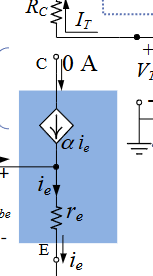
(1) T-model for npn transistor in AC analysis
best for common base to find voltage gain, input resistance seen by source, output resistance seen by load
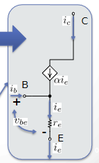
(2) T-model for npn transistor in AC analysis
best for common base to find voltage gain, input resistance seen by source, output resistance seen by load
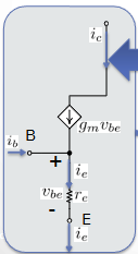
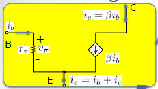
(10) hybrid pi model for npn transistor
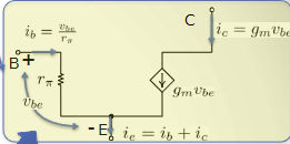
hybrid pi model for npn transistor
use for common emitter/collector and sometimes common base if it’s more comfortable
difference between the hybrid / t models for npn transistor vs pnp transistor
they’re the same but you have to switch the polarity of the voltages and the directions of the currents
how to tell if a circuit is common-base, common-emitter, or common-collector
(this rule doesn’t apply in all cases) → for instance, if the AC ground is directly connected to emitter, then it’s common-emitter
you cannot express any of these small signal parameters with a varying small signal current or voltage
BUT you can express them with signal variables AS LONG AS they can be cancelled out in the final expression
what is Rin
the input resistance, parallel to vi → it’s the resistance that the input signal source “sees’ looking into the transistor input terminal (where vin is measured) with independent sources turned off
what is Rout
the output resistance → the resistance seen by the load looking into the output terminal of the transistor (/amplifier), in parallel with vo
which is being amplified by the transistor? (DC values or AC values)
AC values. DC values are always constant
typical values for the gains in a common-collector circuit
current gain: SLAYYYYYYYYYYYYYY
voltage gain: such an L
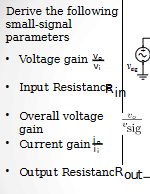
how to find Rin
solve for vin/in (vin and iin both have their own expression that you must find)
how to “reflect” a resistor
the resister for ie wouldve been RL, since , but since we’re getting all the resistances for ib, it’s (1 + beta)RL
RL is in the direct branch of ie, not ib, but we can relate ie and ib together with ib = ie/(1 + beta)
so therefore ie/RL → ib/(1 + beta)RL
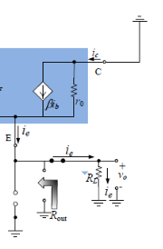
when you’re trying to find Rout, you must:
cut off everything that comes “before” it
here, RL is cut off
how to find Rin and Rout
use VT/IT
rbmr: things are in PARALLEL, not series, if they ….
share two nodes, and usually one is the ground node BUT watch out for if there’s an open circuit in the branch
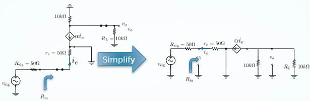
process of analysis for amplifier
almost always try to simplify by….
noticing which resistances are parallel and combining them
when doing a KVL loop, avoid :
current sources
relationship between ie and ic
ic = ie * alpha
always look for equivalent resistance Rin and Rout in»>
small-signal domain, so deactivate all DC sources and short circuit all capacitors
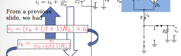
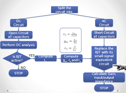
in what situation can you turn off a dependent source in thevenin resistance calculation
if you can prove the dependent source to be equal to 0
in the example in the image, ie must be shown as 0
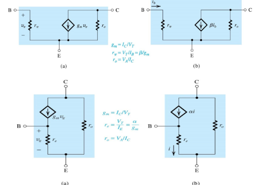
how to tell that you need to take early effect into account
when the question says “VA < infinity” or gives a numerical value for VA; if it says “VA = infinity” ignore early effect
what to do if a problem involves early effect
change the equivalent T or hybrid-pi model to include ro (see images → generally, ro is in parallel with the dependent current source)
what do you notice here
r, is parallel with RL
so you can combine them DUMMYYY
the input resistance looking RIGHT into the base is _____ times the TOTAL resistance in the emitter
(beta + 1)
***input resistance looking right into the base is equal to vi/ib
you can rearrange the relation Rin = vi/ii to be
ii = vi/Rin
neat trick to find io/ii
it generally equals to (vo/vi)*(Rin/RL)
how to simplify circuits so they’re easier to compute