Smart Energy Networks
1/68
Earn XP
Description and Tags
in person exam
Name | Mastery | Learn | Test | Matching | Spaced | Call with Kai |
|---|
No analytics yet
Send a link to your students to track their progress
69 Terms
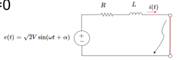
equation for voltage supply of a one phase system
e(t)=\sqrt(2) V sin(\omega*t + alpha)
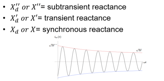
how do you model a synchronous generator with a line fault
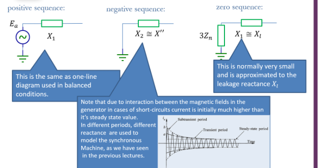
to model this during a fault we need a variable reactance, this is approximated into 3 phases with 3 different reactance values. sub transient, transient and synchronous
all 5 assumptions used for modelling a three phase fault
calculations in per unit
transformers represented as series inductances only
transmission lines are their series reactances only
synchronous machines are constant voltage sources in series with sub transient reactances
induction machines are ignored or treated as synchronous
unit assumption for modelling 3 phase faults
calculations in per unit
transformers assumption for modelling 3 phase faults
transformers represented as series inductances only
transmission line assumption for modelling 3 phase faults
transmission lines are their series reactances only
synchronous machine assumption for modelling 3 phase faults
synchronous machines are constant voltage sources in series with sub transient reactances
induction machine assumption for modelling 3 phase faults
induction machines are ignored or treated as synchronous
what does a bolted short circuit mean?
There is no fault impedance in this circuit
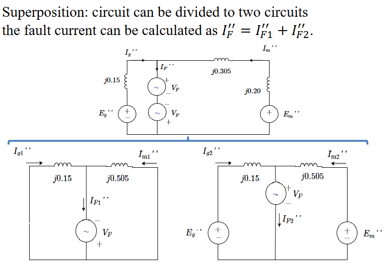
what is the superposition method of solving a circuit after a fault?
This is when it is a large system, and we can’t just do KVL and KCL for the whole thing and then solve simultaneous equations, instead we break the circuit down into multiple simpler circuits, solve them and add the currents together

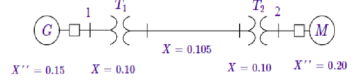
The synchronous generator in this system is operating at
rated MVA, 0.95 p.f. lagging and at 5% above rated
voltage. A bolted short circuit fault happens at bus 1.
Calculate the subtransient fault current
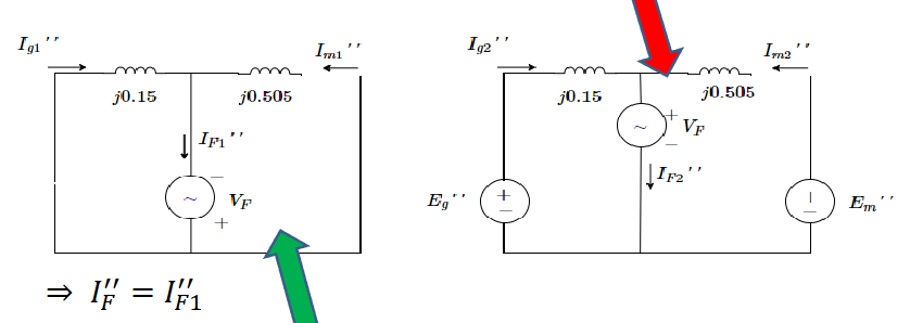
First split it into the two circuits with superposition method, one is the pre fault circuit (right) and the addition one (left). From this we know I_F2 = 0 since this is the pre fault circuit.
Then find the Thevenin impedance, in this example it is the two impedances in parallel with each other, which is the impedance that the fault sees
The fault current is the voltage of the circuit divided by the Thenevin impedance, I_F’’ = V_F/Z_th
Often only the magnitude of this is needed

The synchronous generator in this system is operating at
rated MVA, 0.95 p.f. lagging and at 5% above rated
voltage. A bolted short circuit fault happens at bus 1.
Calculate the the motor and the generator currents not considering the pre fault currents in this example? We know the fault current IF1’’=-j9.0792
Split the circuit into 2, since we have the fault current, we just need to consider how it is split between the two branches in the diagram on the left. I_g=I_f (0.505/0.505+0.15), I_m=I_f(0.15/0.505+0.15)

The synchronous generator in this system is operating at
rated MVA, 0.95 p.f. lagging and at 5% above rated
voltage. A bolted short circuit fault happens at bus 1.
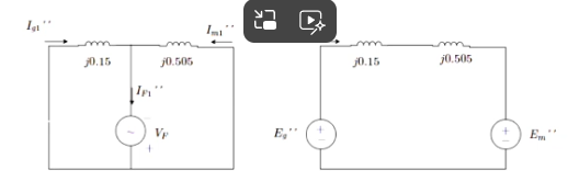
Calculate the the motor and the generator currents considering the pre fault currents in this example? We know the fault current IF1’’, and the I_g1 and I_m1.
since we know Ig1, and Im1, and we know that IF2 =0, we need to find the current IL and then add it to Ig1 and Im1 to get the actual current (superposition method means once we solve each circuit we have to then add them together)
to find IL, we use the apparent power we have, S=1p.u (since its at rated MVA), and we know |S|=|V||I| (magnitudes only), so |I_L|= |S|/|V|=1/1.05= 0.9524|
To find angle of I_L, we do -arcos(0.95), since it has lagging power factor of 0.95
Using I_L=0.9524<18.195 degrees, we get I_m = Im1-I_L (consider directions of current flows), and I_g=Im1+I_L
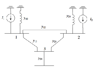
what is the Y bus matrix?
This is when we draw out the norton equivelent circuit of a bus system, then balance the nodes following KCL, and then write these equiations in matrix form to get I_bus = Y_bus * V_bus
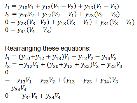
what is the bus addmitance matrix
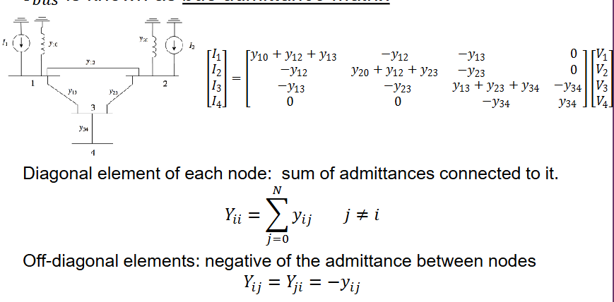
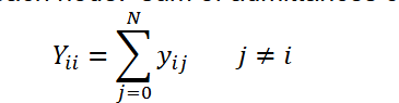
equation for diagonal elements of bus addmitance matrix
Y-ii=sum of (yij) where i does not = j
equation for non diagonal elements if bus addmitance matrix
Yij=Yji=-yij
system model of a fault using a Z bus matrix
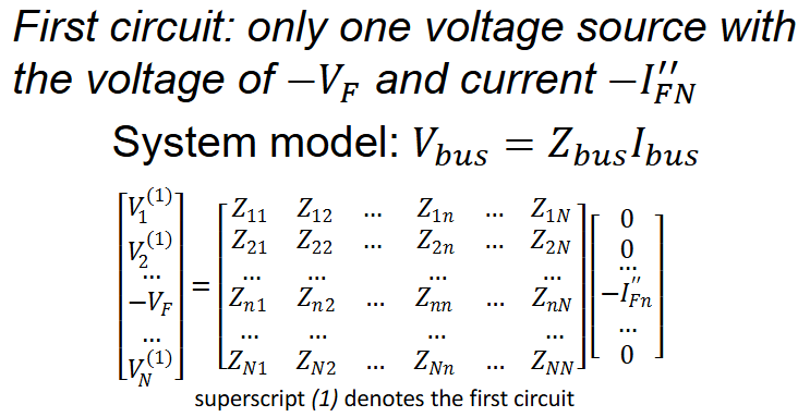
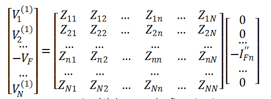
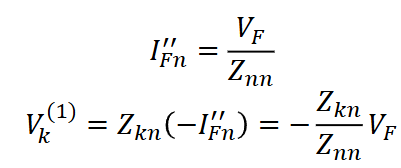
equations for the first circuit in superposition analysis of a fault
where (1) denotes the first circuit
What is V_abc?
Those are the three unbalanced voltages, they can be broken up into 3 balanced votlages, V_012, which are the zero, positive and negative sequence components .
What is V_012
These are the 3 sequence component voltages, zero, positive, and negative.
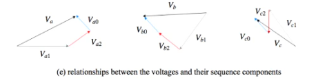
what is the relationship between the voltages (abc) and their sequence components (012)
each of them add up to their voltages. Va1, Va2, Va3 add up to Va, Vb1, Vb2, Vb3 add up to Vb and same for c
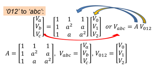
How do you get from V_012 to V_abc?
You multiply V_abc by the matrix A which is defined by the value a
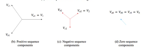
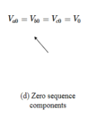
what do the V0 sequency components look like for Va0, Vb0 and Vc0?
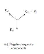
what do the V2 sequency components look like for Va2, Vb2 and Vc2?
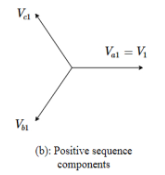
what do the V1 sequency components look like for Va1, Vb1 and Vc1?
Does each piece of equipment always have the same values for impedence for each sequence?
No, each equipment or component might have different values for impedence for each sequence, there is a positive sequence impedance, and negative and a zero
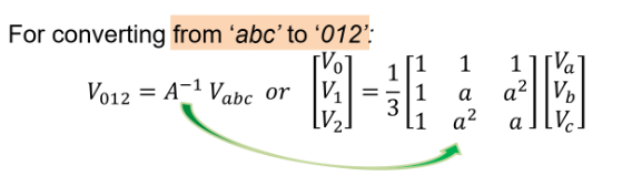
How do you get from V_abc to V_012
Left multiply by inverse of A
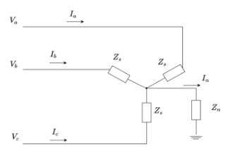
how do you draw the sequence impedence of Y- connected loads?
how do you get a value for Z_012 from equations we already know V_abc=Z_abc*I_abc, and V_abc = A*V_012
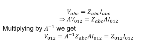
how do you get Z_012 from Z_abc
A^(-1)*Z_abc*A
inverse left multiply by A and then right multiply by A
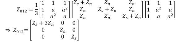
sequency impedences for each sequenc in a Y connected unbalanced network
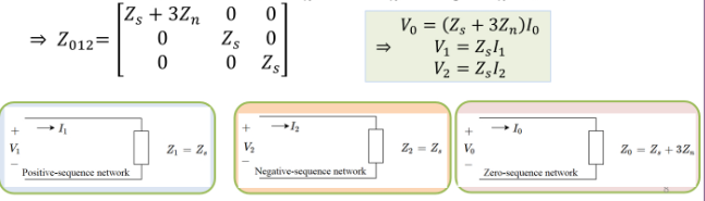
What is Z_n versus Z_s
Z_n is from the centre of the Y connection to ground, and Z_s is for each phase to the centre, a, b, and c

For which sequences does phase sequence effect the phase impedance?
the positive and negative sequences have the same phase impedance, Z1=Z2, but for the zero sequency it returns to the ground, so Z0=Zs+3Zn
zero phase impedance is normally 2 -3.5 times larger than positive/negative impedance
what do the sequency impedances for synchronous machines look like?
how does the frequency of a system change over time, equations not specific values?
this means the rate of change of frequency is equal to the rate of change of \delta which is the rotor angular position
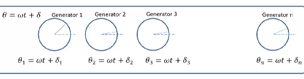
what is $\delta$ in the equation \theta=\omega t + \delta?
That is the rotor angular position with respect to the continuously rotating reference
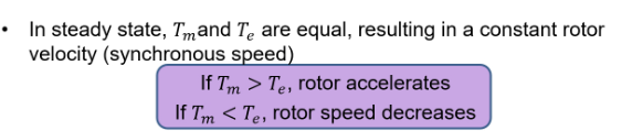
what happens if a generator in a system has a different frequency to the others?
It can no longer exchange active powers with the other generators
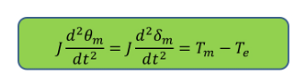
what is the equation for rotor motion?


what is T_m in
That is the mechanical torque supplied by the prime mover
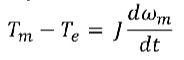
What is Te
electrical torquE
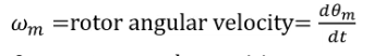
\omega_m
is the rotor angular velocity = rate of change of frequency with respecct to time

what is J?
this is the total amount of intertia of the rotating masses
what is theta _m
that is the rotor angular position
what is concept of the swing equation?
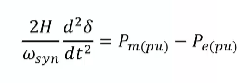
What is the swing equation?

What is each value in this equation?
theta is the rotor angular position with respect to the stationary axis
omega msyn is the synchronous angular velocity of the rotor
\delta is the rotor angular position with respect to the synchrnonously rotating reference

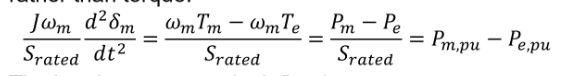
how do you change the swing equation to work in PU?
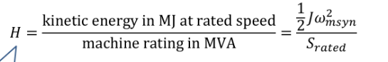
what is the intertia constant?
kinetic energy in MY at the rated speed/machine rating in MVA
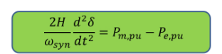
what is the per unit swing equation?
how can a synchrnous machine be simplified?
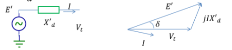
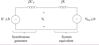
how can the power system that a generator is connected to be represented?
as an infinite bus which is an ideal voltage source with constant voltage

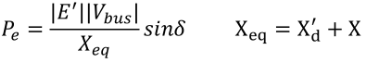
what is the real power delivered to the infinite bus by the generator

what is this?
the power angle curve
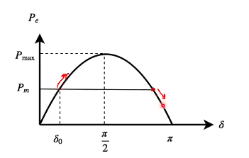
what is the top of the curve called
that is the power angle curve and the top is called the steady state stability limit

what is the point under the first red arrow called?
that is the stable equilibrium

what is the point near the 2nd red arrow called?
that an the unstable equilibiurm
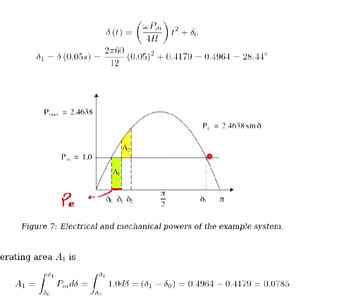
what happens after a sudden step increase of the input power a power curve?
first there will be acceleration as there is power input
then the angle \delta will increase
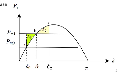
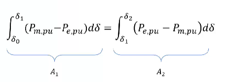
what does it mean if the two areas A1 and A2 are equal?
this is the equal angle criterion, if they are equal the system is stable, because the extra input can be absorbed by the rotor as it is turned into kinetic energg
what is the equal area criterion in an eqeuation for a1 and a2?
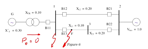
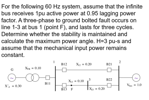
what is the equivelent reactance at the fault at bus 1 shown by the red line?
Xd + Xtr + X12 || X13 +X32

how do you find the currrent at the infinite bus from this?
use P = |V| |I| cos(theta)
|I| = P/|V|*cos(theta)
= 1/1×0.95
I=I< -arcos(0.95)
=1.05263 < -18.195

how do you calculate the machine internal voltage? you already have found current at the bus and the equivalent impedence
E’=V_bus + j X_eq * I
= 1 <0 + j 0.52 × 1.05263 < -18.195
= 1.2812<23.946
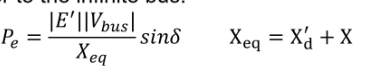
what is the equation for the real power delivered to the infinite bus?
P_e = |E’||V_bus|/X_eq * sin(\delta)
=2.462 sin(delta)

if the equation for the real power delivered to the infinite bus is P_e =2.462 sin(delta), how do you find delta_0?
since you know the Pm = Pe = 1p.u. you can do 2.462*sin(delta)=1
delta = arcsin(1/2.462) = 23.95 = 0.4179 radians


how can this equation be used on the power curve?
if you know the values for the circuit before the fault, (apart from delta) and you know the power in p.u., then you can find the delta zero which is important for the equivelent area criterion