SYSC3313 - Chapter 7 Finite State Machines
1/30
There's no tags or description
Looks like no tags are added yet.
Name | Mastery | Learn | Test | Matching | Spaced | Call with Kai |
|---|
No analytics yet
Send a link to your students to track their progress
31 Terms
Reactive system
Continuously responds to events from the environment. Behavior can be defined in terms of states and transitions rather than sequential computations.
Finite state machine
Mathematical and graphical framework for modelling reactive behavior. Uses states and describes how inputs trigger state changes.
Reactive System context
Can be described using a finite set of states
FSM basics
finite set of states describe a system
always in only one state at a time
state transitions happen due to events or conditions
state diagrams can visualize states and transitions as nodes and directed edges
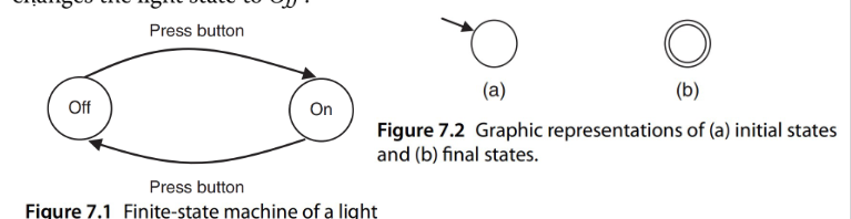
Light bulb FSM example
2 states: ON and OFF
ON to OFF transition: Press button
OFF to ON transition: Press button
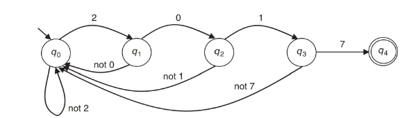
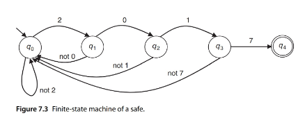
Safe FSM example
A safe that is locked with the code 2-0-1-7
Deterministic Finite state machine (Deterministic Finite automation)
The next state is uniquely determine by the current state and input. A single, well-defined execution path.
Also called finite acceptors because they accept or reject input strings.
Finite acceptor
A deterministic FSM. It accepts or rejects input strings. Suitable for embedded systems because of deterministic behavior.
DFA Key elements
finite set of states
finite set of input symbols
transition function
initial state specifies execution start
set of final states defines acceptance conditions
DFA transition function
Maps state and input symbol pair to a unique next state.
DFA benefits
Rigorous reasoning about system behavior. Supports formal analysis and verification.
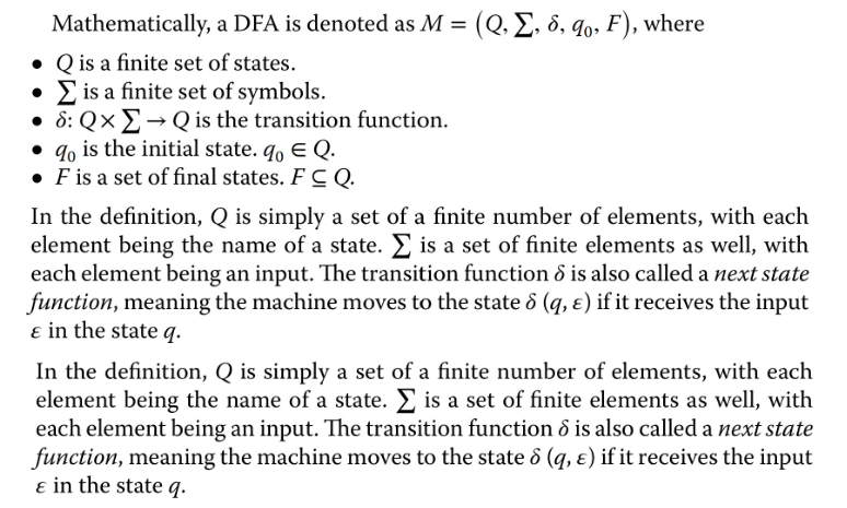
Mathematical model of DFA
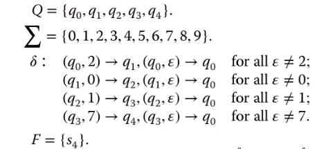
M = (Q, sum, delta, q0, F)
Q: set of finite states
sum: a finite set of symbols for inputs
delta: Q * delta aka transition function
q0: initial state which is in the set Q
F: is the set of final states
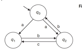
Example Mathematical model for DFA
State transition table
Tabular form of state transition diagramB
Benefit of state transition tables
Useful for implementation and analysis. Compact and precise representation of system behavior.
Types of FSMs that generate outputs
Moore
Mealy
The two can be converted from one to the other
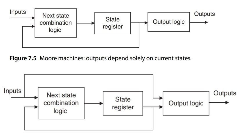
Moore machine
A DFA whose output depends only on the current state.
The output is generated when entering the state.
Mealy Machine
A DFA whose output depends on the current input as well as the current state.
Outputs are associated with transitions rather than states. As opposed to Mealy machines where the output is within the state node.
Moore machine benefits
Easy to analyze because output timing is state based.
Moore machine uses
When outputs should be stable between transitions
Moore machine mathematical model
M = (Q, sum, O, delta, lambda, q0)
Q is a finite set of states
sum is a finite set of input symbols
O is a finite set of output symbols
delta is Qxsum aka transition function that produces Q
lambda is Q→O, the output function
q0 is the initial state that is in the set Q
Notice how there is no final state, since it’s not an acceptor (language recognizer) but a producer of outputs.
Mealy Machine mathematical model
M = (Q, sum, O, delta, lambda, q0)
Q is a finite set of states
sum is a finite set of input symbols
O is a finite set of output symbols
delta is Qxsum→Q aka transition function
lambda is Qxsum→O, the output function
q0 is the initial state that is in the set Q
Notice how there is no final state. The difference with Moore is in the lambda function which also uses the input.
Moore vs Mealy machine decision flow
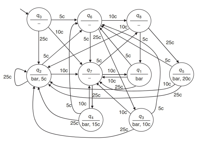
Moore Machine Vending Machine Example
A vending machine sells candy bars for 20 cents and accepts 5c, 10c, and 25c coins. The states represent the accumulated balance (0c, 5c, 10c, 15c). When the total inserted reaches or exceeds 20 cents it should dispense the candy bar and any change then return to state 0c. No output otherwise.
Draw the state diagram
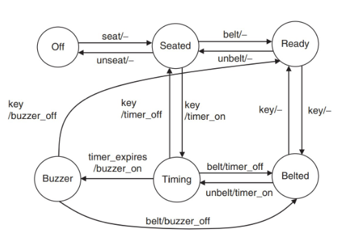
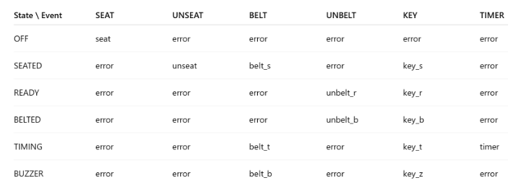
Mealy Machine of a Seat Belt reminder system
Initial state is car engine off
The driver can turn the car on or put the seat belt on
If engine is on and driver is not seat belted, buzzer timer turns on. If driver put the belt on before timer expiry, the the timer turns off
If timer expires, buzzer turns on. When belted, buzzer turns off
If the car is turned off at any point, the timer or buzzer is turned off
The driver can unbuckle at any point
The drive cannot leave the seat while buckled or engine is on
Draw the FSM diagram
Nondeterministic finite automation
A state and input may lead to multiple possible next states. Transitions can also occur without any input event.
Every NDFA has an equivalent DFA
Uses for NDFA
Model unspecified or uncertain behavior. More compact but not directly implementable.
How to program FSM
conditional statements, handling state and input combinations →difficult to maintain with more complexity
Downsides of using conditional statements for FSM code
Difficult to maintain as system complexity grows
Table based FSM cocde
Table indexes states and input events to determine the transition function. Control logic is separate from state transition data.
State machine diagram becomes a matrix of actions.
Table row has current states, the columns have inputs events. Each entry contain what should happen, aka the function that should be called.
You would make the entries into pointers (ie just put function name).
What should be in the function? Any required actions + change the current state (global variable)
To define/implement:
states and events as enums
define the transtion table as an array of arrays
define each function in the transition table
in main(), in a loop, get the event, then call the function from the table according to the gotten event.
Benefit of table driven implementation of FSM
No need for long, nested, complex switch statements
Control logic is separate from state transition data. Improved readability and maintainability.