8.4 The Source-Free Parallel RLC Circuit
1/4
There's no tags or description
Looks like no tags are added yet.
Name | Mastery | Learn | Test | Matching | Spaced | Call with Kai |
|---|
No analytics yet
Send a link to your students to track their progress
5 Terms
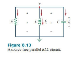
The Source-Free Parallel RLC Circuit
The source-free parallel RLC circuit is a circuit whereby the resistor (R), inductor (L), and capacitor (C) are all in PARALLEL with one another - meaning that they have the same VOLTAGE.
For parallel RLC circuits, we will focus on calculating the voltage response equation — just like how we calculated current for a SERIES circuit.
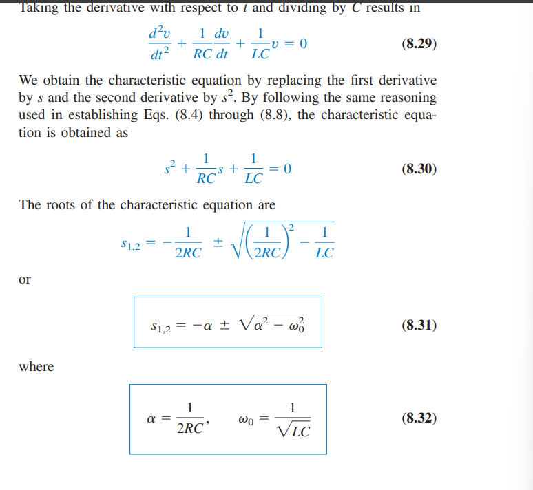
Characteristic Equation + Dampening Factors
The characteristic equation is derived by applying KCL to the top node of the parallel circuit and realizing that since all current leaves from that node, their sum must be 0.
From there, we differentiate each term until a 2nd-order differential equation is obtained. From there, we follow the same process as with the series circuit and simply solve for the characteristic equation’s roots.
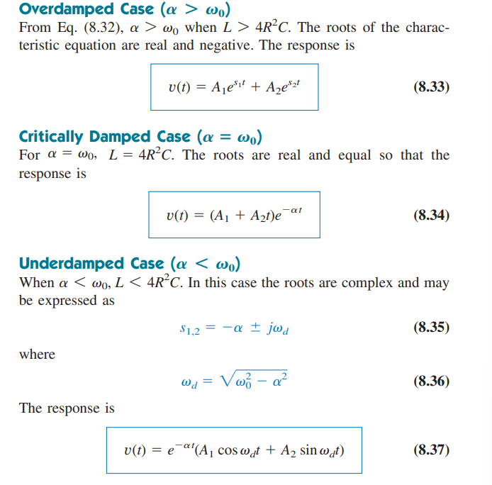
The Three Case Equations
Just as with before, each case (over dampening, critical dampening, under dampening) dictates a specific equation. Each case and each corresponding equation is the same as with a series RLC circuit.
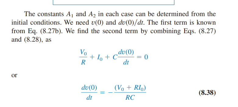
Auxiliary/Initial Equation Information
In order to solve for the coefficients of the response functions, we must (again) utilize v(0), I(0), and the differential term.
V(0)
The initial capacitor voltage assuming a steady-state condition.
I(0)
The initial inductor current during steady-state conditions.
Differential Term
dv(0)/dt = -(V(0) + RI(0))/(RC)