SysSig - Ch 10.1 to 10.5 - SteadyState power
1/32
There's no tags or description
Looks like no tags are added yet.
Name | Mastery | Learn | Test | Matching | Spaced | Call with Kai |
|---|
No analytics yet
Send a link to your students to track their progress
33 Terms
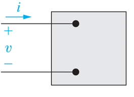
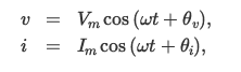
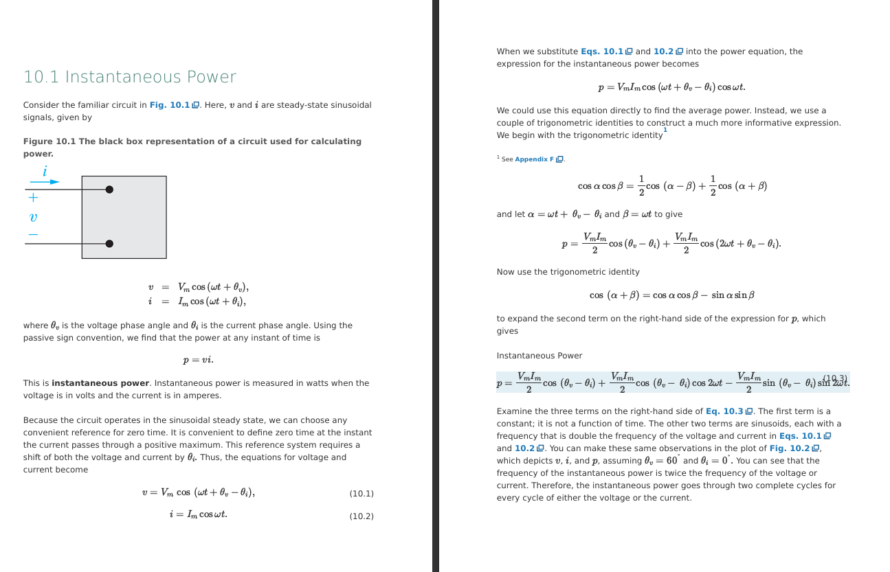
For this box, state equations for the steady state sinusoidal signals of v and i
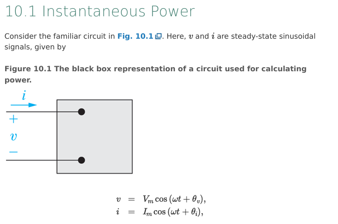
For this circuit and v , i equations, describe what is meant by instananous power
The power at any instant of time
p = vi
Use the steady state sinusoidal signals of v and i to derive the formula for power at any given instant of time

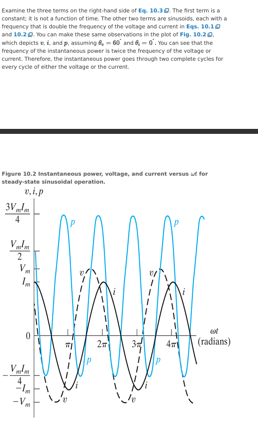
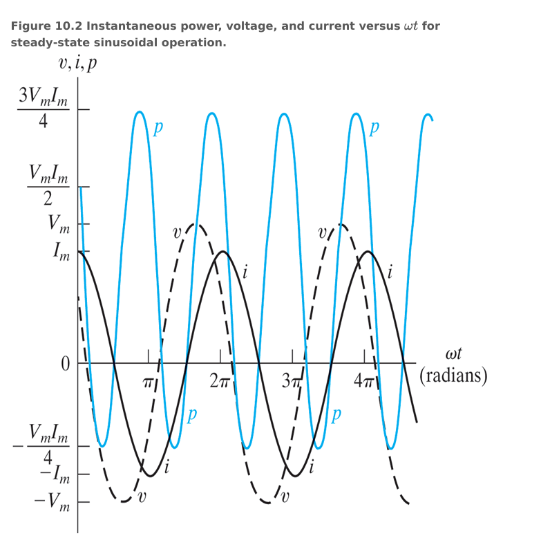
Describe the terms in the final instant power equation and show how it would look on a graph
For an instant power graph, describe what happens when p is negative
When it is negative the energy stored in inductors or capacitors is being extracted
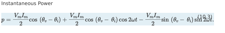
Rewrite the instant power equation in a simpler form.
State the identity of the terms
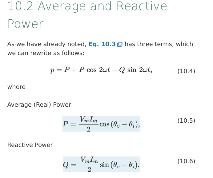
State what is meant by average/real power
power that is transformed from electric to nonelectric energy
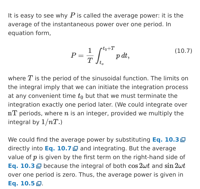
Describe why P is called average power by using integrals and stuff
Describe the instantanous power for purely resistive circuits
p = P + P cos (wt)
where P= avg power and w = angular freq
Also called instantaneous real power
power is never negative
power cannot be extracted from a purely resistive circuit
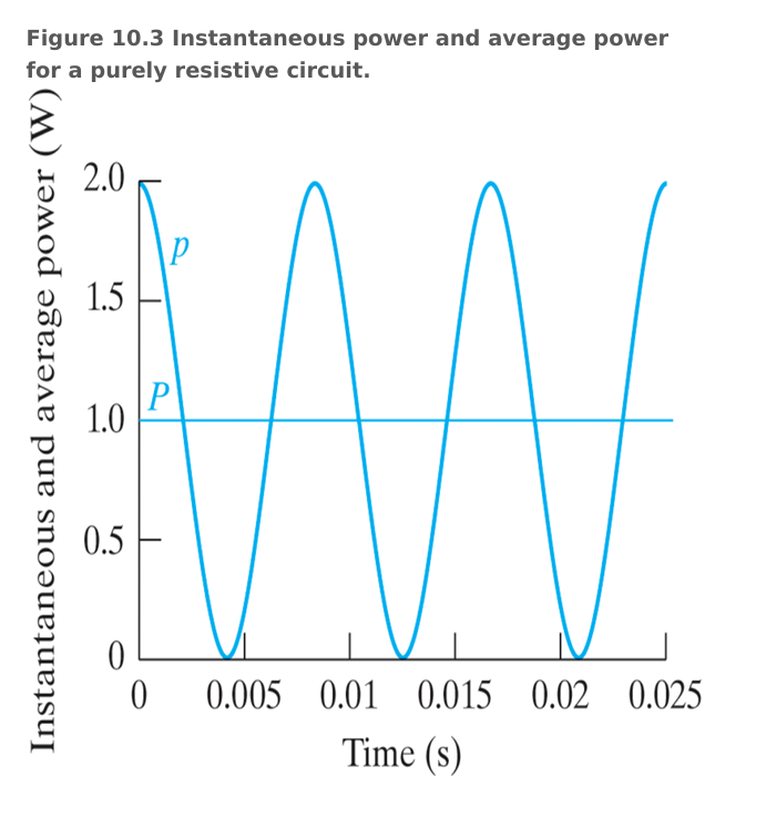
Show how a graph with w = 377, and P = 1 got a purely resistive circuit would look like
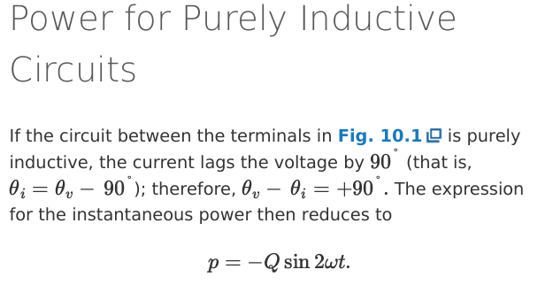
state the instant power expression in purely inductive circuits
for purely inductive circuits, current lags behind voltage by 90°
θi = θv - 90° and thus θv - θi = +90
thus instant power expression is p = -Qsin2wt
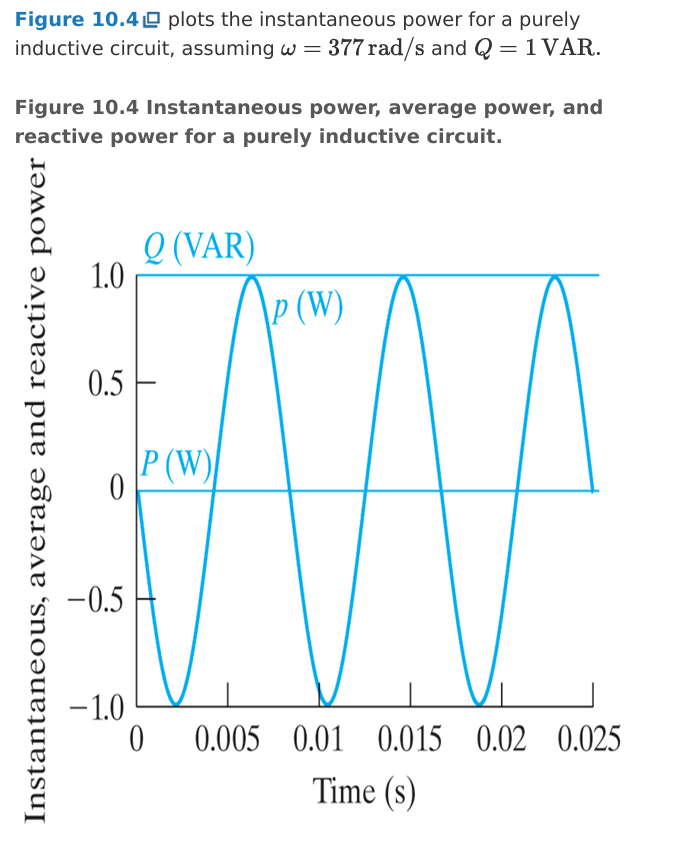
Describe the instant power expression for purely inductive circuits
avg power P = 0 (no energy converted from electric to nonelectric)
power is exchanged from circuit and source at frequency 2w
when p > 0, energy is stored in the inductive elements
when p < 0, energy is extracted from the inductive elements
State the units for average/real power and reactive power
units for P = watt
units for Q = volt-amp reactive/VAR
Describe how a graph of instant power for a purely inductive circuit would look like. Q = 1 VAR, w = 377
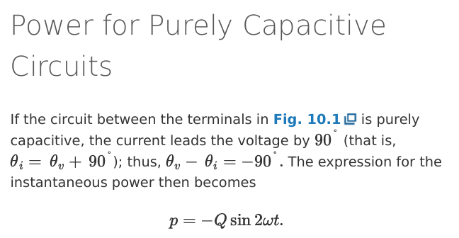
State the instant power expression for purely capacitive circuits
in purely capacitive circuits, current leads voltage by 90°
thus θi = θv + 90° or θv - θi = -90°
thus p = -Qsin 2wt
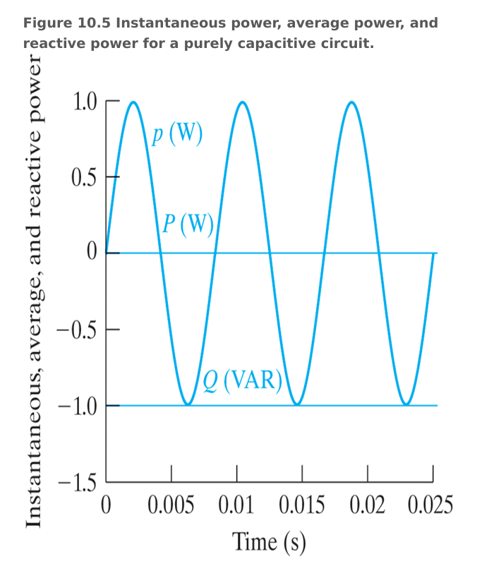
Describe the instant power expression for purely capacitive circuits and draw a graph where Q = -1 VAR and w = 377
P = 0 so no energy is converted from electric to non electric
power is exchanged from the source and capacitor
State when Q is positive or negative relative to inductors and capacitors
Q > 0 for inductors
Q < 0 for capacitors
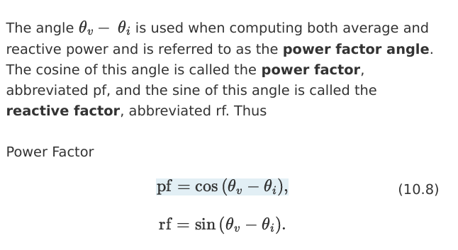
State what is meant by a:
power factor angle
power factor
reactive factor
power factor angle = θv - θi
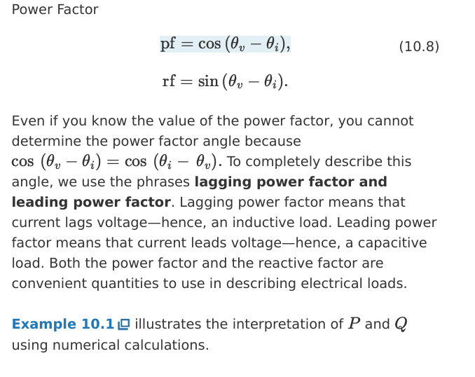
power factor = pf = cos (θv - θi)
reactive factor = rf = sin (θv - θi)
Describe what is meant by lagging and leading power factor
State why we us these terms
cos (θv - θi) = cos (θi - θv) so terms need to be used
lagging power factor means current lags voltage, so inductive
leading power factor means current leads voltage, so capacitive
Derive the average power of a sinusoidal voltage source delivered to a resistor in terms of Vrms and Irms
P = avg power, thus P = power through resistor over time
P = V²rms / R
P = I²rms * R
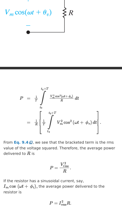
Describe the rms value of a sinusoidal voltage/current
The rms value delivers the same energy to R as a DC source of the same value
Referred to as the effective value
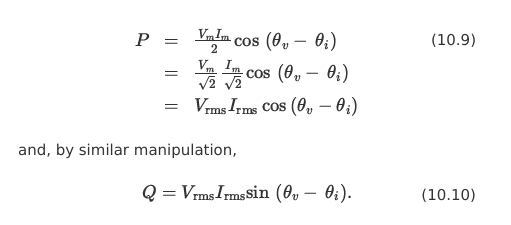
Rewrite avg power P and reactive power Q in terms of the rms values
P = Vrms* Irms*cos(θv - θi)
Q = Vrms * Irms * sin (θv - θi)
State the expression for complex power
S = P + jQ where:
S = complex power units are volt-amps
P = avg/real power units are watts
Q = reactive power units are var
Describe the complex power in relation the power triangle
|S| is the hypotenuse
P and Q are the sides of the triangle
θ is the angle between |S| and P
θ = θv - θi
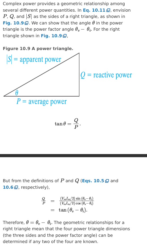
Describe what is meant by apparent power
modulus of complex power
|S| = sqrt ( P² + Q²)
represents the power transferred to components and the power produced by reactive components
Derive the phasor form expression of complex power S in terms of Vm, Im and in terms of Vrms, Irms
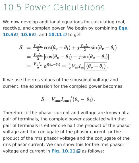
Derive the equations for the alternate form of the complex power in terms of the rms and amplitude values
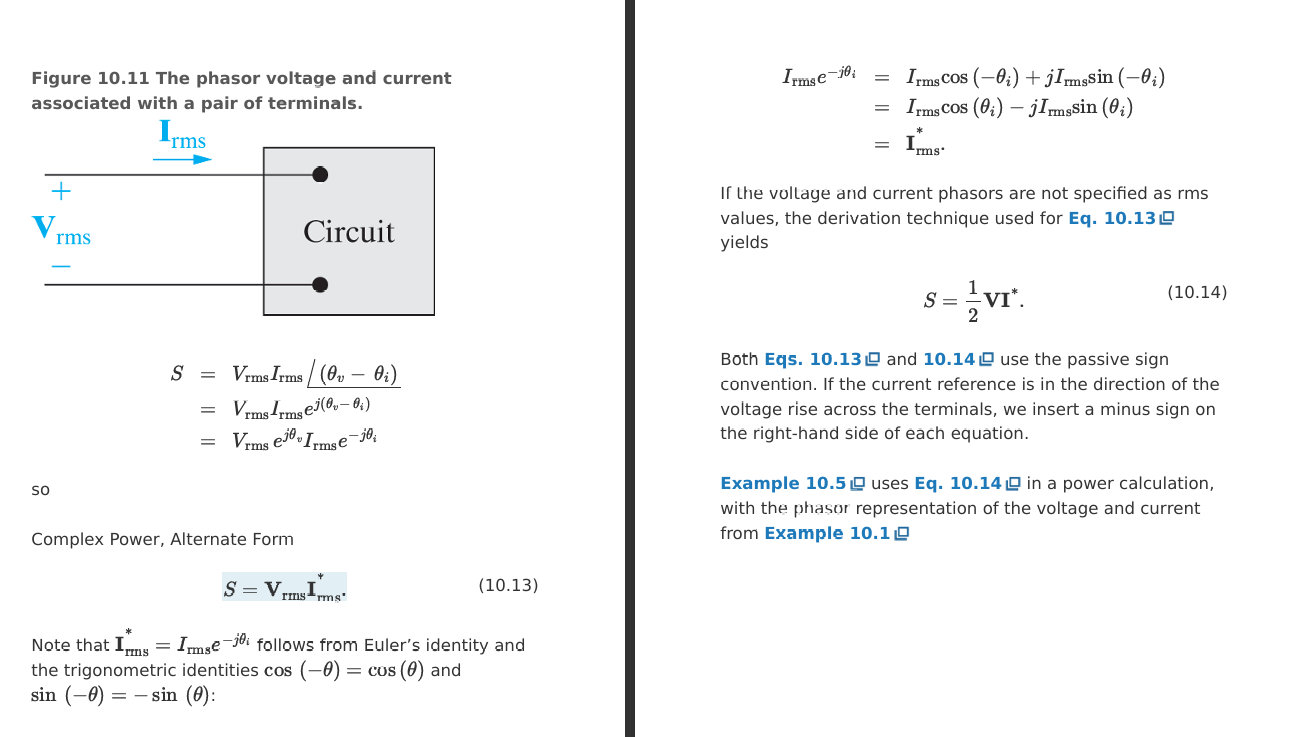
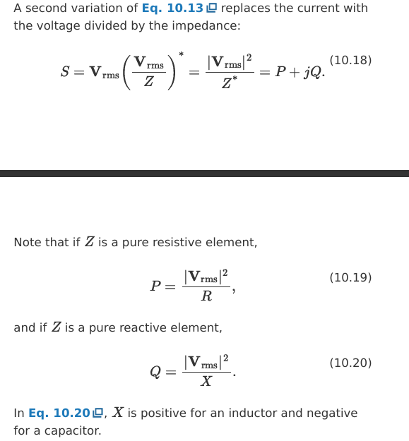
Derive the expression for complex power through an impeding component in phasor form where Vrms = Z * Irms
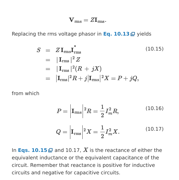
Derive the expression for complex power through an impeding component in phasor form where Irms = Vrms / Z
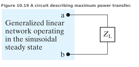
For this circuit derive the equations proving condition for achieving maximum average power transfer
I = Vth / (Zth + ZL)
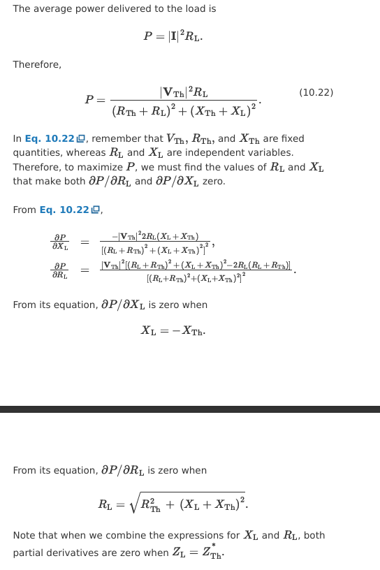
P = |I|² * RL
sub (1) into (2)
P is max when Xth = -XL
Derive P it is max when Rth = sqrt( Rth² + ( XL + Xth)² )
Thus P is max when:
ZL = Zth*
Derive the expression for Pmax when the conditions are met. In terms of Vrms and Vm
Vrms = Vm / sqrt(2)
I = V / Z
P = I² * RL

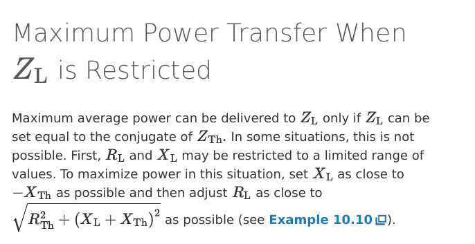
Describe how to acquire maximum power transfer to a load when XL and RL are limited
Set XL as close to -Xth as possible
Set RL as close to sqrt( Rth² + ( XL + Xth)² )
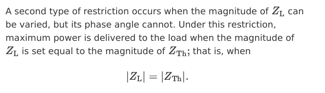
Describe how to get max P transferred to a load when the magnitude of ZL can be varied but its phase angle cannot
|ZL| = |Zth|