Capacitors and capacitance
1/24
There's no tags or description
Looks like no tags are added yet.
Name | Mastery | Learn | Test | Matching | Spaced | Call with Kai |
|---|
No analytics yet
Send a link to your students to track their progress
25 Terms
dielectric
insulatory material between two capacitor plates
voltage between plates
proportional to q (charge): v = (d/Ae) d
DC current
cannot flow through capacitor as there is an insulator between the two terminals
AC current
can flow through a capacitor as voltage across a capacitor is proportional to the charge on it. AC must correspond to alternating charge.
this gives the impression that an alternating current flows through capacitor
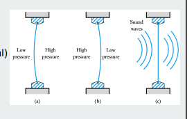
mechanical analogy of AC current through capacitor
Air (charge) cannot pass through a window in spite of the pressure difference (voltage potential)
However, alternating pressure can make the window vibrate, producing air movement
capacitor in parallel
voltage V is applied across two capacitors
Q = Q1 + Q2 —> C = C1+C2
capacitor in series
Q1 = Q2 = Q3, V = V1 + V2, 1/C = 1/C1+1/C2…
Exponential signal
RISE: signal reaches 63% at one time constant (tau), and 95% at 3 tau
FALL: signal reaches 37% at one time constant and 5% at 3 tau
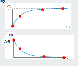
capacitor and exponential
as capacitor charges…
V(t), charging voltage, increases
V_R (voltage across resistor) decreases
I (t), charging current, decreases
results in exponential behaviout of I and V(t)
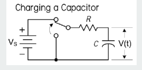
RC circuit and time constant
Charging current determined by R and voltage across it
Increasing R increases time taken to charge C
Increasing C increaes time taken to charge C as it can store more charge
Time required to charge to a particular voltage determined by CR
this is the time constant
step responses of an RC circuit
V(t) = Vs(1-e^(-t/RC))
Discharging capacitor in RC circuit
at t = 0, V(t) = Vs
via KVL first order differentials: V(t) = V2e^(-t/RC)
DC blocking
capacitor used to block DC voltage from passing to a part of the circuit
Capacitor filtering effect
circuits have different effects on the input signal at different frequencies
higher frequencies pass through capacitor with little to no reduction
signal gain (Vout/Vin)
Vout/Vin
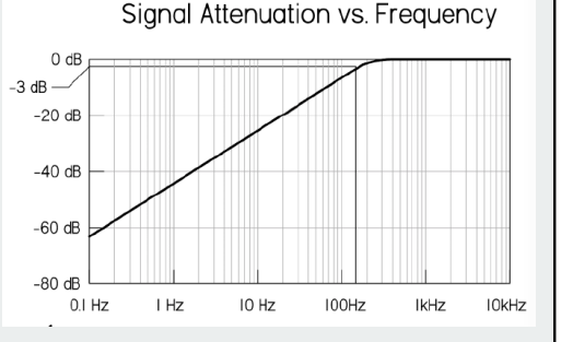
plot for filtering effect of Capacitor
if signal gain is plotted (Vout/Vin) against frequency, lower the gain and stronger suppression
0 frequency = -infinite gain (dB)
circuit can then block a DC signal
Logarithmic scale for both axes:
voltage gain
A = modulus of Vout/Vin (modulus of signal gain)
of lower than 1 (Vin is greater), this is the attenuation
decibels
unit of voltage gain
voltage gain log
20log10(vout/vin)
power gain (dB)
G = 10log (Pin/Pout)
why do we provide voltage and power gain ratios in log form
higher dynamic range
hearing and seeing sensitivity is logarithmic not linear
polystyrene capacitoy
two sheets of foil rolled up to save space with thin plastic film
ceramic capacitor
alternating layers of metal and ceramic
electrolytic capacitor
two sheets of aluminium foil separated by paper soaked in conducting electrolyte. The insulator is a thin oxide layer on one of the foils
polarised (oxide layer side must always be at positive voltage relative to other side)
negative side indicated by curved symbol
current/voltage continuity
voltage across capacitor never changes instantaneosly
it tries to keep its voltage constant
i = C dv/dt