SYSC3313 - Chapter 8 UML Diagrams
1/26
There's no tags or description
Looks like no tags are added yet.
Name | Mastery | Learn | Test | Matching | Spaced | Call with Kai |
|---|
No analytics yet
Send a link to your students to track their progress
27 Terms
UML (unified modelling language)
A standardize way to model structure and behaviour of software-based systems.
Multiple diagram types to describe different system aspects.
Behavioural diagrams
Focus on how a system reacts to events over time.
Ex: Activity diagrams, communication diagrams, timing diagrams, sequence diagrams, use-case diagrams, state machine diagrams, interaction diagrams
Structural diagrams
Describe the static organization of a system
Ex: class diagrams, components diagram, package diagram, deployment diagram, composite structure diagram
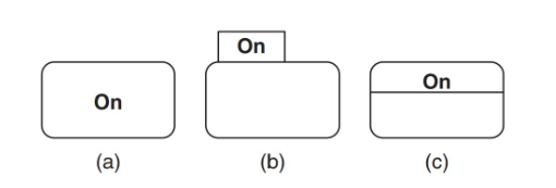
States in UML state diagrams
Represent a mode of operation.
Drawn as a rounded rectangle with state name show inside or in a tab.
Actions may be associated with entering the state, being is the state, or exiting the state. Called a dynamic state in that case.
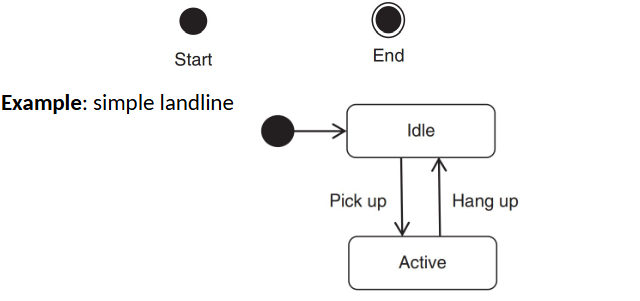
Initial and Final States in UML State Diagrams
Initial state is indicated using initial state marker
Final state is option. Indicated by final state marker
Types of States in UML State Diagrams
simple states
composite states
submachine states
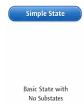
Simple State in UML State Diagram
Represents a basic situation with no sub states. Doesn’t have regions or submachine states like the others.
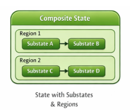
Composite States in UML State Diagrams
A more complex state that has substates organized into one or more regions.
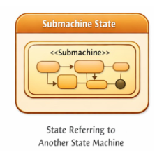
Submachine States in UML State Diagrams
Represents inclusion or reuse of another state machine’s specification. Allows inserting another state machine into a larger state machine.
D
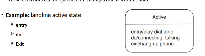
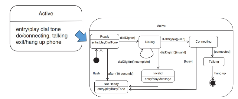
Dynamic States in UML State Diagrams
States may have actions associated with entering, being in, or exiting it.
entry: behaviour executed on entry
do: behaviour executed continuously while in the state
exit: behaviour executed when leaving the state
Place within a compartement in the state symbol. Use a / to separate action type and the action.
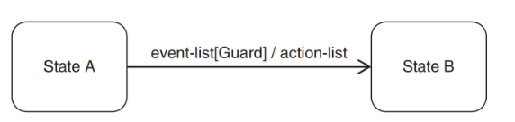
Transitions in UML State Diagrams
Represent changes from one state to another.
Possible labels:
event: an event or list of events to cause the transition
guards: a condition that is evaluated
actions: an operation executed when the transition is triggered
Active/Inactive States in UML State Diagram
The current state is the active state. When the state is exited, it becomes inactive. The target state is entered and it becomes the new active state.
Events in UML State Diagram
Events trigger transitions in a state machine. Events that trigger transitions depend on the current state (ie if the state doesn’t care about an event, nothing happens).
Event Types in UML State Diagrams
signal events: asynchronous event
call events: synchronous event
change events: occur when a condition is true
time events: occur after a specified duration or at a specified time
time-out: when a state is entered, a time-out begins, on expiry, an event is received. time-out is cancelled if the state is left. only one time-out per state.
Time event in UML State Diagrams
occur after a specified duration or at a specified time
Indicate duration using after(duration)
Indicate time using when(specified time)
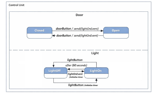
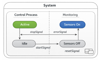
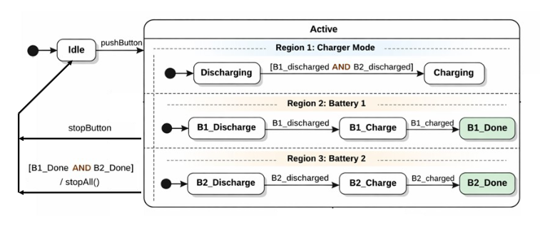
Orthogonality of Composite States
When the composite state includes two or more regions, they execute concurrently. Each region may have simple states, composite states, or submachine states.
Each region can be named.
Allows for parallel activities. (Improves modularity.)
Hierarchical states in UML state diagrams
Represents different levels of abstraction. By making a state into a composite state (with one region), you can expand on the details of that state.
Default entry state is indicated by start symbol. An end to the state can be indicated using the finish symbol.
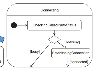
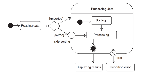
Choice Pseudostate in Hierarchical state in UML State Diagram
Represented by a diamond, it evaluates the guard conditions of outgoing transitions to select a valid path.
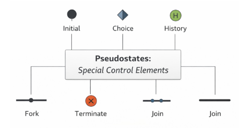
Pseudostates in UML State Diagrams
Special elements that control state machinie behavior.
Not real states but help define flow.
Ex: initial, choice, history, fork, join, terminate
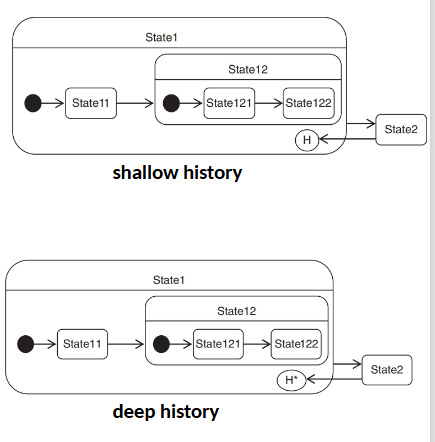
History pseudostate in UML State Diagrams
Allow composite states to resume from a point when last active.
The pseudostate must be explicitly pointed to. If there was no past entry, then enter at default state.
Two types:
shallow history: circled h, remembers the most recent active direct substate of a composite or submachine state
deep history: circle h with asterisk, if there are more composite states, it will remember even the nested substate it was in.
Entry/exit point pseudostates in UML State diagrams
If you want to enter any state besides the default or last active state (history), you can define a named entry location in the composite state.
Similarly you can have alternative exit points.
Place the symbol on the border of the composite state.
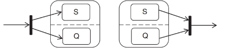
Fork and Join pseudostates in UML State diagrams
Fork pseudostate splits a transition into two or more transitions terminating in target states in different orthogonal regions of a composite state. Cannot have guards or triggers.
Join pseudostate merges transitions to source states in different orthogonal regions of a composite state..
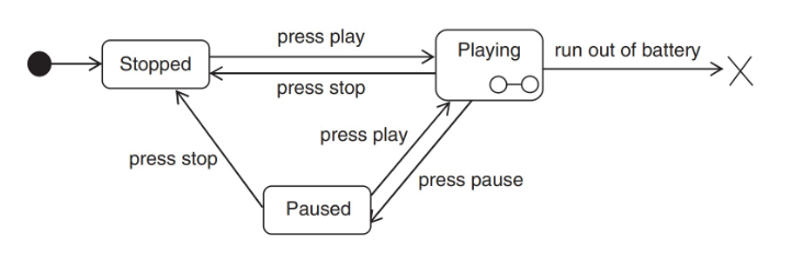
Terminate Pseudostates in UML State diagrams
Represents termination of a state machine. The system stops responding when termination is reached.
Models abnormal shutdowns. Indicates irreversible termination.
Represented by x
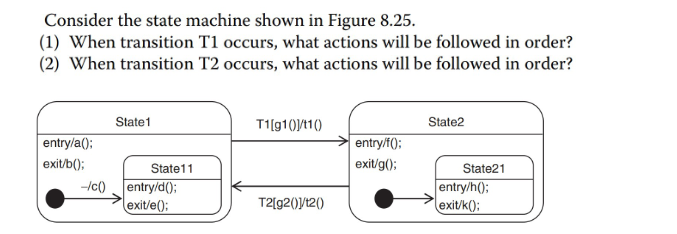
Problem 1
T1 order: e(), b(), t1(), f(), h()
T2 order: k(), g(), t2(), a(), c(), d()
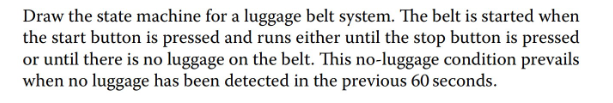
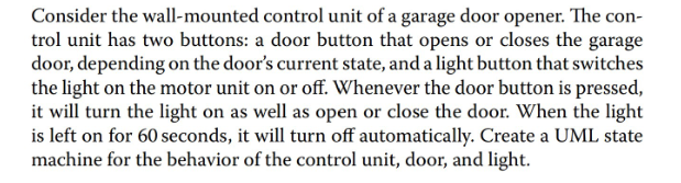
Problem 2
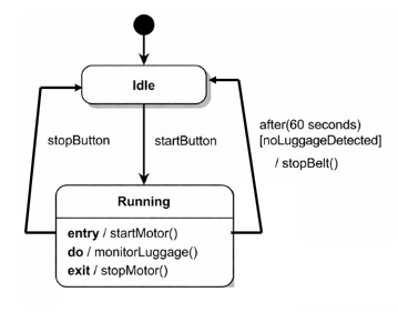
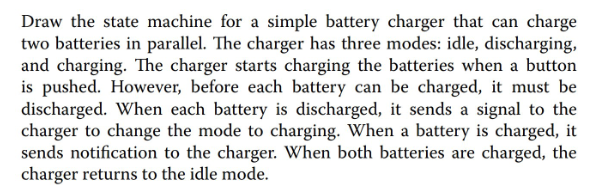
Problem 3
Problem 4