VL V - MEX and BJT
1/54
There's no tags or description
Looks like no tags are added yet.
Name | Mastery | Learn | Test | Matching | Spaced | Call with Kai |
|---|
No analytics yet
Send a link to your students to track their progress
55 Terms
Pros MEX
Easy to use
Equipment usually not expensive
Great variety of materials
Small to large parts printable
Multi material parts
Cons MEX with highly filled Polymers
High surface roughness compared to other AM techniques
Anisotropy of properties
Support structure
Accuracy and speed can be low
feeding MEX
Plunger based
Filament based
Screw based
Parts of MEX
Build Platform
Built part
Build material
Extrusion head
Build or support material
How can the Process for MEX be split
Additive Manufacturing process
secondary process
Whats part of the AM process MEX and happens inbetween
Feedstock material
heating
Fusion melting
Control
Extrusion
cooling
Solidification
Whats part of the secondary Process MEX + inbetween
Green part/body
Furncace sintering
Consolidation
Whats the composite material made out of
Binder system
Filler(s)
What does the polymeric component consist of
Main binder component (50-90% V)
Backbone (0-50% V)
Additives (0-10%)
Different types of fillers MEX
Ceramic fillers
Metal fillers
Ceramic fillers
SIlicon nitrate
Fused silica
Zirconia
Strontium ferrite
Tatanium dioxide
Metal fillers
Stainless steel
Titanium
Tungsten carbide-cobalt
Rare earth magnet
What do filler characteristics influence
Mechanical and flow properties
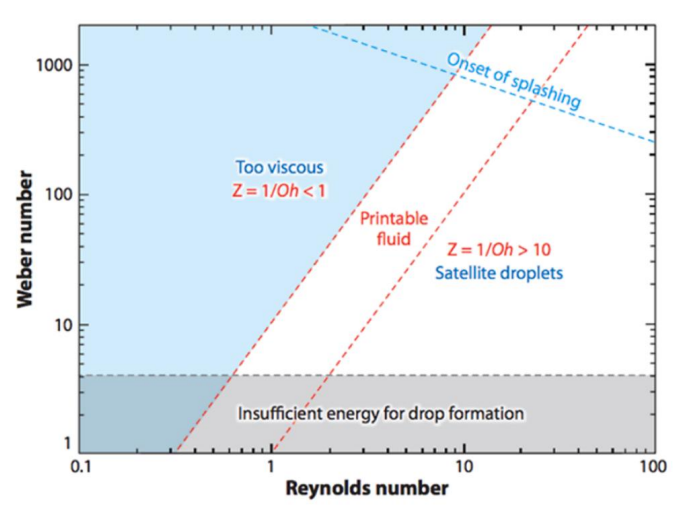
Which characteristics Materials or Filaments are not printable (MEX Filler)
Filaments with low mechanic properties
Materials with high melt viscosity
What are influencing factors on Filler properties
Different particle size
Morphology
Chemical composition
What do the processability of filaments depent on
Mechanical properties of filament
flow properties of feedstock
processing conditions
geometry of the filament
design of printing head
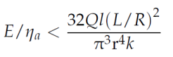
When does Buckling occur
When extrusion pressure exceeds critical buckling stress
Processing parameters MEX
Build orientation
Bead width
Layer/slice thickness
Contouring
Raster orientation
Air gap
Nozzle or liquefier temp
Envelope temp
Feed rate
Extrusion rate
Travel speed
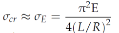
Critical buckling stress formula
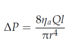
Pressure drop in the nozzle
Buckling when formula
Path generation MEX
Destinction between contours and infill area
infill between contours
Different path strategies for contour and infill
Whats debinding MEX
Describes removal of the polymeric binder system
Which critical defects can occur during debinding
Bloating
Blistering
Surface cracking
Emergence of large internal voids
Three main debinding techniques
Thermal (most common)
Solvent
Catalytic
Why does the binder system has to be removed
Since carbon residues can influence sintering process negatively
Sintering properties MEX
Thermal treatment that metallic powders into bulk material
Sintering performed at below melting point (70-90% of melt temp)
What happens during sintering MEX
Growth of sinter necks between particles
reduction of porosity
shrinkage of part and densification
Whats BJT
Liquid binder is deposited on powder materials to bond them together
Pros BJT
High porductivity
Wide range of materials availible
Huge parts are printable
Shaping occurs at room temp
Various densities with controlled porosity
High design freedom
no support structures
Cons BJT
Properties dependent on binder used
Post processing is needed
Powders can be harmful
Slightly rough surface
Process steps BJT
Material preparation
Printing
Curing
Debinding
Sintering
Feedstock material properties
In principle, any powder can be processed
Ratio of material to binder is different for each powder
Ratio approx. 80:20 for plastic and approx 60:40 for sand
Whats the feedstock made of
Powder and Binder
Material Powder BJT
Sand
Plastic
Ceramic
Metal
Material Binder BJT
Water + glycerol
Solvent
Liquid
Requirements of the binder
Rheology for inflitration and printing
Stability to be deposited
Wetting the powder and proper penetration
Enough binding strength to provide structural integrity
Thermal characteristics
What are the three types of binders availible BJT
Acid based binder
Metals salts binder
Aqueous based binder
Rheology of Printing Diagramm
Possible Interaction between binder and powder bed
Initial contact
Spreading
Drainage
Saturation
How is the spreading parameter S calculated
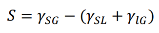
What can be said over the size of S
When S > 0 complete wetting
When S < 0 partial wetting
Measures to enhance wetting behavior
Increase of surface tension of the solid
Decreasee of the surface tension of the liquid
How can the infiltration or drainige be calculated
Via the Washburn equation (assuming radial symmetry of the liquid and porosity, neglecting finite size pore)
What influences Infiltration BJT
increases with particle size
Nano particle decrease inflitration speed
Properties of sintered part improve
What process parameters influence printing in BJT
Layer thickness
Powder spread and print speed
Saturation level
Feed to powder ratio
Part orientation
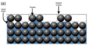
What is Binder Saturation
Volume fraction of binder in the voids
What does binder saturation influence
Dimensional and geometric accuracy
Surface quality
Whats Undersaturation (Binder BJT)
Inadequate binder saturation
Powder can drop from green part
Poor surface finish and dimensional accuracy
Whats oversaturation
Binder saturation too high
Migrate to outside the defined area
Poor surface finish and dimensional accuracy
Post processing steps
Curing cycle
Depowdering
Burn out/Debinding
Infiltration
Sintering
What Phenomenon can be seen in this picture
Undersaturation
What Phenomenon can be seen in this picture
Oversaturation
Sag effect Sintering
Occurs because unsuppurted material gets close to melting point
Drag effect
Arises from friction between shrinking part and ceramic plate of furnace plate on which it rests during sintering