H2: Shading & Illumination
1/31
There's no tags or description
Looks like no tags are added yet.
Name | Mastery | Learn | Test | Matching | Spaced | Call with Kai |
|---|
No analytics yet
Send a link to your students to track their progress
32 Terms
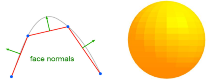
why we need shading
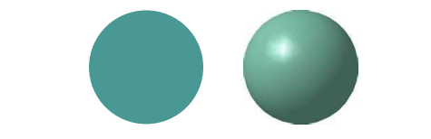
If we color our 3D computer graphics models with uniform color, they will appear flat.
Shading is needed to give the 3D impression.
Suppose we build a model of a sphere using many polygons and color each of these polygons with the same flat color. The result (left) appears as a flat circular region. The image on the right is obtained with appropriate shading.
Shading for realistic rendering
To achieve realistic appearance of the generated 3D objects, start from a physical perspective: why do the objects appear shaded in reality?
What is the interaction between light and matter?
Need to consider:
Type of light sources
Type of surface (material properties)
Surface orientation
Relative position of the viewer
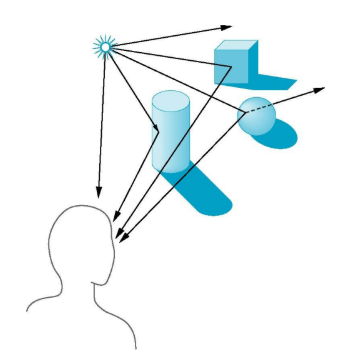
Interaction between light and surfaces
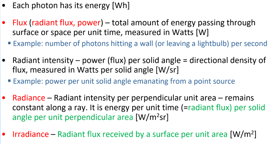
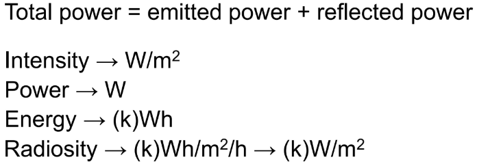
Basic definitions
flux
radiant intensity
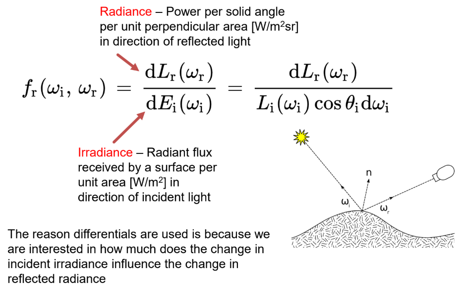
Radiance
Irradiance
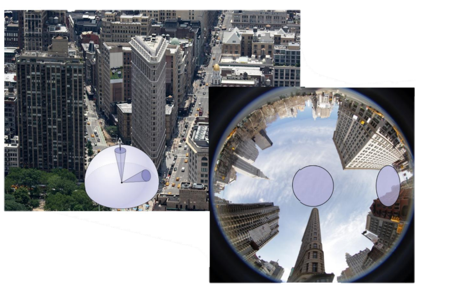
Unit solid angle:
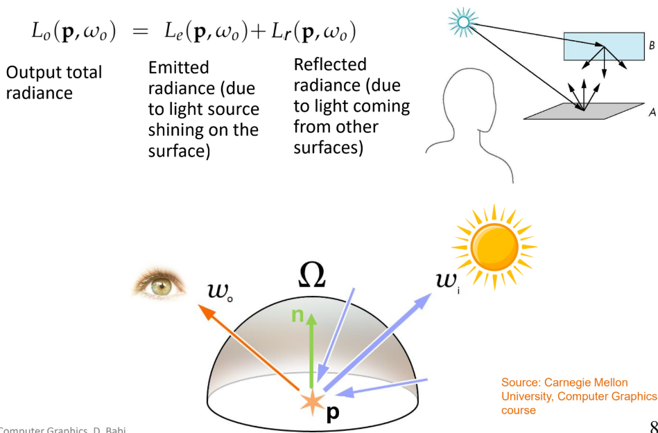
Rendering equation (figuur)
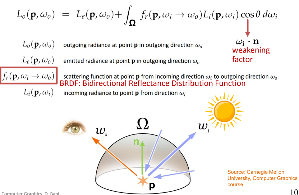
Bidirectional Reflectance Distribution Function
BRDF vs BTDF vs BSDF

Light sources
Ambient light
Point source
Spotlight
Distant sources
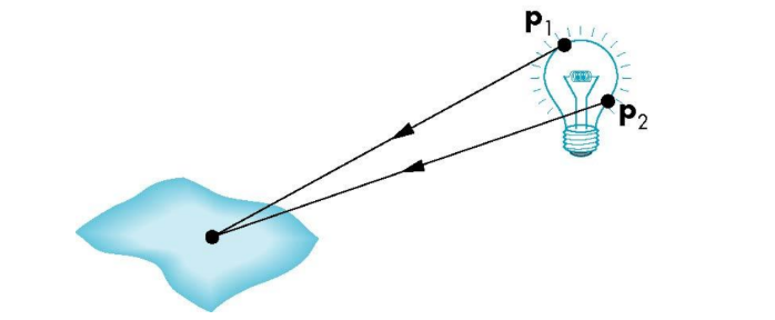
General light sources are difficult to work with because we must integrate light coming from all points on the source.
Ambient light
Same amount of light everywhere in scene
Models contribution of many sources and reflecting surfaces
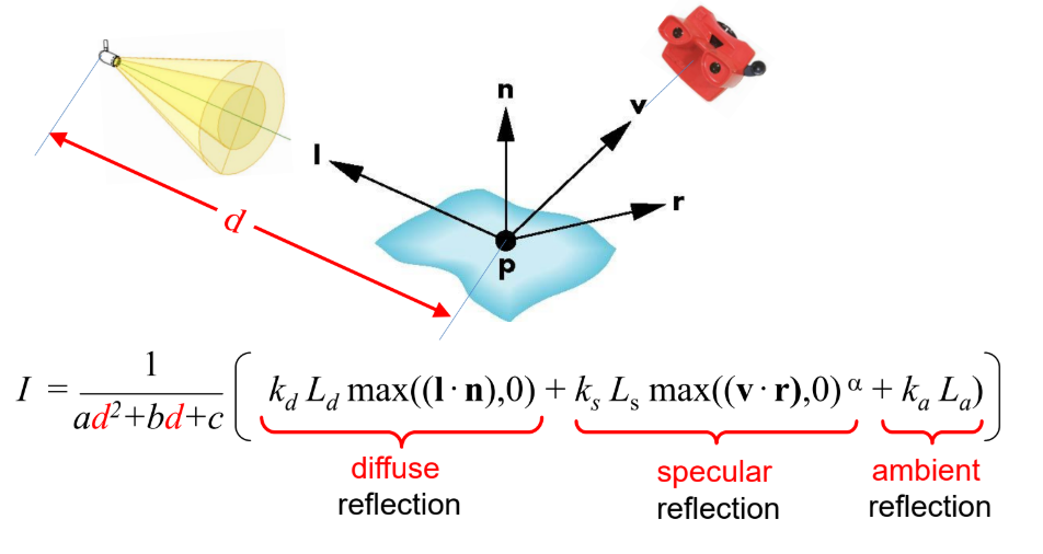
Point source
Light emitted equally in all directions
The intensity of illumination proportional to the inverse of the square of the distance between the source and the surface
Easy to use, not highly realistic
Scenes rendered with point sources tend to have high contrast
Spotlight
Restrict light from ideal point source
Distant sources
Object is illuminated with parallel rays of light
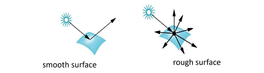
Surface types
The smoother a surface, the more reflected light is concentrated in the direction a perfect mirror would reflect the light.
A very rough surface scatters light in all directions.
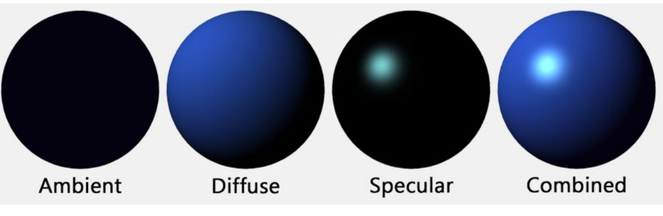
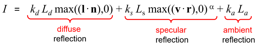
Phong model
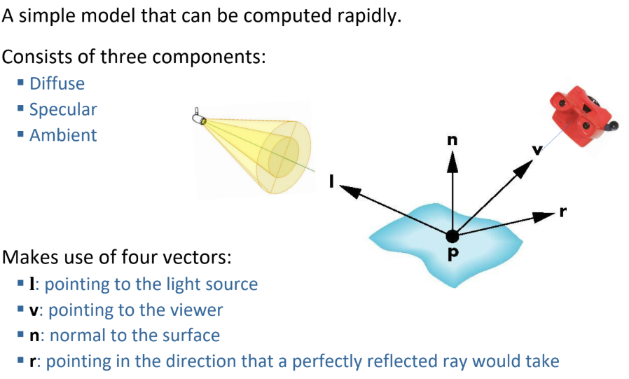
Material - light interactions in the Phong model
(3 soorten)
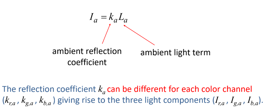
Ambient reflection
The intensity of ambient light is the same at every point in the surface
Some of this light is absorbed, some is reflected
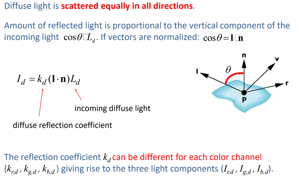
Diffuse reflection
The reflected light is scattered equally in all directions – rough surfaces
The amount of the light reflected depends on the
material properties,
position of the light source relative to the surface
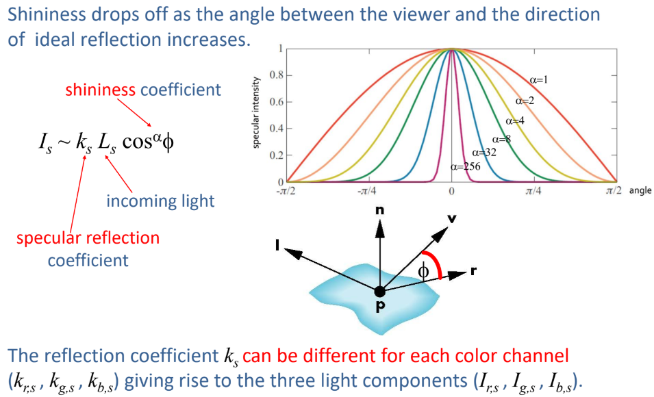
Specular reflection
Smooth surface appears shiny
Gives highlights (without this reflection, the surface appears dull)
The amount of the light reflected depends on the position of the viewer and direction of reflected light
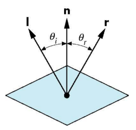
Ideal reflector and ideal diffuser
Ideal reflector
Normal is determined by local orientation
Angle of incidence = angle of reflection
The three vectors must be coplanar
Lambertian surface
Perfectly diffuse reflector
Light scattered equally in all directions
Amount of light reflected is proportional to the vertical component of incoming light
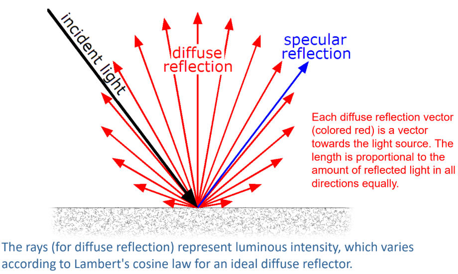
Specular Surfaces
Most surfaces are neither ideal diffusers nor perfectly specular (ideal reflectors).
Smooth surfaces show specular highlights due to incoming light being reflected in directions concentrated close to the direction of a perfect reflection.

Light sources in the Phong model
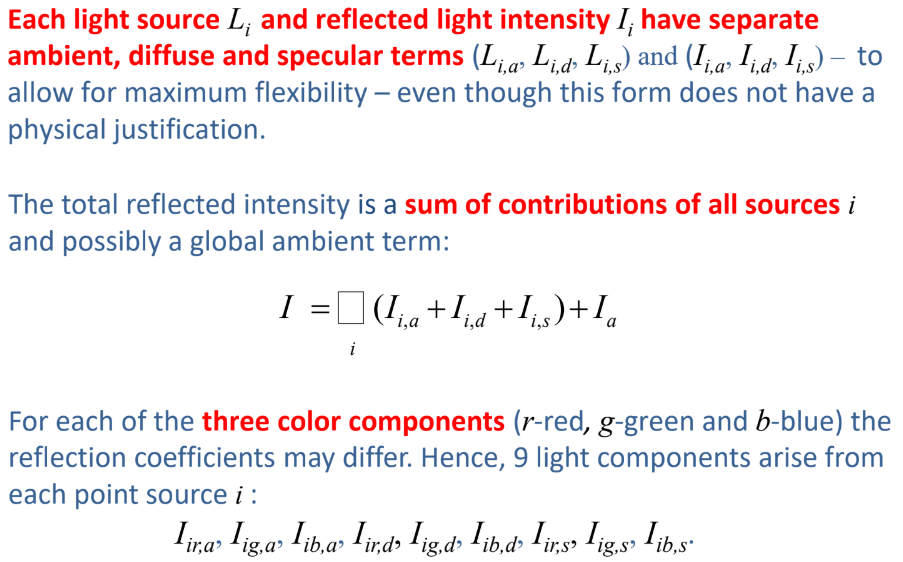
Modeling ambient refelctions
Ambient light is the result of multiple interactions between (large) light sources and the objects in the environment.
Amount and color of the reflected light depends on both the color of the light source(s) and the material properties of the object.
Modeling diffuse relfections
Modeling Specular reflections
Adding up the components
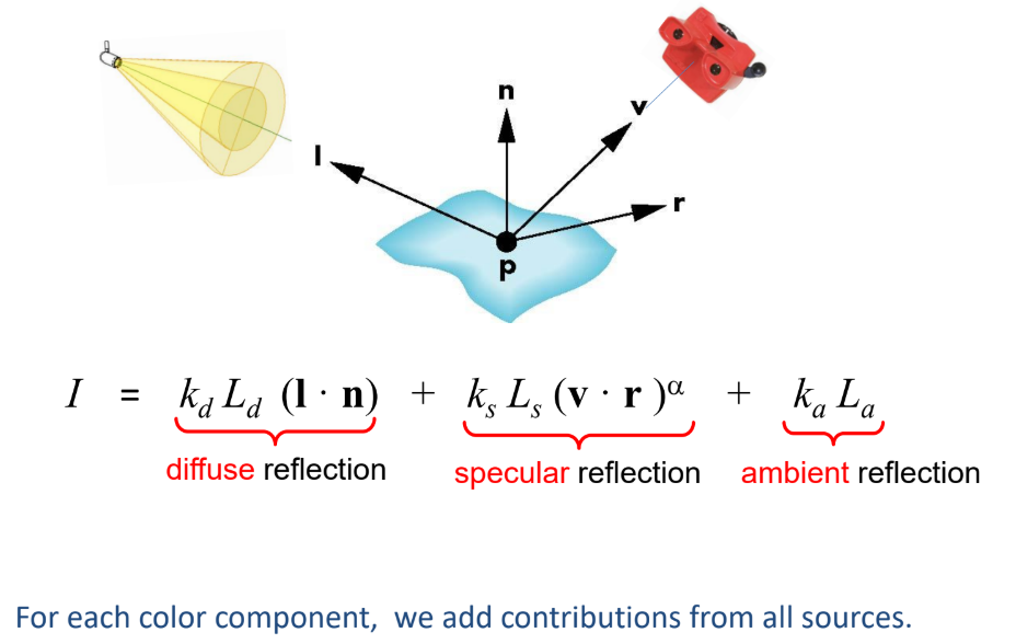
Practical calculation:
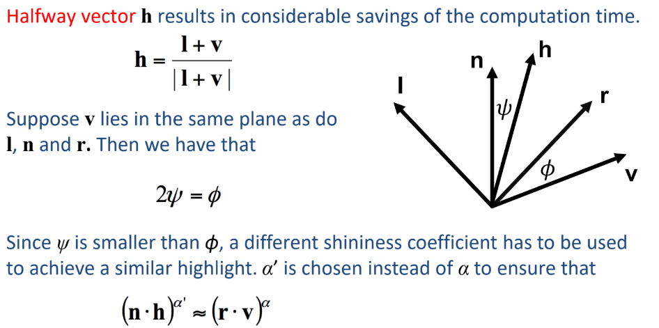
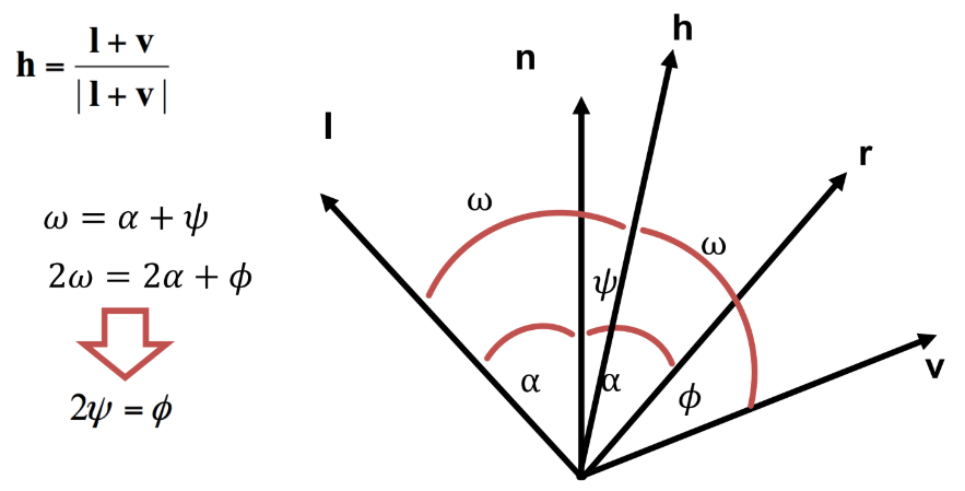
Blinn-Phong model
The modified Phong model (Blinn-Phong model) applies an approximation to avoid recalculating the dot product v . r at each point of the surface (calculating r is expensive).
Polygon shading
Idea: a smooth surface can be represented by a polygonal mesh with a normal at each vertex.
Think – this seems incorrect - how to assign a normal to a vertex?
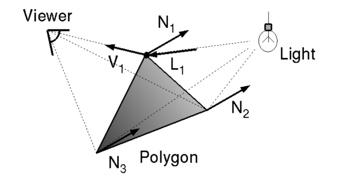
Flat shading
For each face, a single (usually first) normal is used.
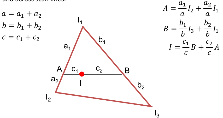
Gouraud shading
One lighting calculation per vertex:
Assign colors to pixels inside the polygon by interpolating colors computed at vertices.
Actual implementation:
bilinearly interpolate colors at vertices down and across scan lines.
How much is A in terms of I1 and I2 and distances a1 and a2? Think of extremes with these kind of problems
Phong shading
One lighting calculation per pixel:
Approximate surface normals for points inside polygons by bilinear interpolation of normals from vertices.
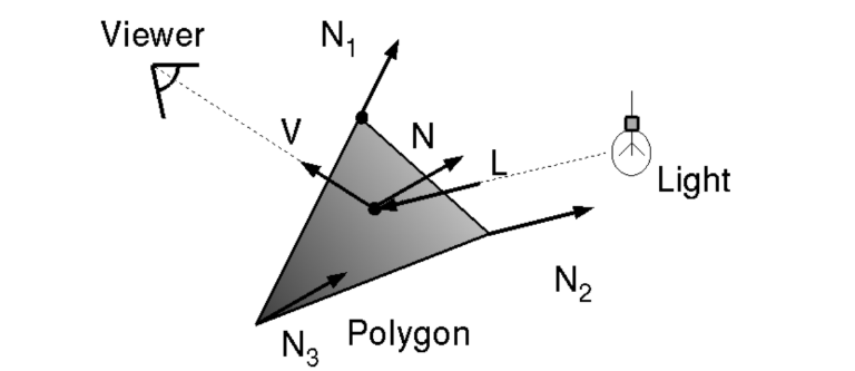
Actual implementation:
bilinearly interpolate surface normals at vertices down and across scan lines.
Ray tracing
Idea: follow rays of light from a point source to account for reflection and transmission.
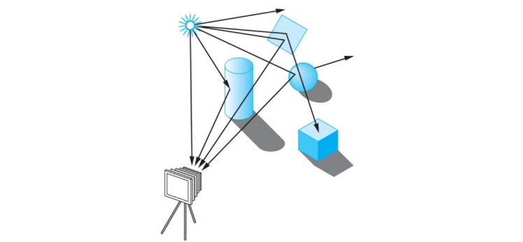
Note: most rays do not affect what we see. Scattering produces many additional rays, most of which are also irrelevant for what we see.
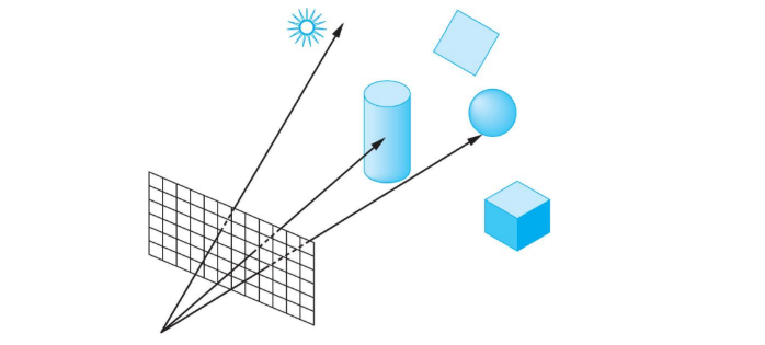
Alternative: ray casting.
Ray casting
Idea: reverse the direction of rays to follow only those that reach the center of projection.
At least one ray is needed per pixel.
Shadow rays & following shadow rays
Even if a point is visible, it will not be lit unless we can see a light source from that point.
Cast shadow or feeler rays.
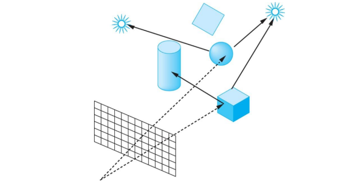
Follow shadow rays of reflecting or transmitting surfaces to determine the color of each point in the surface.
This is a recursive process.
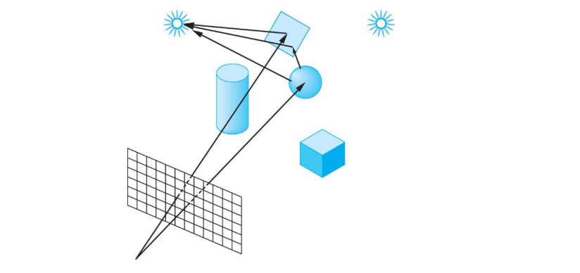
Reflection and transmission
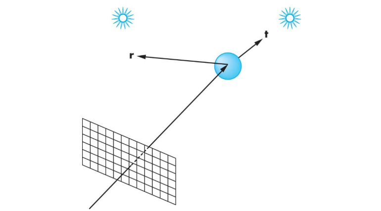
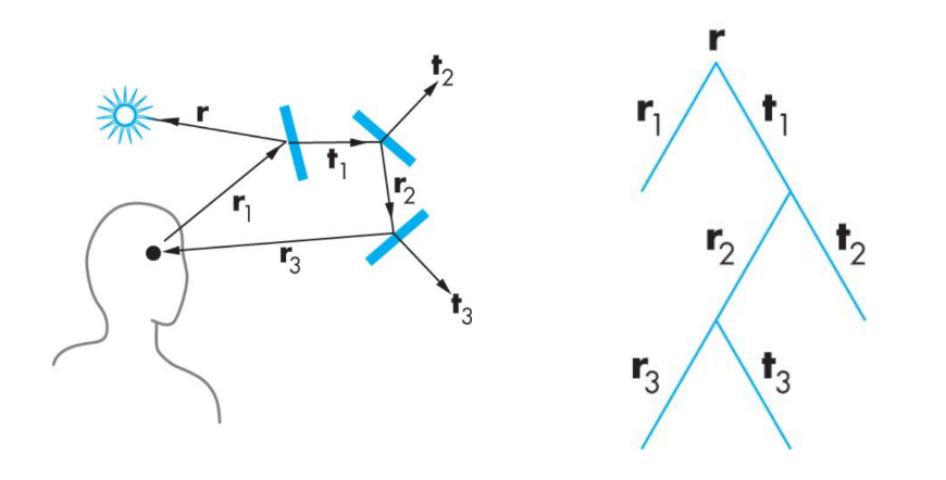
Ray trees
A simple ray-traced environment and the generated ray-tree
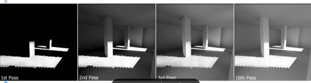
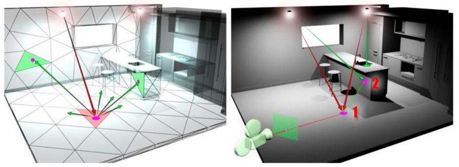
Advanced rendering: Radiosity
Ray tracing works best with many highly specular surfaces – not characteristic of real scenes
How to create image with “soft” shadows?
Why do we need radiosity?
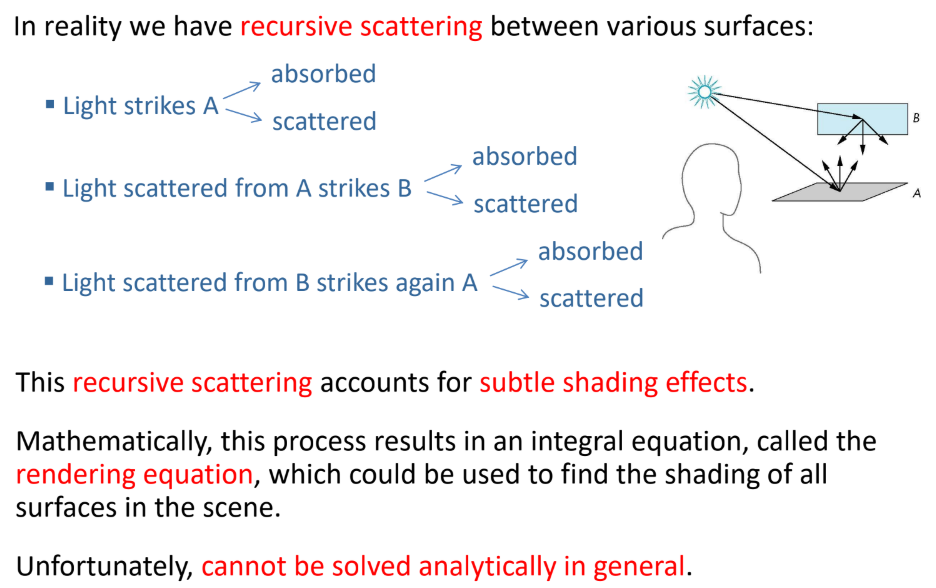
Rendering equation describes the general shading problem but is difficult (if at all possible) to solve in practice.
Radiosity solves the rendering equation for perfectly diffuse surfaces.
Objects are broken up into flat patches (which may correspond to the polygons in the model) that are perfectly diffuse reflectors
Radiosity: what
Consider objects to be broken up into flat patches (which may correspond to the polygons in the model) that are perfectly diffuse reflectors
Radiosity = flux = intensity = energy/unit area/unit time leaving patch = light power (energy/unit time) per unit area leaving the patch
Radiosity Equation: iterative calculation
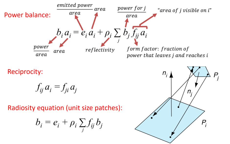
Solution: iteratively apply the single-bounce update formula.
this is essentialy how we solve the BRDF from the beginning