Fluoroscopy + CCDs
1/29
Earn XP
Description and Tags
carter ch. 6 + bushong 19&20
Name | Mastery | Learn | Test | Matching | Spaced | Call with Kai |
|---|
No analytics yet
Send a link to your students to track their progress
30 Terms
CCD’s + sequence
Oldest indirect conversion
SEQUENCE:
X-ray interact with scintillation material
Sent to capacitors which convert light into electrical charge
Charge sent to ADC
Structure - silicon chip
Cesium Iodide-structured phosphor (similar to a TFT) reducing light spread
how its coupled→Lenses or fiber optics focus light onto chip - beam splitting mirror
Used in fluoro, C-arms for trauma or forensic and stereotactic breast biopsy
CMOS
Complementary metal oxide semiconductor
Highly efficient and inexpensive
More susceptible to noise so lower quality, lower resolution and lower sensitivity as compared to CCD’s
Convert light into electrons-stored in capacitors within the pixel then to ADC
Binning
Just remember → Binning allows charges from adjacent pixels to be combined on the sensor before the charge is readout through the amplifier, the dominant noise source on a CCD.
-Faster way to get a readout (grocery example = stuffing groceries in 2 bags when it actually 3 bags worth of food)
-combine pixels together to improve image quality
-Part of CCD
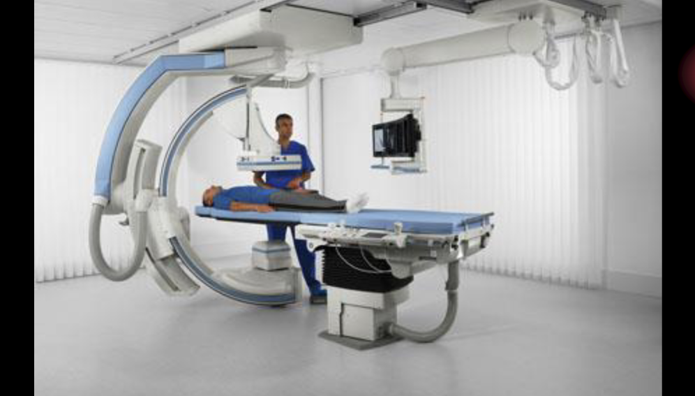
Flat panel Fluoro
HISTORY
• Thomas Edison, 1896
• Screen placed over patient’s body in x-ray
beam
• Radiologist looked directly at screen
• Red goggles-30 minutes before exam - night vision
• 1950 image intensifiers developed - intensifying the light of the image
Cones
Central
Less sensitive to low light (threshold of 100 lux)
Will respond to bright light
Daylight vision (phototopic vision)
Perceive color, differences in brightness
Perceive fine detail
WE WANT CONES
Rods
Periphery
Sensitive to low light
Used in night vision (scotopic vision)
Dims objects seen better peripherally
Color blind
Do not perceive detail
Dont want to use rods, want to use cones
Fluoro xray tubes
Under the table
Operate at less than 5 mA, so low because the long exposure time w/ higher kvp so mA has to be lower for correct mass
KVP dependent on body section
ABC (Automatic brightness control) = ABS (Automatic brightness stabilizer) = AGC (Automatic gain control) → Maintaining the brightness by changing technical factors automatically
AERC - Automatic exposure radiation control (using an AEC-controls the time)
Fixed xray tube - How far from the patient?
No closer than 15 inches or 38 cm from the patient, under the table
Carm Mobile - How far from the patient?
May be brought no closer than 12 inches or 30 cm from patient
Which has less radiation Over-couch or under couch?
Under the couch
The Sequence
Beam exits the patient - remnent
Hits the input phosphore(cesium iodide CsI tightly packed needles… produce excellent spatial resolution)
Converts x-rays to visible light
Hits photocathode (Cesium and antimony components)
Emits electrons when struck by light (photoemission)
The potential difference within the image intensifier tube is a constant 25,000 volts
Electrons are accelerated to anode → Anode is a circular plate with hole for electrons to go through → Focusing lenses=electrostatic lenses
Hits output phosphor which interact with electrons and produce light
Electrons hit output phosphor (zinc cadmium sulfide) with high kinetic energy producing an increased amount of light
The electron path
Must be focused for accurate image pattern → use electrostatic lenses (focusing devices)
Accelerate and focus electron beam
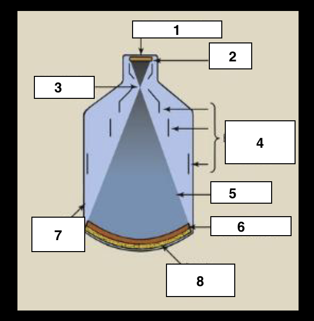
Label
Output phosphor
Anode
Focal point
Electrostatic lenses
electrons
Photocathode
Glass envelope
Input Phosphor
What happens after light is emitted from output?
Old school → Was transmitted as an analog signal via a TV tube called Plumbicon/vidicon
Now→ light is captured by a CCD or a FLAT PANEL SYSTEM is
used
Flux gain
1 xray = ? light photons
Comparing the # of x-rays coming in and the # light photons coming out
1 xray = 3000 light photons
-Want a bright image = larger diameter
-smaller diameter = lower brightness → direct relationship
# of output light photon / # of input x-ray photons
Minification gain
Ratio of the square of the diameter of the input phosphor to the square of the diameter of the output phosphor OR
Comparing a change of activated diameter of the input phosphor to the fixed diameter of the output phosphor
-Larger diameter = more minification gain
-Minification goes down = brightness gain goes down
Brightness gain
Flux gain x minification gain
-Ratio of the intensity of the illumination ot the output phosphor to the radiation intensity at the input phosphor
-Brightness gain of 5000-30,000
-Maintaining (automatic) of the brightness is called ABC or ABS or AGC (control,stabilization gain control) or AERC-Automatic Exposure Radiation control- Adjust MA and make more patient exposure
Conversion factor
Ratio of intensity of illumination at the output phosphor (measured in Candela per meter squared) to the radiation intensity at the input phosphor (mGya per sec)
(Cd/m2 ) / (mGya/s)
→ miligray coming in and candela coming out
MULTIFIELD IMAGE INTENSIFICATION
Allows focal point change to reduce field of view and magnify the image
-Multifield is different diameters
-Standard component on most machines
-Always built in in digital units
-Most popular is 25/17/12 → 12 on input phosphor = has the least flux gain
-Trifield tubes are 25/17/12 or 23/15/10
At 25 - all photoelectrons are accelerated to output phosphor
MULTIFIELD IMAGE INTENSIFICATION
25 diameter - all photoelectrons are accelerated to output phosphor
17 diameter
12 diameter - more magnification
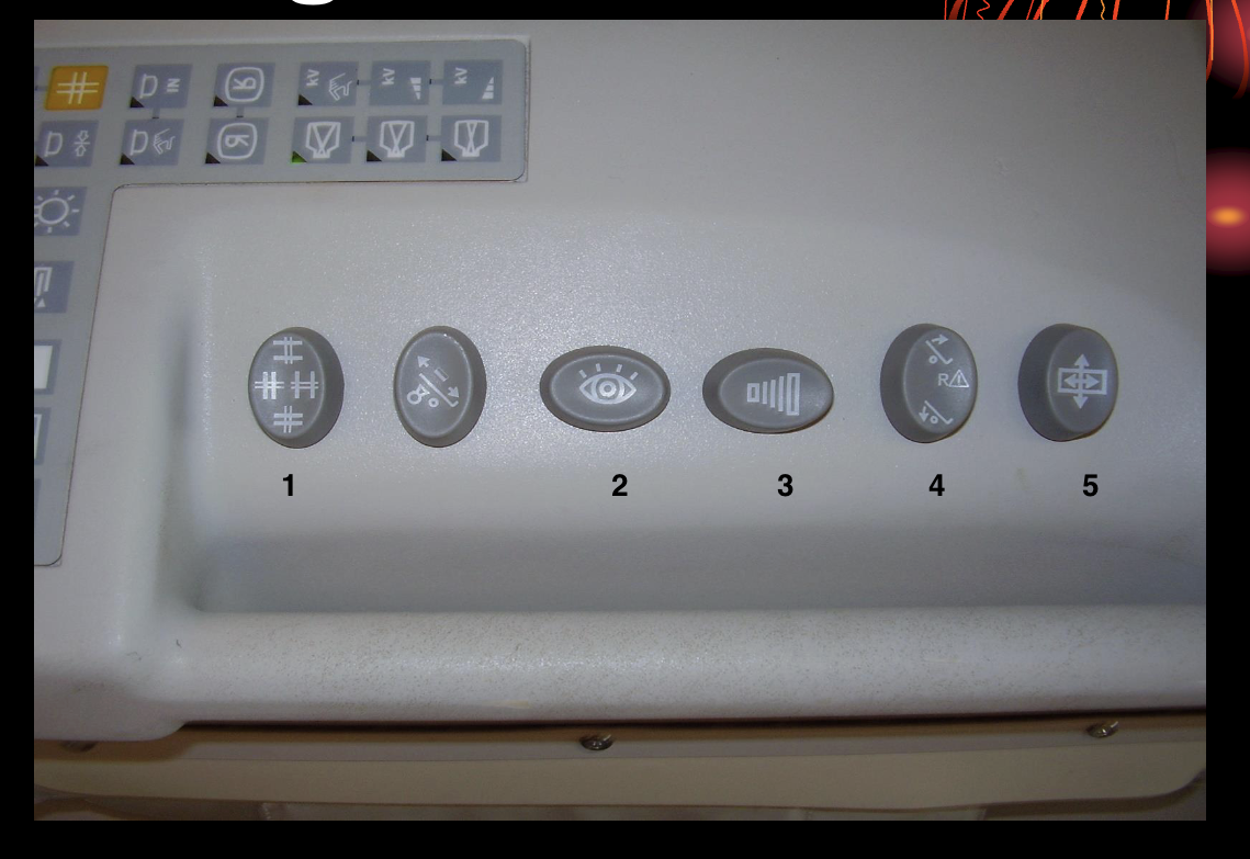
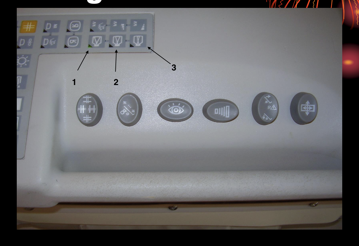
Collimation
Capture an image
Fluoro
Tilting table
Moving table
If the diameter is reduced to magify the image- how does that impact flux, minification and ultimately brightness? Patient exposure?
Flux → down
Minification → down
Brightness → down
Patient exposure → up
ABC/ABS/AGC/AERC → increases the mAs
Facts about digital fluoro
• Image acquisition is faster
• Can post process
• Similar equipment to a conventional fluoro room except
• two monitors
• Operates in radiographic mode (400 mA station = better for patient dose)
the x-ray beam is pulsed progressive fluoroscopy
PULSED PROGRESSIVE FLUOROSCOPY
Generator can be switched on and off rapidly = make it not too hot
Interrogation time
Tube switched on and meets selected levels of kVp and mA
Extinction time
Time required for the tube to be switched off
Duty Cycle - time tube is energized
Each must have times of less than one 1 ms.
FPIR - Flat panel Image receptor
Radiographic mode = regular MA
Replacing CCD’s
Made of cesium Iodide pixel detectors
Lighter, smaller than image intensifiers
Improvement to image as the spatial resolution is uniform and distortion free
High DQE
Improved contrast
Rectangular image
Greater density formula
mAs x KVP2 / SID2 x grid conversion factor
Grid conversion factors
16:1 → 6
12:1 → 5
10:1 → 5
8:1 → 4
6:1 → 3
5:1 → 2
no grid → 1
Advantages of CCDs for medical imagining
High spatial resolution
High SNR
High DQE
No warm up required
No spatial distortion
No maintence
Unlimited life
Unaffected by magnetic fields
Linear response
Lower patient radiation dose
Advantages of Flat planel IR
Distorion free images
Constant image quality
Improved contrast resolution over the entire image
High DQE
Rectangular image
Unaffected by external magnetic fields